Transcript
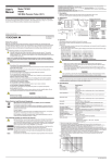
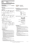
User's
Manual
1.Overview
701935
Deskew Correction Signal Source
The 701935 is a signal source used to correct the difference in the signal transfer time (skew, delay)
between voltage and current probes. If using a Yokogawa oscilloscope equipped with the Auto
Deskew function, the skew can be adjusted automatically.
Note
• When correcting the skew, use the falling edge of the waveform of the voltage and current
signals that the 701935 outputs.
• When connecting the current probe, match the direction of the arrows indicating the current
direction of the 701935 and the current probe.
• Securely connect the ground terminal (negative input on a differential probe, usually black) of
the probe to the
terminal of the voltage output terminal of the 701935).
• Accurate correction may not be possible near objects generating strong magnetic fields such
as a circuit with large current flowing or a transformer or near object generating strong electric
fields such as a radio.
Thank you for purchasing the Deskew Correction Signal Source (Model 701935).
To use the full capabilities of the 701935, please read this manual thoroughly before beginning
operation and use the 701935 correctly.
For inquiries, please see PIM112-01E (attached).
2.External Dimensions and Names of Parts
Name plate panel
(Unit: mm)
Rear View
69.2
To the power
connector of
the 701935
3rd Edition : December 2008 (YK)
All Rights Reserved, Copyright © 2003, Yokogawa Electric Corporation
Power connector
The following symbols are used on this instrument.
Warning: handle with care. Refer to the user’s manual or service manual. This symbol
appears on dangerous locations on the instrument which require special instructions for
proper handling or use. The same symbol appears in the corresponding place in the manual
to identify those instructions.
Functional ground terminal (do not use this terminal as a protective ground terminal.)
WARNING
Ground the Measurement Instrument
Be sure to employ protective earth ground on the measurement instrument.
Do Not Use in Locations of High Humidity
To prevent electric shock, do not use the 701935 in locations of high humidity.
Do Not Operate in an Explosive Atmosphere
To prevent injury and fire, do not use the 701935 in locations where explosion or fire is
possible in the presence of flammable liquids, vapors, and dust.
Output voltage
Output current
Output frequency
Fall time
Operating temperature range
Operation humidity range
Storage temperature range
Storage humidity range
Supply voltage
Approx. 15 kHz
Approx. 15 ns
5 to 40°C
20 to 80% RH (no condensation)
–20 to 60°C
20 to 80% RH (no condensation)
+12 V ± 1 V (using the B9825MJ power cable, supplied from the
probe power supply terminal provided by the DL Series Oscilloscope
or the power supply (Model 700938 or 701934))
150 mA or less
82.8 mm (W) × 32.5 mm (H) × 69.2 mm (D) (excluding protrusions)
Approx. 150 g
B9852MJ power cord 1 piece
User’s Manual
1 piece (this manual)
Complying standard •EN61326-1 Class A
•EN61326-2-1
•EN55011 Class A, Group 1
•C-tick EN55011 Class A, Group 1
This product is a Class A (for commercial environment) product.
Operation of this product in a residential area may cause radio
interference in which case the user is required to correct the
interference.
Complying standard EN61326-1 Table 2 (for use in industrial
locations)
Approx. 5 V
Emission
Immunity
Approx. –100 mA
4.Operating Procedure
1. Connect the power cord to the 701935 power connector.
2. Connect the other end of the power cord to the probe power supply of the DL Series
Oscilloscope or the 700938 or 701934 Power Supply.
3. Connect the tip of the voltage probe (passive probe or differential probe) to the voltage output
terminal of the 701935.
4. Connect the BNC connector end of the voltage probe (passive probe or differential probe) to the
signal input terminal of the DL Series Oscilloscope.
5. Connect (Clamp) the current probe to the current output terminal of the 701935.
6. Connect the BNC connector end of the current probe to the signal input terminal of the DL Series
Oscilloscope. Set the probe of the signal input terminal of the oscilloscope to the current probe
setting (setting in which current-to-voltage conversion is possible).
To the
When using a passive probe
in place of the differential
Operating environment limitations
CAUTION
This product is a Class A (for industrial environments) product. Operation of this product in
a residential area may cause radio interference in which case the user will be required to
correct the interference.
To the signal
input terminal of
the oscilloscope
terminal
To the probe power supply terminal*
To the 5-V
terminal
5-V terminal
terminal
To the signal input
terminal of the
oscilloscope
See below for operating environment limitations.
To the probe power supply
terminal or power supply
(Model 700938 or 701934)
Output voltage/current
(rectangular wave)
Supply current
External dimensions
Weight
Standard accessories
CAUTION
Do Not Damage the Current Output Terminal
Do not damage the insulation cover of the current output terminal of the 701935.
Do Not Short or Apply Voltage to the Output Terminal
Do not short or apply external voltage to the output terminal. Doing so can cause damage to
the 701935.
Use the Correct Power Supply for the 701935
Use the probe power supply terminal provided by the YOKOGAWA DL Series Digital
Oscilloscope (DL Series Oscilloscope) or the YOKOGAWA power supply (Model 700938 or
701934).
Use the Correct Power Cord
Use the power cord provided with the 701935 (Part No. B9852MJ).
Ground the 701935
The electric potential of the
terminal of the voltage output terminal is the same as that of
the grounding terminal of the DL Series Oscilloscope to which it is connected.
When Wiping off Dirt
To wipe off dirt, use a dry, soft, clean cloth. Do not use volatile chemicals such as benzene
or thinner for cleaning.
Other Handling Precautions
• Do not apply shock to the 701935 such as by dropping it or hitting it against another
object.
• Do not use the 701935 with the name plate panel facing down.
• Since the 701935 is compact and light, it is easy to tilt the 701935 when voltage and
current probes are connected (attached). Place the 701935 and probes on a flat even
surface and be sure that the 701935 does not tilt.
Current output terminal
(The
printed on the name plate
panel is for matching the direction
with the current probe arrow.)
3.Specifications
Make sure to comply with the following safety precautions in order to prevent accidents
such as an electric shock which impose serious health risks to the user and damage to the
instrument.
Power cord
B9852MJ
(Cord len.: 1.5 m)
2
The following safety precautions must be observed during all phases of operation.
Yokogawa Electric Corporation assumes no liability for the customer’s failure to comply with these
requirements. Read the user’s manual of the measurement instrument and have a thorough
understanding of the specifications and handling of the instrument before using the 701935.
82.8
32.5
Safety Precautions
Voltage
output terminal
terminal
5-V terminal
17.7
IM 701935-01E
3rd Edition
Differential Probe
701921
Black (to )
Red (to 5-V)
To the ground terminal
Waste Electrical and Electronic Equipment
To the probe power supply terminal*
Waste Electrical and Electronic Equipment (WEEE), Directive 2002/96/EC
(This directive is only valid in the EU.)
This product complies with the WEEE Directive (2002/96/EC) marking requirement.
This marking indicates that you must not discard this electrical/electronic product in
domestic household waste.
Product Category
With reference to the equipment types in the WEEE directive Annex 1, this product is
classified as a “Monitoring and Control instrumentation” product.
Do not dispose in domestic household waste. When disposing products in the EU,
contact your local Yokogawa Europe B. V. office.
To the signal input terminal
of the oscilloscope
To the probe power supply terminal*
Match the direction of the
arrows indicating the current
direction of the 701935 and
the current probe.
* If the oscilloscope is equipped with a probe
power supply, connect to that terminal. Be sure
not to exceed the probe power supply range.
current signals that the 701935 outputs. For the setup procedure of the oscilloscope, see the
manual that came with the oscilloscope.
8. Using the deskew function of the DL Series Oscilloscope, correct the signals so that the starting
sections of the falling edges of the waveforms match.
Example of Skew Correction When the Waveform Acquisition Mode Is Set to Averaging on
the DL Series Oscilloscope
Improper handling or use can lead to injury to the user or damage to the instrument.
This symbol appears on the instrument to indicate that the user must refer to the
user’s manual for special instructions. The same symbol appears in the corresponding
place in the user’s manual to identify those instructions. In the manual, the symbol is
used in conjunction with the word “WARNING” or “CAUTION.”
Before skew correction
WARNING Calls attention to actions or conditions that could cause serious or fatal injury to the
user, and precautions that can be taken to prevent such occurrences.
701935
(Deskew Correction
Signal Source)
7. On the DL Series Oscilloscope, observe the falling edges of the waveforms of voltage and
The Following Symbols are Used in this Manual.
Current probe
(701932, 701933,
701928, or 701989)
Power cord
B9852MJ
Voltage
signal
Current
signal
After skew correction
Starting section
of the falling edge
CAUTION Calls attentions to actions or conditions that could cause light injury to the user or
damage to the instrument or the user’s data, and precautions that can be taken to
prevent such occurrences.
Note
Calls attention to information that is important for proper operation of the instrument.
IM 701935-01E