1
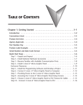
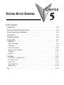
SYSTEM SETUP SCREENS
CHAPTER
5
In This Chapter...
Introduction . . . . . . . . . . . . . . . . . . . . . . . . . . . . . . . . . . . . . . . . . . . . . . . . . . . . . . .5–2
Accessing the System Setup Screens . . . . . . . . . . . . . . . . . . . . . . . . . . . . . . . . . . . .5–3
System Setup Screens Flowchart . . . . . . . . . . . . . . . . . . . . . . . . . . . . . . . . . . . . . . .5–4
Setup Menu . . . . . . . . . . . . . . . . . . . . . . . . . . . . . . . . . . . . . . . . . . . . . . . . . . . . . . . .5–5
Information Menu . . . . . . . . . . . . . . . . . . . . . . . . . . . . . . . . . . . . . . . . . . . . . . . . . . .5–6
Setting Menu . . . . . . . . . . . . . . . . . . . . . . . . . . . . . . . . . . . . . . . . . . . . . . . . . . . . . .5–7
Brightness . . . . . . . . . . . . . . . . . . . . . . . . . . . . . . . . . . . . . . . . . . . . . . . . . . . . . . . .5–7
Touch/Key Beep . . . . . . . . . . . . . . . . . . . . . . . . . . . . . . . . . . . . . . . . . . . . . . . . . . . .5–8
Calibration . . . . . . . . . . . . . . . . . . . . . . . . . . . . . . . . . . . . . . . . . . . . . . . . . . . . . . . .5–9
Clear User Memory . . . . . . . . . . . . . . . . . . . . . . . . . . . . . . . . . . . . . . . . . . . . . . . .5–10
Reset to Factory Default . . . . . . . . . . . . . . . . . . . . . . . . . . . . . . . . . . . . . . . . . . . . .5–10
Hourglass . . . . . . . . . . . . . . . . . . . . . . . . . . . . . . . . . . . . . . . . . . . . . . . . . . . . . . . .5–11
Rotation . . . . . . . . . . . . . . . . . . . . . . . . . . . . . . . . . . . . . . . . . . . . . . . . . . . . . . . . .5–12
Test Menu . . . . . . . . . . . . . . . . . . . . . . . . . . . . . . . . . . . . . . . . . . . . . . . . . . . . . . . .5–13
Serial Port2 - Loop Back Test . . . . . . . . . . . . . . . . . . . . . . . . . . . . . . . . . . . . . . . . .5–14
PLC Enquiry Test . . . . . . . . . . . . . . . . . . . . . . . . . . . . . . . . . . . . . . . . . . . . . . . . . .5–15
Buzzer Test . . . . . . . . . . . . . . . . . . . . . . . . . . . . . . . . . . . . . . . . . . . . . . . . . . . . . .5–15
Touch Panel Test . . . . . . . . . . . . . . . . . . . . . . . . . . . . . . . . . . . . . . . . . . . . . . . . . .5–16
Display Test . . . . . . . . . . . . . . . . . . . . . . . . . . . . . . . . . . . . . . . . . . . . . . . . . . . . . .5–16
Exit . . . . . . . . . . . . . . . . . . . . . . . . . . . . . . . . . . . . . . . . . . . . . . . . . . . . . . . . . . . . . .5–17
Chapter 5: System Setup Screens
1
2
3
4
5
6
7
8
9
10
11
12
13
14
A
B
C
D
Introduction
5–2
The C-more® Micro-Graphic panels include a series of built-in System Setup Screens that
allow the user to view detailed information about the panel, adjust features, test various
functions of the panel, clear memory, and reset all values and conditions back to the original
factory defaults.
The following is presented to give the user a detailed step by step look at:
• How to access the System Setup Screens
• What adjustments and features are available
• When and why the feature may need to be adjusted or used
• How to adjust and/or interrupt the features
The System Setup Screens are split into three categories to make it easy for the user to view
information, make adjustments, or test the panel. The three Setup Menu selections are:
Information
Here you will find the panel model number, detailed information about the panel’s available
memory and usage, the protocol being used by the panel, if an optional keypad bezel is installed
and version information for the firmware and boot loader.
Setting
This is the area for adjusting the brightness of the display, enabling or disabling the internal
beeper, calibrating the touch panel, clearing the user memory, resetting all of the settings back
to the factory defaults, and setting the loading screen hourglass icon delay time or disabling the
display of the hourglass icon.
The Setting factory default values are:
• Brightness value of 10
• The internal audible beeper enabled
• Forced touch panel calibration
• User program cleared from memory
• Hourglass icon delay of 350 ms.
• Horizontal display area orientation
Test Menu
The test menu includes options to initiate communication tests of the serial port, to test
communications with the PLC, to test operation of the panel’s beeper and to test the touch
panel surface. Refer to the serial port loop back test section of this chapter for details on loop
back connector wiring.
®
EA1-TCL-M Hardware User Manual, 2nd Ed. Rev. A, 07/13
Chapter 5: System Setup Screens
Accessing the System Setup Screens
To access the Setup Menu of the panel System Setup Screens, press the panel’s BAK [F1] and
ENT [F5] function keys simultaneously for three (3) seconds as shown below. The System
Setup Screens’ Setup Menu will be displayed as shown at the bottom of this page.
Press both the F1 and F5 function
keys simultaneously for 3
seconds to bring up the System
Setup Screens’ Setup Menu.
BAK
SETUP MENU
BAK
SETUP MENU
1. Information
2. Setting
3. Test Menu
4. Exit
SETUP MENU
1. Information
2. Setting
3. Test Menu
4. Exit
>
>
>
>
>
>
>
>
DWN
UP
DWN
ENT
ENT
EA1-T6CL
Landscape Mode
ENT
EA1-T6CL
Portrait Mode
®
>
>
>
ENT
ENT
UP
SETUP MENU
1. Information
2. Setting
3. Test Menu
4. Exit
>
>
>
UP
DWN
ENT
BAK
1. Information
2. Setting
3. Test Menu
4. Exit
BAK
UP
DWN
ENT
ENT
EA1-T4CL
Portrait
Mode
EA1-TCL-M Hardware User Manual, 2nd Ed. Rev. A, 07/13
EA1-T4CL
Landscape
Mode
1
2
3
4
5
6
7
8
9
10
11
12
13
14
A
B
C
D
5–3
Chapter 5: System Setup Screens
1
2
3
4
5
6
7
8
9
10
11
12
13
14
A
B
C
D
System Setup Screens Flowchart
5–4
Setup Menu
[pg. 5-5]
1. Information
[pg. 5-6]
1. Memory
[pg. 5-6]
2. Protocol
[pg. 5-6]
3. Extensions
[pg. 5-6]
4. Versions
[pg. 5-6]
2. Setting
[pg. 5-7]
1. Brightness
[pg. 5-7]
2. Touch / Key Beep
[pg. 5-8]
4. Calibration
[pg. 5-9]
5. Clear User Memory
[pg. 5-10]
6. Reset to Factory Default
[pg. 5-10]
7. Hourglass
[pg. 5-11]
8. Rotation
[pg. 5-12]
3. Test Menu
[pg. 5-13]
1. Serial Port – Loop Back Test
[pg. 5-14]
2. PLC Enquiry Test
[pg. 5-15]
3. Buzzer Test
[pg. 5-15]
4. Touch Panel Test
[pg. 5-16]
5. Display Test
[pg. 5-16]
4. Exit
[pg. 5-17]
®
Do you want to exit from System Screen?
No[F1] / Yes[F5]
EA1-TCL-M Hardware User Manual, 2nd Ed. Rev. A, 07/13
Chapter 5: System Setup Screens
Setup Menu
BAK
SETUP MENU
1. Information
2. Setting
3. Test Menu
4. Exit
>
>
>
>
To navigate the different selections under the Setup Menu,
use the function keys BAK [F1] to return to the project
screen or previous screen, UP [F3] to cursor up, DWN [F4]
to cursor down, and ENT [F5] to enter a selection.
UP
DWN
ENT
ENT
Pressing ENT [F5] with Information highlighted will take
you to the Information menu screen. See page 5-6.
BAK
SETUP MENU
1. Information
2. Setting
3. Test Menu
4. Exit
>
>
>
>
NXT
UP
Pressing ENT [F5] with Setting highlighted will take you to
the Setting menu screen. See page 5-7.
DWN
ENT
ENT
BAK
SETUP MENU
1. Information
2. Setting
3. Test Menu
4. Exit
>
>
>
>
NXT
UP
Pressing ENT [F5] with Test Menu highlighted will take you
to the Test Menu screen. See page 5-15.
DWN
ENT
ENT
BAK
SETUP MENU
1. Information
2. Setting
3. Test Menu
4. Exit
>
>
>
>
NXT
UP
DWN
ENT
®
Pressing ENT [F5] with Exit highlighted will allow the used
to decided whether to Exit or not Exit the System Setup
Screens. See page 5-18.
ENT
EA1-TCL-M Hardware User Manual, 2nd Ed. Rev. A, 07/13
1
2
3
4
5
6
7
8
9
10
11
12
13
14
A
B
C
D
5–5
Chapter 5: System Setup Screens
1
2
3
4
5
6
7
8
9
10
11
12
13
14
A
B
C
D
Information Menu
5–6
BAK
INFORMATION
1. Memory
2. Protocol
3. Extensions
4. Versions
NXT
>
>
>
>
UP
DWN
ENT
ENT
BAK
INFORMATION
1. Memory
2. Protocol
3. Extensions
4. Versions
NXT
>
>
>
>
UP
DWN
ENT
ENT
BAK
INFORMATION
1. Memory
2. Protocol
3. Extensions
4. Versions
NXT
>
>
>
>
UP
DWN
ENT
ENT
BAK
INFORMATION
1. Memory
2. Protocol
3. Extensions
4. Versions
NXT
>
>
>
>
UP
DWN
ENT
Pressing ENT [F5] with
Memory highlighted
will show the total
memory available,
memory usage and free
memory available for
the project.
Pressing ENT [F5] with
Protocol highlighted
will show the PLC
Protocol that has been
assigned to the panel
and the protocol
version.
Pressing ENT [F5] with
Extensions highlighted
will show if an optional
keypad bezel is installed
on the panel. The
example here shows the
EA-MG6-BZ2.
Pressing ENT [F5] with
Versions highlighted will
show the panel model,
firmware and boot loader
versions.*
BAK
MEMORY
Total:
3276800 Bytes
Usage:
0 Bytes
Free:
3276800 Bytes
BAK
PROTOCOL
Protocol Type :
K-Sequence
Version :
2.1.0.2
BAK
EXTENSIONS
Detected Devices :
BZ2
BAK
VERSIONS
Model:
Firmware :
Boot Loader :
EA1-T6CL
3.00.0.0
–––––
ENT
NOTE: Software and Firmware Version 3.0 or later is required with model EA1-T4CL. Version 2.5 or later is
required with model EA1-T6CL. Available for free download at www.automationdirect.com.
®
EA1-TCL-M Hardware User Manual, 2nd Ed. Rev. A, 07/13
Chapter 5: System Setup Screens
Setting Menu
BAK
SETTING
1. Brightness
>
2. Touch/Key Beep >
3. Calibration
>
4. Clear User Memory
5. Reset to Factory Def
6. Hourglass
>
7. Rotation
>
ENT
NXT
UP
DWN
ENT
Use the UP [F3] and DWN [F4] function keys to scroll
through the list of settings. The BAK [F1] function key will
return you to the previous screen. Use the ENT [F5]
function key to make your selection once you have the
setting highlighted.
The Setting screen includes the following:
Brightness - page 5-7
Touch/Key Beep – page 5-8
Calibration – page 5-9
Clear User Memory – page 5-10
Reset to Factory Default – page 5-10
Hourglass – page 5-11
Rotation – page 5-12
Setting – Brightness
BAK
SETTING
1. Brightness
>
2. Touch/Key Beep >
3. Calibration
>
4. Clear User Memory
5. Reset to Factory Def
6. Hourglass
>
7. Rotation
>
ENT
NXT
UP
DWN
ENT
With Brightness
highlighted, press
ENT [F5] to bring
up the screen
showing the current
value. The default is
10. The contrast can
be adjusted between
1 and 16, with 1
being the least
contrast and 16
being the greatest.
BAK
Brightness
Current Value :
10
UP
DWN
ENT
APL
NOTE: When the panel is powered through Port1 from a connected PC, the screen brightness is diminished
because the panel is running in Low-Power Mode. Connect an external 12-24 VDC power source when the
panel is installed in its application for full brightness.
®
EA1-TCL-M Hardware User Manual, 2nd Ed. Rev. A, 07/13
1
2
3
4
5
6
7
8
9
10
11
12
13
14
A
B
C
D
5–7
Chapter 5: System Setup Screens
1
2
3
4
5
6
7
8
9
10
11
12
13
14
A
B
C
D
Setting – Touch/Key Beep
5–8
BAK
SETTING
1. Brightness
>
2. Touch/Key Beep >
3. Calibration
>
4. Clear User Memory
5. Reset to Factory Def
6. Hourglass
>
7. Rotation
>
ENT
NXT
UP
DWN
ENT
With Touch/Key
Beep highlighted,
press ENT [F5] to
show the current
value for the internal
beeper. The default
is ON. The UP [F3]
and DWN [F4]
function keys can be
used to toggle
between the ON
and OFF state for
the beeper (enable
or disable). Use the
APL [F5] function
key to apply the
selection.
BAK
TOUCH KEY / BEEP
Current Value:
Enable
UP
DWN
ENT
APL
NOTE: Loading a project to the panel will override whatever selection is chosen for the beeper from the
System Setup Screens’ Beep on/off selection screen. The Beep on/off choice can be changed through the
System Setup Screens after a project is loaded.
®
EA1-TCL-M Hardware User Manual, 2nd Ed. Rev. A, 07/13
Chapter 5: System Setup Screens
Setting – Calibration
BAK
SETTING
1. Brightness
>
2. Touch/Key Beep >
3. Calibration
>
4. Clear User Memory
5. Reset to Factory Def
6. Hourglass
>
7. Rotation
>
ENT
NXT
UP
DWN
ENT
With Calibration
highlighted, press
ENT [F5] to bring
up the first
calibration screen as
shown on the right.
Touch the “cross” in
the upper left corner
as accurately as you
can. When the
screen is touched,
the cross will move
to each corner and
finally to the center
of the screen. If the
touch points are
within the built-in
calibration
tolerance, the final
screen will allow
you to either save
and quit from the
calibration
procedure, or allow
you to retry. If the
points that were
touched are not
within the
calibration
tolerance, you will
be returned to the
first calibration
screen and will need
to start over.
Press Cross Mark
Panel will not
Communicate
in this mode.
Press F1 to Quit
Press Cross Mark
Panel will not
Communicate
in this mode.
Press F1 to Quit
Press Cross Mark
Press F1 to Quit
F5 to Save & Quit
F1 to Retry
®
EA1-TCL-M Hardware User Manual, 2nd Ed. Rev. A, 07/13
1
2
3
4
5
6
7
8
9
10
11
12
13
14
A
B
C
D
5–9
Chapter 5: System Setup Screens
Setting – Clear User Memory
With Clear User
1
Memory
highlighted, press
2
ENT [F5]. You will
be given the choice
3
to either proceed
with clearing the
user memory by
4
pressing [F5] for
YES or allowed to
5
cancel by pressing
[F1] for NO.
6
7
8
9
Default
10 Setting – Reset to FactoryWith
Reset to
Factory Default
11
highlighted, press
ENT [F5]. Press [F5]
to restore all settings
12
to factory defaults
and clear user
13
memory. Press [F1] to
cancel.
14
Factory default values can also be reset by pressing F2 and F4 while cycling power to the panel.
The Factory Default values are:
A
• Brightness value of 10
• The internal audible beeper enabled
• Forced touch panel calibration
B
• User program cleared from memory
• Hourglass icon delay of 350 ms.
C
• Horizontal orientation
NOTE: User memory is cleared when factory defaults are reset. Use the C-more Micro-Graphic
D
programming software to read the program from the panel iand save a backup copy.
BAK
SETTING
NO
SETTING
1. Brightness
>
2. Touch/Key Beep >
3. Calibration
>
4. Clear User Memory
5. Reset to Factory Def
6. Hourglass
>
7. Rotation
>
ENT
NXT
UP
DWN
1. Brightness
>
2.Are
Touch/Key
Beepyou
>
you sure
4.want
Calibration
>
to clear
5.memory?
Clear User Memory
6. Reset to Factory Def
7.No[F1]
Hourglass/ Yes[F5]
>
8. Rotation
>
ENT
ENT
YES
DWN
NO
BAK
SETTING
SETTING
1. Brightness
>
2. Touch/Key Beep >
3. Calibration
>
4. Clear User Memory
5. Reset to Factory Def
6. Hourglass
>
7. Rotation
>
ENT
NXT
UP
DWN
ENT
1. Brightness
>
2.Are
Touch/Key
Beepyou
>
you sure
4.want
Calibration
>
to clear
5.memory?
Clear User Memory
6. Reset to Factory Def
7.No[F1]
Hourglass/ Yes[F5]
>
8. Rotation
>
ENT
YES
DWN
5–10
®
EA1-TCL-M Hardware User Manual, 2nd Ed. Rev. A, 07/13
Chapter 5: System Setup Screens
Setting – Hourglass
BAK
SETTING
1. Brightness
>
2. Touch/Key Beep >
3. Calibration
>
4. Clear User Memory
5. Reset to Factory Def
6. Hourglass
>
7. Rotation
>
ENT
®
NXT
UP
DWN
ENT
The Hourglass
selection listed under
the Setting menu can
be used to either
disable the display of
the hourglass icon or
set the amount of
delay time (0 ms to
1000 ms) desired
before it is displayed.
With Hourglass
highlighted, press
ENT [F5]. The UP
[F3] and DWN [F4]
function keys scroll
through the
selections. Use the
APL [F5] function
key to apply the
selection.
Explanation: An
hourglass icon is
displayed on the
panel anytime a new
screen is being
loaded until
communication is
established with the
new screen. If
communication is
established before the
delay has timed out,
no hourglass will be
displayed. The
hourglass icon can
also be disabled from
being displayed.
BAK
HOURGLASS
Delay/Disable ICON:
350ms
UP
DWN
ENT
APL
BAK
HOURGLASS
Delay/Disable ICON:
Disable
UP
DWN
ENT
APL
Hourglass Icon
EA1-TCL-M Hardware User Manual, 2nd Ed. Rev. A, 07/13
1
2
3
4
5
6
7
8
9
10
11
12
13
14
A
B
C
D
5–11
Chapter 5: System Setup Screens
1
2
3
4
5
6
7
8
9
10
11
12
13
14
A
B
C
D
Setting – Rotation
5–12
BAK
SETTING
NXT
1. Brightness
>
2. Touch/Key Beep >
3. Calibration
>
4. Clear User Memory
5. Reset to Factory Def
6. Hourglass
>
7. Rotation
>
UP
DWN
ENT
ENT
With Rotation
highlighted, press
ENT [F5] to show
the current
orientation. Press UP
[F3] and DWN [F4]
to toggle between the
portrait (vertical) and
landscape
(horizontal)
orientation. Use the
APL [F5] function
button to apply the
selection.
BAK
ROTATION
Portrait Mode:
off
UP
DWN
ENT
APL
Note: Loading a project to the panel will override the orientation choosen from the System Setup Screens’
Rotation selection screen. The selected orientation is displayed only when in the System Setup Screens.
®
EA1-TCL-M Hardware User Manual, 2nd Ed. Rev. A, 07/13
Chapter 5: System Setup Screens
Test Menu
BAK
TEST MENU
1. Serial Port - Loop Back
2. PLC Enquiry Test
3. Buzzer Test
4. Touch Panel Test
5. Display Test
UP
DWN
ENT
ENT
®
Use the UP [F3] and DWN [F4] function keys to scroll
through the list of tests. The BAK [F1] function key will
return you to the previous screen. Use the ENT [F5] function
key to make your selection once you have the test
highlighted.
Serial Port - Loop Back Test – page 5-14
PLC Enquiry Test – page 5-15
Buzzer Test – page 5-15
Touch Panel Test – page 5-16
EA1-TCL-M Hardware User Manual, 2nd Ed. Rev. A, 07/13
1
2
3
4
5
6
7
8
9
10
11
12
13
14
A
B
C
D
5–13
Chapter 5: System Setup Screens
Test Menu – Serial Port - Loop Back Test
BAK
TEST MENU
1. Serial Port - Loop Back
2. PLC Enquiry Test
3. Buzzer Test
4. Touch Panel Test
5. Display Test
UP
DWN
ENT
ENT
5
RS-232 Loop-back Connector
User Constructed
15-pin D-sub
(male)
2 TXD
15
3
RXD
7
CTS
8
RTS
1
Wiring Diagram
RS-422/485 Loop-back Connector
User Constructed
7 CTS 15-pin D-sub
(male)
8 RTS
9
RXD+
11
TXD+
10
RXD–
12
TXD–
15
With Serial Port Loop Back Test
highlighted, press
ENT [F5] to bring up
the screen shown to
the right. At this
point, either connect
the RS-232 loop back
connector or the
RS-422/485 loop
backconnector,
depending on which
type of
communications
connection is being
used, and press ENT
[F5] to start the test.
If the test is passing,
the Receive Counts
will equal the Bytes
Sent. If the serial port
is not working, then
the Error Counts will
equal the Bytes Sent.
The RTS/CTS signals
will also show either
pass or fail as shown
to the right. The test
will continue until
the BAK [F1] key is
pressed.
BAK
TEST MENU
1. Serial Port - Loop Back
2. PLC Enquiry Test
Use Loop-Back
3. Buzzer Test
Connector and
4. Touch Panel Test
Press ENT
5. Display Test
DWN
ENT
ENT
BAK
LOOP BACK TEST
Serial Port :
Bytes Sent
Rcv. Counts
Err. Counts
RTS/CTS
124
124
0
pass
DWN
ENT
BAK
LOOP BACK TEST
Serial Port :
Bytes Sent
Rcv. Counts
Err. Counts
RTS/CTS
124
0
124
fail
UP
DWN
ESC
1
®
UP
ESC
Wiring Diagram
5–14
UP
EA1-TCL-M Hardware User Manual, 2nd Ed. Rev. A, 07/13
ENT
Chapter 5: System Setup Screens
Test Menu – PLC Enquiry Test
BAK
TEST MENU
1. Serial Port - Loop Back
2. PLC Enquiry Test
3. Buzzer Test
4. Touch Panel Test
5. Display Test
UP
DWN
ENT
ENT
BAK
PLC ENQUIRY TEST
DirectLogic K-Sequence
Data1 : Test Passed
Data2 : Test Passed
Data3 : Test Passed
Data4 : Test Passed
ESC
With PLC Enquiry
Test highlighted,
press ENT [F5] to
bring up the screen
shown to the right.
If the PLC is
connected to the
panel, press ENT
[F5] to start the test.
Four data tests will
be performed and
indicated as either
Test Passed or Test
Failed as shown on
this page. The BAK
[F1] key can be
pressed to cancel the
test and/or returned
to the previous
screen.
BAK
TEST MENU
1. Serial Port - Loop Back
2. PLC Enquiry Test
Connect Panel to
3. Buzzer Test
PLC
4. Touch Panel Test
5. Display Test
UP
DWN
ENT
ENT
Test Menu – Buzzer Test
BAK
TEST MENU
1. Serial Port - Loop Back
2. PLC Enquiry Test
3. Buzzer Test
4. Touch Panel Test
5. Display Test
With Buzzer Test selection highlighted, press ENT [F5] to
run the test on the internal audible beeper. The beeper will
sequence up the scale through eight notes and then start over.
The BAK [F1] key can be pressed to cancel the test.
UP
DWN
ENT
ENT
NOTE: The beeper tone is not selectable. The beeper function can not be turned on or off from this screen,
refer to the Setting menu.
NOTE: When the panel is powered through Port1 from a connected PC, the screen brightness is diminished
because the panel is running in Low-Power Mode. Connect an external 12-24 VDC power source when the
panel is installed in its application for full brightness.
®
EA1-TCL-M Hardware User Manual, 2nd Ed. Rev. A, 07/13
1
2
3
4
5
6
7
8
9
10
11
12
13
14
A
B
C
D
5–15
Chapter 5: System Setup Screens
Test Menu - Touch Panel Test
With Touch Panel Test
1
highlighted, press ENT
[F5] to bring up the
2
screen shown to the
right. Touch any area of
3
the screen to visualize
the active area of the
touch screen. If the
4
touch panel area is
working properly, the
5
screen will blacken at
the area touched. Use
this test to identify any
6
area that is not
responding properly.
7
Press any key [F1 to F5]
to return to the Test
Menu.
8
9 Test Menu - Display TestWith Display Test
highlighted, press ENT
10
[F5] to bring up the
screen shown to the
right. After a few
11
seconds a scrolling RGB
color test will begin.
12
Use this test to identify
any area that is
13
displaying colors
incorrectly. Press any
key [F1 to F5] to return
14
to the Test Menu.
A
B
C
D
BAK
TEST MENU
1. Serial Port1 - Loop Back
2. PLC Enquiry Test
3. Buzzer Test
4. Touch Panel Test
5. Display Test
UP
Press Key to Quit
DWN
ENT
ENT
Press Key to Quit
BAK
TEST MENU
1. Serial Port1 - Loop Back
2. PLC Enquiry Test
3. Buzzer Test
4. Touch Panel Test
5. Display Test
UP
DWN
Red
Green
ENT
ENT
5–16
®
Press Key to Quit
EA1-TCL-M Hardware User Manual, 2nd Ed. Rev. A, 07/13
Blue
Chapter 5: System Setup Screens
Exit
BAK
SETUP MENU
1. Do
Information
you want to >
2. exit
Setting
>
from System
3. Screen?
Test Menu
>
4. Exit
>
No[F1] / Yes[F5]
UP
With Exit highlighted, press ENT [F5] to bring up the screen
shown to the left. You will be given the choice to either proceed
with exiting the System Setup Screens by pressing [F5] for YES
or allowed to cancel by pressing [F1] for NO. You will be
returned to the project screen if answering YES.
DWN
ENT
ENT
If there is no user program loaded into the panel, then a NO
USER PROGRAM message as shown to the left will be displayed.
BAK
SETUP MENU
1. Do
Information
you want to >
2. exit
Setting
>
from System
3. Screen?
Test
MenuPROGRAM
>
NO
USER
4. Exit
>
No[F1] / Yes[F5]
UP
DWN
ENT
ENT
®
EA1-TCL-M Hardware User Manual, 2nd Ed. Rev. A, 07/13
1
2
3
4
5
6
7
8
9
10
11
12
13
14
A
B
C
D
5–17