1
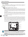
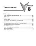
TROUBLESHOOTING
CHAPTER
8
In This Chapter...
C-more 6” Micro-Graphic Panel does not Power up . . . . . . . . . . . . . . . . . . . . . . . .8–2
Display is Blank . . . . . . . . . . . . . . . . . . . . . . . . . . . . . . . . . . . . . . . . . . . . . . . . . . . . .8–2
Display is Dim . . . . . . . . . . . . . . . . . . . . . . . . . . . . . . . . . . . . . . . . . . . . . . . . . . . . . .8–3
No User Program . . . . . . . . . . . . . . . . . . . . . . . . . . . . . . . . . . . . . . . . . . . . . . . . . . .8–3
Lost Firmware – Red ‘Update Mode’ Screen Displayed . . . . . . . . . . . . . . . . . . . . . .8–4
Updating Firmware . . . . . . . . . . . . . . . . . . . . . . . . . . . . . . . . . . . . . . . . . . . . . . . . . .8–4
No Communications between Panel and PC (Personal Computer) . . . . . . . . . . . .8–5
No Communications between Panel and PLC . . . . . . . . . . . . . . . . . . . . . . . . . . . . .8–7
Panel & PLC Error Codes . . . . . . . . . . . . . . . . . . . . . . . . . . . . . . . . . . . . . . . . . . . . .8–8
C-more Micro-Graphic Panel Runtime Errors . . . . . . . . . . . . . . . . . . . . . . . . . . . . . .8–9
Electrical Noise Problems . . . . . . . . . . . . . . . . . . . . . . . . . . . . . . . . . . . . . . . . . . . .8–10
Chapter 8: Troubleshooting
1
2
3
4
5
6
7
8
9
10
11
12
13
14
A
B
C
D
Troubleshooting
8–2
The following are some problems that may be encountered during the installation and
operation of your C-more® Micro-Graphic panel. We have made some suggestions on
what to check in order to correct the problem.
C-more 6” Micro-Graphic Panel does not Power up
Powered from 5 VDC: If the panel’s display is blank, not responding, and the panel is powered
from a 5 VDC power source such as a PC or PLC, check the incoming DC voltage level with
a voltmeter. The DC voltage level should be in the range of 4.75 to 5.25 VDC. If the incoming
DC voltage is zero, check any fusing that may be in the circuit. If the fuse is open, determine
cause and replace.
Powered from 12-24 VDC: If the panel’s display is blank, not responding, and the panel is
powered from a 12-24 VDC power source, check the incoming DC voltage level to the adapter
with a voltmeter. The DC voltage level to the adapter should be in the range of 10.2-26.4 VDC.
If the incoming DC voltage is zero, check any fusing that may be in the circuit. If the fuse is
open, determine cause and replace.
Display is Blank
Also if the panel’s display is blank, check the TxD and RxD indicators on the back side of the
panel while the panel is communicating with the PLC. The LED indicators should be on or
flashing at a fast rate. Indicator activity shows that the panel is communicating with the PLC.
If there is communication activity, but the display is still blank, there is the possibility the
program in the PLC is controlling the display. Try pressing the F1 and F5 keys simultaneously
for 3 seconds. The panel will change to the System Setup Screen menu if the screen is being
forced to display a blank screen by the PLC program. Also, check the PLC program, it may have
the screen in the off state by placing a 0 in the current screen tag.
TxD Indicator
Port1
RxD Indicator
Port1
TxD Indicator
Port2
R01. 1 2 3 4 5
MODEL:EA1-S6MLW
R
INPUT:12-24V 6.5W
Date code:****
MADE IN CHINA
LISTED
7M17
IND.CONT.EQ.
EA1-S6MLW + serial number
8
1
15
9
RxD Indicator
Port2
NOTE: When the panel is powered through Port1 from a connected PLC or PC, the screen brightness is
diminished because the panel is running in Low-Power Mode. For full brightness, connect an external
12-24 VDC power source to the panel’s power connection. Low-Power Mode is intended for initial
programming. For full brightness, connect an external 12-24 VDC power source when the panel is installed
in its application..
®
EA1-MG6-USER-M Hardware User Manual, 1st Ed. Rev E, 07/13
Chapter 8: Troubleshooting
Display is Dim
NOTE: When the panel is powered through Port1 from a connected PLC or PC, the screen brightness is
diminished because the panel is running in Low-Power Mode. For full brightness, connect an external
12-24 VDC power source to the panel’s power connection. Low-Power Mode is intended for initial
programming. For full brightness, connect an external 12-24 VDC power source when the panel is installed
in its application.
BAK
BAK
SETTING
LCD CONTRAST
1. LCD Contrast
>
2. Backlight
>
3. Beep
>
4. Calibration
>
5. Clear User Memory
6. Reset to Factory Default
NXT
Current Value :
8
UP
UP
DWN
DWN
ENT
ENT
APL
ENT
Press the F1 and F5 keys simultaneously for 3 seconds and the panel will bring up the the
System Setup Screen menu. Select the Setting menu, and then select item 1; LCD Contrast.
The default value is 8. Adjust the current value from 1 to 16 and the panel's contrast should
become greater as the value moves toward 16 and it should become less as the value moves
toward 1. If this does not happen, then the panel may need to be replaced. See note above.
LCD Contrast: The contrast of LCD has 16 levels of adjustment. The default is a value of 8.
No User Program
If the panel is displaying the message "No User Program" after it is powered up, then there is
no project downloaded into the panel. Using the EA-MG-PGMSW C-more Micro-Graphic
Programming Software, download your project to the panel.
BAK
SETUP MENU
1. Information
Do you want to >
2. Setting
>
exit from System
3. Test
MenuPROGRAM
>
Screen?
NO
USER
4. Exit
>
No[F1] / Yes[F5]
UP
DWN
ENT
ENT
®
EA1-MG6-USER-M Hardware User Manual, 1st Ed. Rev E, 07/13
1
2
3
4
5
6
7
8
9
10
11
12
13
14
A
B
C
D
8–3
Chapter 8: Troubleshooting
Lost Firmware – Red ‘Update Mode’ Screen Displayed
1
2
3
4
5
6
7
8
9
10
11
12
13
14
A
B
C
D
8–4
If the C-more Micro-Graphic panel’s firmware becomes corrupted or for some reason is lost
from the panel’s memory, the panel will display the Update Mode screen as shown below. This
can happen if communication between the PC and the panel is interupted during a firmware
update. To resolve the problem, try the following steps in the order shown:
1.) Cycle power to the panel.
2.) If the problem persists, update the firmware to the panel using the Update Firmware utility
under the Panel pull down menu in the EA-MG-PGMSW Programming Software.
3.) If the problem persists, depress function keys F1 and F5 while cycling power to the panel.
The panel should come up in the red Update Mode screen as shown below. Perform Step 2
again.
4.) If there is still a problem, call Tech Support @ 770-844-4200.
=Update Mode=
Port1 [ 6pin]
115.2K / 8 / 0 / 1
Port2 [ 15pin]
115.2K / 8 / 0 / 1
Data Change Push Key1
Updating Firmware
The panel firmware version must match both the programming software version and the version
that the program was saved as. If a version needs to be updated, for example, to take advantage
of new functionality or product line additions follow these steps:
1.) Create a backup copy of the project on the PC. From the C-more Micro-Graphic
programming software, read the project from the panel and save to a desired location.
2.) Update the programming software on the PC.
3.) Cycle power to the panel.
4.) Update the firmware to the panel using the Update Firmware utility under the Panel pull
down menu in the EA-MG-PGMSW Programming Software.
5.) Open the project in the updated programming software. Save the project. Transfer the
project to the panel.
®
EA1-MG6-USER-M Hardware User Manual, 1st Ed. Rev E, 07/13
Chapter 8: Troubleshooting
No Communications between Panel and PC (Personal Computer)
There are three possible causes that prevent transferring the project to the C-more MicroGraphic panel.
1. Panel not on setup screen (press F1 and F5) - Press and hold the F1 and F5 buttons
simultaneously for three seconds to enter the setup screen.
2. Cable not connected - Double check the programming cable asembly to make sure the panel is
correctly connected to the USB port on the PC.
PC to Panel Programming
Cable Assembly
(Includes serial & USB cables)
EA-MG-PGM-CBL
USB
Cable
Serial
Cable
USB to RS232
Converter
User PC
C-more 6 inch
Micro Graphic
Panel
NOTE: When properly installed the programming cable will look like a serial communications port to the PC.
No communications between panel and PC continued top of next page.
®
EA1-MG6-USER-M Hardware User Manual, 1st Ed. Rev E, 07/13
1
2
3
4
5
6
7
8
9
10
11
12
13
14
A
B
C
D
8–5
Chapter 8: Troubleshooting
No Communications between Panel and PC (Personal Computer) (cont’d)
1
2
3
4
5
6
7
8
9
10
11
12
13
14
A
B
C
D
8–6
3. Not using the correct COM port assigned to the USB adapter - If the C-more Micro-Graphic
panel is on the setup screen and the cable
connection is correct, then check the PC COM
port setting.
If you are unsure which COM port the C-more
Micro-Graphic programming cable is connected
to, click on the Device Manager button. This
will open Windows ® Device Manager.
In the Device Manager window, view the active
ports by clicking the + button beside the Ports
(COM & LPT) menu item. The C-more MicroGraphic panel uses a USB driver called Koyo
USB-Serial Comm Port.
COM4 is the USB port used in this example. If you
cannot find the Koyo USB-Serial Comm Port under
Ports (COM & LBT) in Device Manager, the USB
driver may not be correctly installed or the driver has
a problem. Disconnect the cable from the PC and
follow these steps to re-install the driver:
• Uninstall the C-more Micro-Graphic programming
software.
• Unplug the cable between the PC and the C-more
Micro-Graphic panel.
• Re-install the C-more Micro-Graphic programming
software. Make sure the install USB driver checkbox
is selected.
If you have selected the correct COM port and the
error still occurs, try connecting the programming
cable to a different USB port on the PC and try again.
If the problem persists, call Technical Support at
(770) 844-4200, available from 9:00 A.M. to 6:00
P.M. Eastern Time.
®
EA1-MG6-USER-M Hardware User Manual, 1st Ed. Rev E, 07/13
Chapter 8: Troubleshooting
No Communications between Panel and PLC
The C-more Micro-Graphic panel communicates with a designated PLC or controlling device
through the panel’s RS-232 RJ12 serial communications port (Port1) or RS-232 / RS-485 / RS422 communications port (Port2).
Check the Txd and Rxd status indicators of the port connected to the PLC. The indicator
LED’s should be on or flashing at a fast rate. If there is activity on the LED indicators, then the
panel and PLC are communicating.
TxD Indicator
Port1
RxD Indicator
Port1
TxD Indicator
Port2
R01. 1 2 3 4 5
MODEL:EA1-S6MLW
R
INPUT:12-24V 6.5W
Date code:****
MADE IN CHINA
LISTED
7M17
IND.CONT.EQ.
EA1-S6MLW + serial number
8
1
15
9
RxD Indicator
Port2
On either serial communications port, if there is no activity on one or both TxD and RxD LED
status indicators, then it should be suspected that either:
• The communication settings are incorrect - Open Panel Manager in the C-more Micro-Graphic
programming software and verify that the correct panel Comm. Port is selected. Verify that the
correct PLC protocol is selected and properly configured.
• The cable is bad and needs to be replaced - Try a proven cable.
• Test panel serial port. See Chapter 5, Serial Port - Loop Back Test. If the panel’s serial port is
defective and if a cable is available, switch to the other port on the panel. If possible switch the panel
with a panel that is communicating properly.
• The serial port on the PLC is defective
Electrical noise, pulse generating wiring and/or improper grounding can also cause problems
with communications. Refer to the Electrical Noise Problems section in this chapter for
additional help if electrical noise is suspected. Selecting a lower communication rate in Panel
Manager may help the panel resist noise.
®
EA1-MG6-USER-M Hardware User Manual, 1st Ed. Rev E, 07/13
1
2
3
4
5
6
7
8
9
10
11
12
13
14
A
B
C
D
8–7
Chapter 8: Troubleshooting
Panel & PLC Error Codes
1
2
3
4
5
6
7
8
9
10
11
12
13
14
A
B
C
D
8–8
The C-more Micro-Graphic panel includes built-in PLC communication protocol diagnostics
that monitor the exchange of data between the panel and the PLC. The diagnostics look for the
proper exchange of data, correct handshaking signals, addressing errors, incorrect data bytes,
wrong packet format, etc. The diagnostics also monitor and display any of the errors that the
designated PLC generates if there is a problem with the PLC’s communications. The PLC
generated errors are interpreted by the C-more Micro-Graphic programming software and are
displayed across the top of the panel’s display embedded as a hexadecimal value in error code
P499.
If a C-more Micro-Graphic communication error does occur, the error message will be displayed
in the upper left of the panel’s display screen along with the error code number. The error code
with error message will blink off and on. .
NOTE: See Appendix A: Panel & PLC Error Code Tables for a complete list of all error codes.
Panel Communications
Error Code Example
P001: PLC COM Time Out
Start
®
Stop
EA1-MG6-USER-M Hardware User Manual, 1st Ed. Rev E, 07/13
Chapter 8: Troubleshooting
C-more Micro-Graphic Panel Runtime Errors
The C-more Micro-Graphic panel includes built-in diagnostics that check for proper operation
of the panel when it is running a project that has been transferred to its memory. Faults detected
while the panel is running will produce a “Runtime” error. These errors are displayed in a
popup window in the center of the panel’s display.
Troubleshooting a Panel Runtime Error:
Follow these steps to troubleshoot a panel runtime error.
1. Check the panel cable connections.
2. Cycle power at the panel.
3. Resend the project.
4. If the error still occurs, reset the panel back to factory default. Refer to Chapter 5 for details
NOTE: User memory is cleared when factory defaults are reset. Use the C-more Micro-Graphic
programming software to read the program from the panel and save a backup copy.
Panel Errors
If more than one panel error occurs, each error message will display sequentially for three
seconds with a two second delay between each message.
When only one panel error is active, that message will display continuously until it is no longer
active.
Micro-Graphic Panel Errors
Error Code Error Message
Possible Solutions
R001
PC software tool Timeout
R002
CRC Error occurred during
project transfer from PC.
Check cables and connections.
Cycle power at the panel.
See Chapter 8 for Electrical Noise Problems.
Check the area for sources of noise: electrical motors, transformers, etc.
Check for proper grounding
Resend the project.
R003
R006
Project Check Sum Error.
Resend Project file to Panel.
Protocol Module Check Sum
Error. Resend Project File to
Panel
Panel Check Sum Error. Panel
Info (Not Project) will be
initialized.
SW Ver. Mismatch. Use
software Ver.xx.xx.
R100
Option module detected
without external power
R004
R005
R101
Cycle power.
Resend the project.
From the Setup Menu screen, reset panel options.
Update to current version programming software and panel firmware.
EA-MG-SP1 or EA-MG-P1 optional power adapter module is installed
on a C-more 3” Micro-Graphic panel without a 12-24 VDC power
source. Provide 12-24 VDC power to the optional module.
EA-MG-SP1 or EA-MG-P1 optional power adapter module for a C-more
Unsupported module detected 3” Micro-Graphic panel is installed on a C-more 6” Micro-Graphic panel.
Remove the EA-MG-SP1 or EA-MG-P1.
®
EA1-MG6-USER-M Hardware User Manual, 1st Ed. Rev E, 07/13
1
2
3
4
5
6
7
8
9
10
11
12
13
14
A
B
C
D
8–9
Chapter 8: Troubleshooting
Electrical Noise Problems
1
2
3
4
5
6
7
8
9
10
11
12
13
14
A
B
C
D
8–10
Most noise problems result from improper grounding of the system. A good earth ground can
be the single most effective way to correct noise problems. If a ground is not available, install a
ground rod as close to the system as possible. Ensure all ground wires are single point grounds
and are not daisy chained from one device to another. Ground metal enclosures around the
system. A loose wire can act as a large antenna, introducing noise into the system. Therefore,
tighten all connections in your system. Loose ground wires are more susceptible to noise than
the other wires in your system. Review Chapter 4: Installation & Wiring if you have questions
regarding how to ground the touch panel.
Electrical noise can enter the system through the power source for the touch panel. Installing a
properly wired isolation transformer (neutral grounded) for all AC sources can help the
problem, but only if wired correctly. DC sources should be well-grounded good quality
supplies.
Never run communication cables or low-voltage power wiring close to high voltage wiring or
pulse generating wiring that controls such devices as solenoids, servos, VFOs, etc.
Selecting a lower communication rate in Panel Manager may help the panel resist noise.
®
EA1-MG6-USER-M Hardware User Manual, 1st Ed. Rev E, 07/13