1
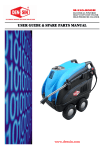
C-2070E Electric Powered Ultra High Pressure Water Blaster Machine www.densin.com Introductions Introductions Congratulations on your purchase of the DEN-SIN C-2070E UHP Water Blaster. DEN-SIN makes no warranty of any kind with regards to this material, including, but not limited to, the implied warranties of merchantability and fitness for a particular purpose. DEN-SIN expressly disclaims all responsibility and liability for the installation, use, purpose, maintenance, and support of third party products. This document or part of it may not be photocopied, or in any other way reproduced, or translated to other languages without the prior written consent of DEN-SIN. Warning Read this user manual before you start up your Water Blaster the first time. This machine is a Water Blaster producing water jet under high-pressure, which is why severe injuries can occur if the safety precautions are not observed. Therefore a full understanding of the contents of this instruction manual is required, in order to prevent injuries to you, objects and persons near by. Safety The following symbols are used in this manual to indicate procedures that if not followed, may results in personal injuries or damage to equipment. WARNING is used to alert the reader of procedures or WARNING practice which if not followed correctly could result in personal injuries. CAUTION is used to alert the reader of procedures or CAUTION practice which if not followed correctly could result in damage to machine or other equipment. NOTE is used to highlight important information that may NOTE assist the reader carrying out the procedure or understanding the text. Version 00 : 2014 C-2070E V-00 -2- Table Of Contents Table Of Contents Introductions ............................................................................................................. 1 Table Of Contents ....................................................................................................... 3 1. Getting Acquainted With Your UHP Water Blaster ................................................ 5 Fast And Efficient Cleaning ................................................................................................... 5 Specifications ......................................................................................................................... 5 ID-Plate ................................................................................................................................... 5 Applications ........................................................................................................................... 5 Unpacking .............................................................................................................................. 6 Hose/Tumblebox Connection .............................................................................................. 6 Hose / Pump Connection .................................................................................................... 10 Water Supply Connection ................................................................................................... 10 Control Panel ....................................................................................................................... 12 Operations............................................................................................................................ 12 Filter Maintenance And Filter Change ............................................................................... 14 2. Safety And Protection Information ...................................................................... 15 IMPORTANT MEDICAL INFORMATION............................................................................. 15 WARNING ................................................................................................................. 15 Safety Precautions ............................................................................................................... 16 General Safety & Application Guidelines ........................................................................... 17 Application Guidelines ........................................................................................................ 17 3. Maintenance and troubleshooting ....................................................................... 19 Maintenance Schedule ........................................................................................................ 19 Do`s & Don’t`s ...................................................................................................................... 19 Troubleshooting .................................................................................................................. 20 Pump Service & Repair Instructions .................................................................................. 21 Inspection And Replacement Of Floating Plunger Components ..................................... 25 Torque specifications: ......................................................................................................... 26 Tumble Box Service & Repair Instructions ( Dual Mode Functions ) ............................. 27 4. Available Accessories ........................................................................................... 30 5. Spare Parts List ..................................................................................................... 31 Main assembly ..................................................................................................................... 31 Main assembly spare-parts list .......................................................................................... 32 Water tank assembly........................................................................................................... 34 Water tank assembly spare-parts list ................................................................................ 35 Filter assembly (standard) ................................................................................................. 36 Filter Assembly Part list (Standard) .................................................................................. 36 Filter assembly (Optional) .................................................................................................. 37 Filter Assembly Partlist (Optional) .................................................................................... 37 Gauge assembly ................................................................................................................... 38 Gauge assembly spare-parts list ........................................................................................ 38 Pump coupling assembly .................................................................................................... 39 Pump coupling assembly spare-parts list ......................................................................... 40 Pump fluid-end assembly ................................................................................................... 41 Pump fluid-end assembly spare-parts list ........................................................................ 42 Pump power-end assembly part ........................................................................................ 43 Oil Seal assembly ................................................................................................................. 45 Oil Seal Assembly spare-parts list ...................................................................................... 45 Rotating gun / Hoses / Un-loader assem .......................................................................... 46 Rotating gun / Hoses / Un-loader assembly spare-parts list .......................................... 47 Pneumatic un-loader / dump type assembly spare-parts list ......................................... 49 Air Operated Rotating Gun Assembly (Dual Mode) .......................................................... 50 C-2070E V-00 -3- Table Of Contents Rotating gun spare-parts assembly ................................................................................... 50 Pneumatic Un-loader / Dump type assembly (Dual Mode) ............................................. 51 Pneumatic Un-loader / Dump type assembly spare-parts list (Dual Mode) .................. 52 Rotating gun spare-parts assembly ................................................................................... 53 Rotating gun spare-parts assembly spare-parts list ........................................................ 54 Front trigger for rotating gun assembly ............................................................................ 55 Front trigger for rotating gun assembly spare-parts list ................................................. 55 Swivel for rotating gun assembly ....................................................................................... 56 Swivel for rotating gun assembly spare-parts list ............................................................ 56 Trigger dump-gun & hose assembly .................................................................................. 57 Trigger dump-gun & hose assembly spare-parts list ....................................................... 57 Rotating Nozzle Assembly .................................................................................................. 59 Rotating Nozzle Assembly spare-parts list ....................................................................... 60 6. Wiring diagram..................................................................................................... 61 7. Declaration and Warranty ................................................................................... 62 EU declaration of conformity ............................................................................................. 62 Warranty .............................................................................................................................. 62 The information contained in this user guide is subject to change without notice. NOTE C-2070E V-00 -4- 1. Getting Acquainted With Your UHP Water Blaster 1. Getting Acquainted With Your UHP Water Blaster Fast And Efficient Cleaning The DEN-SIN UHP Water Blaster C-2070E enables you to get more cleaning done in less time. This DEN-SIN cold water UHP Water Blaster offers you high performance and a design optimized for heavy duty use. The design of the surrounding frame safeguard the vital parts during transport and use, and the high performance gives you the opportunity to solve an array of blasting tasks. The Water Blaster is designed for industrial and for offshore use. All pump parts fittings and pipes in contact with water are made of noncorrosive materials. Together with the carbide coated plungers, long life seals and stainless steel valves, it ensures long life and high durability. Specifications Model C-2070/26E 50Hz C-2070/26E 60Hz Motor Motor Speed Working Pressure Flow Capacity Power Supply Dimensions LxWxH Weight Hp kW rpm psi Bar gpm l/min Voltage mm kg 125 92 1450 30000 2070 6.8 26 415 V 50Hz 2380x1400x1850 1700 125 92 1750 30000 2070 6.8 26 440 V 60Hz 2380x1400x1850 1700 ID-Plate Refer to the identification plate on the machine: Applications These UHP Water Blasters are capable of removing any kind of dirt: C-2070E V-00 -5- 1. Getting Acquainted With Your UHP Water Blaster Descaling Surface preparation Paint and rust removal Concrete roughening / removal And with the option for use of accessories even many more jobs are to be dealt with. CAUTION This machine is only to be used for the purposes it is designed for. Any other use shall be considered improper and therefore potentially dangerous. The manufacturer is NOT to be held responsible for any damages caused by improper use. Unpacking Remove the UHP Water Blaster and its accessories from the packing material, if any. For transport and packing reasons some accessories may be supplied disassembled. Make sure all components are present: Water Blaster machine itself High pressure hose(s) Trigger gun(s) with lance(s) Remote Pneumatic un-loader(s) Water inlet hose coupling for 11/2” hose Operation manual/Spare-parts book Any ordered optional accessories and spare-parts Hose/Tumblebox Connection SINGLE MODE DIAGRAM C-2070E V-00 -6- 1. Getting Acquainted With Your UHP Water Blaster AIR SUPPLY & AIR PILOT HOSES AIR SUPPLY ROTATING UHP GUN SUPPLY HOSE AIR OPERATED DUMP UNLOADER UHP PUMP DISCHARGE HOSE UHP PUMP max: 40.000 PSI ~ 2800 Bar. NOTE IMPORTANT: Required Airflow and Pressure; 20CFM or 600l/min @ 7 bar 1) The tumble box is provided with 9/16” HP connections on one side of the body. The high pressure water supply from the pump is connected to the inlet side, and the hose to the gun is connected to the 3/8” HP outlet. When tightening the hoses ensure that there are 2 to 3 threads protruding from the collar. 2-3 THREADS 2) Connect the other end of the hose to the inlet on the remote pneumatic un-loader as shown in the picture. C-2070E V-00 -7- 1. Getting Acquainted With Your UHP Water Blaster 3) Connect the trigger gun hoses with the attached air-hoses. Always use two wrenches when tightening the hoses to the rotating gun. Remove the nozzle from the nozzle carrier. WARNING ALWAYS FLUSH THE SYSTEM TO REMOVE ANY PARTICLE THAT MAY CHOKE THE NOZZLE, CAUSING AN OVER-PRESSURE. ONLY FIX THE NOZZLES AFTER THE SYSTEM HAD BEEN THOROUGHLY FLUSHED. C-2070E V-00 -8- 1. Getting Acquainted With Your UHP Water Blaster DUAL MODE DIAGRAM NOTE IMPORTANT: Required Airflow and Pressure; 20CFM or 600l/min @ 7 bar for each guns and tumbleboxes. 1) Close the Air Shut-Off/Exhaust Valve on Part No. 77408674 (Item No. 16). 2) Connect air to upstream side of Air Dryer/Regulator on Part No. 77408674 (Item No. 16) 3) Connect High Pressure Water Supply line from pump to 9/16” HP connection on the Valve Block: Part No. 77408808 (Item No. 20) 4) Connect a high pressure water line from the 3/8” connection on the opposite side of the valve block to the swivel on the back of the gun. 5) Connect an air line from the gun, not exceeding 7.5m long, to the Female QD Connector downstream of Air Shut-Off / Exhaust Valve on Part No. 77408674 (Item No. 16), to air inlet on gun. 6) Connect Pilot air line, not exceeding 7.5m long, from the gun to the Male Push-Lock Connector: Part No. 77408661 (Item No. 14), on Quick Exhaust Valve. 7) Open Air Shut-Off / Exhaust Valve and adjust Air Regulator on Part No. 77408674. (Item No. 16), to give a minimum pressure of 90 psi, and a maximum pressure of 100 psi. C-2070E V-00 -9- 1. Getting Acquainted With Your UHP Water Blaster 8) Operate gun by pressing both triggers simultaneously. 9) Adjust the lubricator to 10 drops per minute while the gun is being operated. (To recharge oil reservoir use 10W machine oil). 10) Item No. 46, Part No. 700540328, this elbow must be installed and is required for the diffuser to function properly. A discharge hose can be installed should there be a need to return the discharged fluid back to the tank. NOTE After installation of the new cartridge, in some cases there may be some initial leakage from the dump diffuser and hose assembly. This is due to the metal-to-metal seat in the cartridge. Cycling the gun on and off a few times should sol Hose / Pump Connection 1) Connect 9/16” high-pressure hose(s) (700550852) to the adaptor located on the left hand side of cylinder head. 2) If required, the second hose could be joined up by means of a straight connector (700540378). Water Supply Connection 1) Attaching a 1.1/2” hose to the supplied low-pressure inlet coupling on the frame. 2) Connect the other end of the water supply hose to a fresh water tap. 3) Turn on the tap. 4) To prevent overflowing, always use the float valve inlet. C-2070E V-00 -10- 1. Getting Acquainted With Your UHP Water Blaster Water inlet Filter (300L) water tank with water overflow valve Water drainage valve 1.1/2” LP Hose with supplied coupling CAUTION ALWAYS FLUSH THE SYSTEM TO REMOVE ANY PARTICLE THAT MAY CHOKE THE NOZZLE, CAUSING AN OVER-PRESSURE. ONLY FIX THE NOZZLES AFTER THE SYSTEM HAD BEEN THOROUGHLY FLUSHED. C-2070E V-00 -11- 1. Getting Acquainted With Your UHP Water Blaster Control Panel HOUR METER PANEL INDICATING LIGHTS MCCB MAIN ISOLATOR SWITCH 250A BOOSTER PUMP SWITCH STOP BUTTON START BUTTON E-STOP BUTTON Operations Safe operating: CAUTION Make sure your local power supply specifications are in accordance with the motor’s requirement. Refer to the ID-plate located at the coupling-cover or on the frame of the UHP machine. Start-up: 1) Turn the emergency stop button clockwise to unlock it. 2) Switch on the booster pump (Water will start dumping from the unloader). If the machine has been complete drained, loosen the air bleed screw on the booster pump until booster pressure of 5-7 bar is achieved. 3) Lift up the pump cover and check that the cooling spray is directed into the 3 holes at the cylinder back-plate C-2070E V-00 -12- 1. Getting Acquainted With Your UHP Water Blaster Spray Nozzle Pump Spray Cover Shut down: (Normal) Depress the stop button but leave the booster pump running. Only switch off the booster pump after the main pump has comes to a complete stop. Failure to do so may damage the pump Shut down: (Emergency) The system has an EMERGNCY STOP button located on the control panel. Once depress, the motor and booster pump will stop immediately. One gun operation: Once motor has reach full speed, depress both the front trigger and the air motor trigger. (Pneumatic un-loader should stop dumping). The gun will operate at high pressure. Two gun operation: Once motor has reach full speed. Activate both guns, ensure that pressure is equal with two guns running, one gun running and both guns unloading. Reconfigure nozzles to obtain equal pressure. The nozzle configuration on the gun should be matched so that desired pressure is reached at full speed. Reconfigure nozzles if pressure is too low or too high if in doubt please contact DEN-SIN for assistance. C-2070E V-00 -13- 1. Getting Acquainted With Your UHP Water Blaster Filter Maintenance And Filter Change Standard : Filter with bag type of filter is washable and can reuse for a few times before need to be changed. Cloth Bag Filter Filter Housing & Holder Optional: The filter fiber cartridges inside Stainless Steel filters are not flushable and should be replaced with new cartridges when clogged. Fiber Cartridges Filters Stainless Steel Filter Water inlet pressure gauges, one before and one after the filters should indicate Approximately the same pressure (6-7 bar) when running the machine. When the gauge after the filters, the one closest to the inlet at the pump-head shows significantly lower pressure than the gauge at the booster pump, before the filters, it indicates a pressure drop through the filters and their cartridges should be replaced. Always replace both filter cartridges. Clogged filters may inflict cavitation in the high-pressure pump leading to severe damage of the pump. Pressure reads below 4 bar indicates filter maintenance ( bag ) or replacement ( cartridge ) is required! CAUTION Notice Un-loading cycle: Do not let the machine unload the water for prolonged periods of time. This is especially valid when running two-gun operation. Salt-water: When running the UHP on salt/sea-water supply, the machine MUST always be flushed with fresh water at the end of each use. More frequent filter change is recommended. Running the machine on salt-water supply may shorten the life of the pump and pump parts. C-2070E V-00 -14- 2. Safety And Protection Information 2. Safety And Protection Information IMPORTANT MEDICAL INFORMATION Immediate hospital attention should be given personnel who sustain equipment related injuries while operating the system. In such cases, it is vital that medical personnel be apprised of all facts relevant to such injuries. Therefore, all operating personnel should be provided with waterproof emergency medical alert tags or cards, describing the nature of their work and the possibility of injury inherent in the use of water jetting equipment. The below example of a standard card can be photo copied, laminated and used as medical alert tag. IMPORTANT MEDICAL INFORMATION WARNING Obtain medical treatment immediately for ANY high-pressure water-jet injuries. This card is to be carried by personnel working with highpressure water jetting equipment. Inform the doctor of the cause of the injury. Show this card to the doctor. DEN-SIN - a division of Nilfisk-Advance Pte Ltd. 5 Tuas Ave 2, Singapore 639445 Tel: +65 6268 1006 Fax: +65 62684916 MEDICAL ALERT NOTE TO PHYSICIAN This patient may be suffering from a water jet injury. Evaluation and management should parallel that of a gunshot injury. The external manifestations of the injury cannot be used to predict the extent of internal damage. Initial management should include stabilization and a thorough neurovascular examination. X-rays can be used to access subcutaneous air and foreign bodies distant from the site of injury. Injuries to the extremities can involve extensive nerve, muscle, vessel damage, as well as cause a distal compartment syndrome. Injuries to the torso can involve internal organ damage. Surgical consultation should be obtained. Aggressive irrigation and debridement is recommended. Surgical decompression and exploration may also be necessary. Angiographic irrigation studies are recommended pre-operatively if arterial injury is suspected. Bandages with a hygroscopic solution (MgSO4) and hyperbaric oxygen treatment have been used as adjunctive therapy to decrease pain, edema and subcutaneous emphysema. Unusual infections with uncommon organisms in immune competent patients have been seen; the source of the water is important in deciding on initial, empiric antibiotic treatment, and broad spectrum intravenous antibiotics should be administered. Cultures should be obtained IMPORTANT MEDICAL INFORMATION DEN-SIN - a division of Nilfisk-Advance Pte Ltd. 5 Tuas Ave 2, Singapore 639445 Tel: +65 6268 1006 Fax: +65 62684916 C-2070E V-00 -15- 2. Safety And Protection Information Safety Precautions Eye protection- Operators must wear visors and goggles to guard against spray and flying debris. A combination of both goggles and visor is advisable. And will protect the eyes and the face during both water-blasting as well as abrasive water-blasting Head protection- Helmets must be worn at all time by personnel within the work area. Helmet material must be able to withstand mechanical shock without fracturing. Hearing protection- Operators and other personnel exposed to noise levels of more than 90-dBa for more than 1 hour must wear suitable ear protection. Ear plugs or ear muffs are usually sufficient. Hand protection- Shear proof gloves must be worn by the operator at all times. A glove combination of a cloth inner lining and a water tight outer layer is preferred. Foot protection- Safety footwear with steel toecaps must be worn. Basic safety footwear must also be equipped with metatarsal guards to protect the instep. Safety boots are available in other designs than the illustration. Gaiters- This is an additional layer of protection to the user foot that are not protected by the steel top cap. It is intended to be worn outside of the user’s regular protective boots. Five clips ensure that gaiters securely stay in place. The entire area is protected. Very comfortable and light to wear. Body protection- Waterproof garments protect the operator only from spray and flying debris. They do NOT deflect direct jet impact. Therefore, an operator must take care never to point a water-jet either at themselves or other personnel. Hose protection- Protect user from high pressure water injuries incase hose connection is loose. C-2070E V-00 -16- 2. Safety And Protection Information General Safety & Application Guidelines 1) Treat the machine as a high-speed cutting tool. 2) Anyone under the age of 18 is NOT allowed to use the machine. 3) Always use a proper plug and socket specially designed with ground to earth wiring. Only connect to an installation with earth wiring. A certified electrician shall make the installation. It is strongly recommended that the electric supply to the machine include a Residual Current Device/GFCI. 4) Always keep the Water Blaster and its accessories in good working condition. Check the machine for defects, especially the insulation on the electric cable. DO NOT start up the machine if there is any defect. Have the machine serviced. 5) When using the Water Blaster and its accessories, eye protection must be worn to protect against repelling or ricocheting matters causing eye damage. 6) Suitable clothing and footwear must be worn while using the equipment to protect the operator. Do not try to clean clothes or footwear with the machine. 7) Precautions must be made to keep bystanders away from the working range. 8) DO NOT spray-clean on yourself, others or live animals. The high-pressure jets are capable of making severe injuries. 9) DO NOT spray at electrical equipment OR the machine itself. 10) While repairing or servicing the equipment and its accessories always make sure the machine is turned off and disconnected from the main power supply. 11) Only allow instructed personnel to operate the machine. 12) Activating the trigger/gun can cause backward force therefore always hold spray lance with both hands. 13) When pausing during operation, turned off the main switch of the machine and ensures that the trigger/gun is locked. 14) Only use high-pressure hoses, connections and nozzles specified by DEN-SIN. 15) IMPORTANT – Do not use the machine in a possible explosive environment in accordance with EN-50014. To prevent accidents from happening, ensure the safety of the person(s) who uses the equipment and to protect bystanders and nearby placed inventory or machinery, a few safety precautions needs attention jobs. WARNING C-2070E V-00 -17- 2. Safety And Protection Information Application Guidelines 1) It is not allowed to clean asbestos containing surfaces with high-pressure, unless using special equipment. 2) Persons under the influence of alcohol, drugs or medicine should not operate the machine. 3) Do not touch the electrical plug and socket with wet hands. 4) Always unplug power supply when cleaning and maintaining the machine. 5) Do not use the machine if important parts are damaged – i.e. safety devices, highpressure hoses, spray handle. 6) The user is obliged to observe all national working environment and working safety regulations concerning “operation of high-pressure washers”. 7) It is not allowed to connect this machine directly to a potable water supply. 8) If the machine is to be connected to potable water supply it is strictly necessary to fit the machine with a water break tank, in accordance with EN1717. C-2070E V-00 -18- 3. Maintenance and troubleshooting 3. Maintenance and troubleshooting Maintenance Schedule Daily/E ach use 1st 100hrs Every month / Every 500hrs When needed Procedure / Remarks Top up if necessary. Check pump oil level Change pump oil Renewal of oil: Turn off High Pressure Cleaner. Cool down the engine before oil change. Loosen bolt(Hex) at bottom of pump housing. Drain oil into a waste oil-tray. Tighten bolt(Hex) Add oil through pump inlet on top of the pump until the red point of the oil control glass has been reached. Recommended Oil : ISO Grade 220 Usage : Approx. 15L of oil Notice: Do not dispose of used oil in drain. Turn off High Pressure Cleaner. Cool down the engine before oil change. Change engine oil) Recommended Oil : SAE 15W40 Usage : Notice: Do not dispose of used oil in drain. Approx. 13.5L of oil where applicable** Cleaning of machine Use a damp cloth to wipe the machine Do not use detergent cleaning chemicals. To prevent electrical shock do NOT clean the machine with high pressure. Notice: Do not use detergent cleaning chemicals Cleaning of engine fan cover ( to ensure sufficient Clean the motor fan cover. Clean the motor fan blade. Do NOT operate the machine with damaged or removed fan cover. airflow ) where applicable** Do`s & Don’t`s Do Don’t Action Spray directly onto the machine with high pressure water Operate the machine with damaged or removed fan cover Block the engine air in takes Cause Electrical shock may occurs Operate/keep machine with frost built up Flush pump with antifreeze fluids before use. May cause machine not function properly. Check hose and cord are not vehicle run over by heavy or squeezed in door opening Check high pressure hose for wear and cracks Ensure coupling parts free of dirt to ensure long life of O-ring seals preventing water leaks. C-2070E V-00 Engine will be overheated and malfunction Engine will be overheated and malfunction To prevent electrical shock and safety to the user Extend life span of the pump seals and maintaining correct pressure. -19- 3. Maintenance and troubleshooting Troubleshooting Symptom Engine/ Electric motor will not start. The engine cannot pull the load at start up( for engine model ) The pressure drops and the UHP works irregularly. No booster-pump pressure The UHP is running at high pressure when trigger is released. The UHP does not reach the proper working pressure when the spray-gun handle is activated. Rectification Check power/ battery supply Low water level in tank. Level switch in water tank is stuck. Shake level switch in water tank Pressure switch on booster pump line is stuck. Fan belt is broken. Replace fan belt* Battery is flat. Charge battery.* Fill up water tank through the correct inlet. Dismantle and lubricate pressure switch with silicone grease. * diesel engine model variant Allow engine to warm up without load. (Disconnect hose and gun). The pre-filter on the water tank is clogged. Or the water supply from the tap is insufficient. The twin booster pump filters are clogged. Air in the booster-pump. Flush the pre-filter. The machine should always suck from the watertank. Replace both filter cartridges. Repair the booster pump. This is normal when running two-gun operation. One gun operation. Un-loader valve is stuck. Inspect clean and repair the un-loader valve seat and pin. Leakage from: un-loader valve, hose connections, trigger-gun. Inspect/repair the un-loader. The pump sucks air. The high-pressure nozzle is worn. Plunger packings worn out. Change packings. Turn off the UHP. Inspect for leakage. Replace the nozzle. There is dirt in the valves. Turn off the Water-blaster. Dismantle cylinder assembly Remove the dirt Check to ensure the inlet valve discs and the discharge valve pins are movable and fit tightly. The UHP works with approximately 2/3 of the maximum pressure, and the high-pressure hose is vibrating Excessive water leakage shooting out from the back of the cylinder assembly. Noisiness Packing is worn out. Replace packings. Water in the oil C-2070E The pump sucks air. One or more valve springs are broken or down. Extraneous matter in the valves. Inspect the low-pressure water supply. Replace springs. Clean the valves The Oil-seal is worn out. High moisture in the air (condensing inside the crankcase). The seals are completely worn out. Check or replace the oil-seals. Renewal of the crankcase oil more often. Replace the seals. V-00 -20- 3. Maintenance and troubleshooting NOTE For any further inconveniences, not mentioned in this user guide or any damages of the machine, we strongly suggest you to make contact with your dealer for the repair or possible replacement of any original spare parts. Pump Service & Repair Instructions Inspection and replacement of valves and high-pressure plunger packings: Disassembling: 1) Disconnect the – cable from the battery and drained all water from the water tank. Remove the spray cover (700680066). 2) Loosen the Allen head screw (700510181) located at the top of the plunger clamp (700680114). Allen Head Screw Plunger Clamp IMPORTANT: AVOID KNOCKING THE PLUNGER AGAINST ANYTHING. 3) Gently free the plunger (700680111) from the clamp (700680114) and push the plunger (700680111) slightly into the cylinder(700680061). 4) While pushing, take care not to knock the tip of the plunger (700680111) against the valve pin (700680056). 5) Loosen the tie bolts (700680054/700680053) in an even and alternating manner. Remove the top 2 screws (700680053) completely and push back the lower 2 (700680054). 6) Slide the back plate(700680084) and cylinder(700680061) backwards to remove the valve cartridge assembly(700680068). C-2070E V-00 -21- 3. Maintenance and troubleshooting Cylinder Valve Cartridge Back Plate 7) Slide the cylinder (700680061) forward; ensure that the plunger(700680111) is clear of the back plate (700680084) before lifting and removing the cylinder (700680061). 8)Once outside, pull out the plunger (700680111) from the back of the cylinder(700680061). Inspect the plungers for scratches, grooves and pitting replace if necessary. 9) Remove the Throat bushing (700680007) and packing spring (700680059) from the front but leave the packing adaptor (700680008) inside the cylinder (700680061). 10) Knock out the remaining packing assembly (7006800053 7006800113 700680032 700680008) with the packing removing tool (Order part no: 700953510) or with a piece of plastic rod or suitable piece of round wood from the front of the cylinder. ` 11) Inspect the throat bushing(700680007) packing adaptor (700680008), back-up ring (700680005) and support ring(700680110) for wear, replace if necessary. Packing (700680110; 700680032) should be replace with every dismantling C-2070E V-00 -22- 3. Maintenance and troubleshooting 12) Inspect the 3 O-rings (700680049, 700680013 & 700680060) on the valve cartridge (700680068) for wear and tear, replace if necessary. Inspect that the valve spring (700680058) is not broken, replace if necessary. 13) If valve spring is broken or valve wear is suspected place the valve cartridge on a vice. Clamp on the flat part of the discharge valve-pin (700680056) and carefully unscrew the valve stop nut (700680021) with a suitable spanner or pipe wrench CLAMP HERE 14) Inspect the suction valve disc (700680057) for wear and pitting. Replace if necessary. Temporary field repair of the suction valve-disc can be carried out by sanding it with fine emery-paper on a flat surface. Reassembling: If possible keep the parts as clean as possible and apply some silicone grease (Silicon grease can be ordered as part no.: 700953008) to the parts before assembly for easy assembly. To assemble the valve cartridge 1) Clamp the valve and valve cartridge on a vice. Position the valve disc(700680057) and spring (700680058) before applying a drop of “Lock-tite” onto the thread of the discharge valve-pin (700680056). Do not apply excessive force when tightening the valve stop nut (700680021), but make sure the nut is screwed on completely. 2) Apply some silicone grease to the O-rings (700680049, 700680013& 700680060) to prevent them from falling off during assembly. To assemble the cylinder 1) Silicone grease can be applied to parts for easy assembly. From the rear of the cylinder insert the back-up ring (700680005) with its chamfered side facing the rear. 2) Position and align the support ring (700680110) before pushing it into the cylinder, do not forcefully knock the support ring into position. C-2070E V-00 -23- 3. Maintenance and troubleshooting 3) From the front of the cylinder, insert the white packing (700680011). Using the packing adaptor (pos: 26) as adaptor, gently knock the packing into the cylinder with a mallet. Use the special tool (Order part no: 700953510) or a clean plastic rod, gently knock the packing into the cylinder until the packing is touching the backup ring. 4) Repeat the procedure for black/gold packing (700680032). 5) With the packing adaptor still inside the cylinder, slide the packing spring (700680059) into the cylinder. 6) With its thin walled side facing the front of the cylinder, slide the throat bushing (700680007) 7) Turn the cylinder over and push in the plunger (700680111) from the rear. . DO NOT KNOCK THE PLUNGER INTO THE CYLINDER. To prevent against corrosion and ceasing of the tie bolts ( 700680054/700680053), copper-slip (order part no.: 700953015) should be applied to the threaded region of the tie bolt. MANIFOLD SIDE 8) Assemble the bottom/ longer tie bolt (700680054) and the back plate (700680084). Ensure that the hole is facing upward. 9) Slide the cylinder with the plunger into the back plate. A portion (at least 2cm) of the plunger should be protruding out of the pack plate. Ensure that the cylinder is properly sited in the step of the back plate before proceeding. 10) Push in the throat bushing (700680007) and insert the valve cartridge assembly (700680068). Ensure that the valve cartridge assembly is properly sited in the step of the manifold. Ensure that the 3 O-ring did not fall out during installation. 11) Install the top/ shorter tie bolt (700680053). 12) Lightly hand torque the tie bolts in an alternating manner until the whole cylinder assembly is correctly seated in its place. SERIOUS DAMAGE MAY OCCUR IF THE CYLINDER AND VALVE CARTRIDGE ASSEMBLY IS NOT SEATED PROPERLY. C-2070E V-00 -24- 3. Maintenance and troubleshooting 13) Tighten and torque the tie bolts in a star configuration, the bolts should be torque to the correct value in 3 increasing steps. 14) Pull the plunger (700680111) toward the floating clamp and tighten the Allen head screw (700510181) located at the top of the plunger clamp. Grease the floating clamp (700550977) through the greasing nipple located at 700540695 with silicone grease. DO NOT CRANK THE ENGINE, OR TURN THE ELECTRIC MOTOR TO MOVE THE CLAMP FORWARD**. If required, the plunger adaptor (700680112) can be loosen to move it forward. It is important that the plunger adaptor be fully tighten; any excess length may cause the plunger to knock against the valve pin. 15) Crank the engine **while depressing the stop button, or turn the motor **coupling by hand carefully. This is to ensure that the plunger clamp & the plunger is coupled tightly, the seals are properly seated and is not binding the plunger. Finish the procedure by mounting back the spray cover. ** Diesel or electric model versions Inspection And Replacement Of Floating Plunger Components Floating plungers clamps parts list Pos 01 02 03 04 05 06 07 08 Part/No: 700680111 700550977 700680113 700540447 700680112 700680115 700510185 700510181 Qty: 1 1 1 2 1 1 2 2 Description: Carbide Plunger Ø5/8” Plunger Clamp assembly ( consists of pos. 2,7 & 8) Thrust Disc Opening Spring Plunger Adaptor Belville Disc Spring Spring Washer Ø10 Screw M10x40 Inspection / Service: Always stop the pump entirely before inspection and service are carried out. C-2070E V-00 -25- 3. Maintenance and troubleshooting The self-aligning plunger assembly is designed to work with a light tension from the Belville Disc Spring. Inspect daily to ensure that the assembly has enough tension to maintain the selfalignment. By hand: Try to turn the Plunger Clamp around the axis, resistance should be felt. If the Plunger Clamp turns very freely without any resistance at all, or even have slack, dismantling and inspection of the Belville Disc Spring and the Thrust Disc must be carried out. If there is evidence of wear replace the worn parts. In order to ensure correct self-aligning to take place during operation, the assembly must be kept lubricated with grease at regular intervals. Do not use copper grease. THE CARBIDE PLUNGER MUST BE HANDLED WITH CARE AT ALL TIMES. Carbide Plunger is very long lasting, it is a very hard and strong material, it is in danger of chipping if exposed to sharp blows. Dissembling Of Plunger Clamps: 1) Loosen the two Screws, M10x40 (pos: 08), until the Plunger Clamp is loose enough for the Plunger can be pushed out freely. It is not necessary to dismantle the plunger clamp entirely. 2) To remove Beville spring, unscrew the Plunger Adaptor (Pos: 05) from the Pony rod. Reassembling of Plunger Clamps: 1) Mount the Belville Disc spring (pos: 06) over the Plunger Adaptor (pos: 05) CAUTION TAKE NOTE OF DIRECTION OF THE BELVILLE SPRING: When the Belville Disc Spring is mounted in the correct way it will give a calculated tension to the plunger assembly allowing for self-alignment. The inner diameter must face the recess on the Plunger Adaptor, the flared outer diameter must face towards the threaded end of the Plunger Adaptor. 2) Place the Thrust Disc (pos: 03) in the Plunger Clamp (pos: 02) the curved side facing towards the Plunger Adaptor, the tapered sides aligned with the inside taper of the Plunger Clamp. 3) Lubricate the parts well with grease. (Do NOT use copper grease). Screw the plunger adaptor (pos: 5) back into the pony rod. 4) Assemble the plunger clamps, reseat the plunger and tighten the M10 screw (Pos: 08) 5)Tighten the M10 screw (Pos: 08) to the specified torque. *Repeat the above steps for the remaining two plungers. Torque specifications: Cylinder head securing screws Plunger clamping screws Connecting rod securing screws Main bearing cap screws C-2070E 450 Nm (45 kgm) (300 lbs.ft) 20 Nm (2 kgm) (15 lbs.ft) 68 Nm (6.8 kgm) (50 lbs.ft) 570 Nm (57 kgm) (420 lbs.ft) V-00 -26- 3. Maintenance and troubleshooting Tumble Box Service & Repair Instructions ( Dual Mode Functions ) Replacement of cartridge The replacement of the cartridge (Part No.: 700540484) is necessary when; 1 there is a significant decrease in working pressure and water is leaking out from the diffuser tube while the unit is in the “working” mode. 2 water is leaking out from the gun side while the unit is in the “idling” mode, excessive leaking will constitute to a safety hazard. There will be no decrease to the working pressure if water leaks from the gun side while the unit is in the “idling” mode. Removal procedure of the cartridge Step 1 Disconnect the QD from the Air Actuator. Step 2 Use a crescent wrench turning in a counter clockwise rotation to loosen the valve. Step 3 Turn by hand to release the cartridge from the block. The seat end of the cartridge will come out of the block. The valve will remain in the block until the lower end cartridge seat is removed. Step 4 Use a crescent wrench turning in a clockwise rotation to loosen the spring housing, then turn by hand until the lower end of the valve comes out of the block. C-2070E V-00 -27- 3. Maintenance and troubleshooting Step 5 Tilt the Tumble Box and continue turning by hand to release the valve and seat from the bottom of the block. This exposes the lower end of the cartridge assembly. Step 6 Turn the seat to remove it from the Actuator Adapter. This is also done on the Spring Adapter. Step 7 Step 8 Inspect and clean the valve block bore with Showing the assembly as it would a clean rag. Do the same to the Actuator appear inside the block. Adapter and Spring Adapter copper coated threads. Major service kit for tumble box dual Mode) (For Pressures to 40,000psi) Pos: 36 Part no.: 700540484 Qty.: 1 Description: Cartridge (Rep kit valve tumble box dual mode) 700540484 C-2070E V-00 -28- 3. Maintenance and troubleshooting Maintenance scheduling-must acknowledge that equipment and components wear out during jetting operations. Nozzles, valves, hoses and fittings must be regularly examined to assess their fitness for service. Nozzles, holders and connectors must be examined for damaged threads*, cracks and general wear, and replaced as needed. Valves must be disassembled and inspected for wear and corrosion, and repaired or replaced when necessary. This is particularly important for Control Valves (hand guns & foot guns) which must be kept clean and in good condition to minimize the risk of malfunction. Hoses and their connections and fittings must be thoroughly inspected after EVERY job, and/or at the end of each shift. Inspect the hoses periodically during operation of the equipment to make sure there is no damage. *NOTE: Many components used in water jetting systems are made of stainless steel and can be easily gall and seize during the make up of joints. Threads must be protected by use of TeflonTM tape and the use of a high quality anti-seize compound. Major service kit installation The periodic replacement of the Cartridge, Guide Tube, Jet Impact Slug and Nozzle will be necessary when water begins leaking from the dump side of the Tumble Box while blasting which will cause loss of flow through the gun. These parts receive the heaviest wear. While every precaution has been taken in designing and manufacturing the Tumble Box for ease of operation and maintenance, certain procedures are required: It is recommended that frequent checking of Guide Tube, Jet Impact Slug and Nozzle in the end of the Dump Tube for signs of wear, and anti-seize lubricant must be applied to all threaded connections during reassembly to prevent undue wear. Any NPT threads must have TeflonTM tape as well as anti-seize lubricant. This affects performance, longevity and the warranty. Step 1 Shows the components of Tumble Box Major Service Kit 700540484 Step 2 After disassembly, inspect the Guide Tube (Part no. 700540483), Impact Slug (Part No. 700540649) and Discharge Orifice for wear and clean all threads. 700540726 700540727 Diffuser assembly complete: 700540483 700540649 C-2070E V-00 700540328 -29- 4. Available Accessories 4. Available Accessories Accessories Special nozzles Deck Cleaner Various valves & connector Extension hoses in various lengths Safety gear Notice: Always state type of Water Blaster along with the part no.: when ordering accessories or spare-parts. C-2070E V-00 -30- 5. Spare Parts List 5. Spare Parts List Main assembly C-2070E V-00 -31- 5. Spare Parts List Main assembly spare-parts list Pos: 1 2 3 4 5 6 7 8 9 10 11 12 13 14 15 16 17 17 18 19 20 21 22 23 24 25 26 27 28 29 30 31 32 33 34 35 36 37 38 39 40 41 42 43 44 45 46 Part no.: 700530349 700530010 700530363 n.a 700530360 700530358 700530355 700530661 700530659 n.a 700510041 700510006 700510008 700520675 700510130 700540266 700540711 700530460 700540292 700540306 700540140 700540307 700520224 700600203 700510117 700510030 700510005 700510004 700520286 700520280 700510068 700510067 700510164 700520240 700520103 n.a 700520113 700520333 700520111 n.a 700520289 700530608 700510095 700510056 700510097 700510096 700510062 Qty.: 1 4 1 1 2 2 10m 1 4 16 8 1 5 2 1 1 1 1 1 1 2 4 4 12 16 12 1 1 2 2 1 1 1 1 1 1 1 1 4 4 4 4 4 Description: El-box complete 50/60Hz Cable gland PG13.5 Cable for Booster pump Cable 70mm2 Star Delta Assy Cable gland 4G-50MM2 Ø45MM Cable gland 4G-70mm² Ø50MM Main cable 95mm2 Complete Cable gland 95mm2 Bolt M10x20 Flat washer M10 Locknut M10 Discharge pipe set U-bolt 1.1/2” Ball valve 1” Pressure Switch Connector Pressure Switch Socket Hose nipple 1/4” Low-Pressure gauge T-joint 1/4” Nipple 1/4” Connection Suction/Discharge pipe sets O-ring Rubber foot Bolt M8 X 25 Washer M8 Locknut M8 Frame Stop for Water-tank Lock nut M12 Washer M12 Stud bolt M12 X 350 Suction pipe set Coupling Taper lock bush 75mm motor side Rubber element Taper lock bush 50mm pump side Cover coupling 150HP Motor 50/60Hz Bolt 7/8” x 3” Washer 7/8” Spring washer 7/8” 7/8” Nut Bolt M10 x 50 (Continues) C-2070E V-00 -32- 5. Spare Parts List (Continued) Pos: 47 *48 49 50 51 52 53 54 54 55 56 57 Part no.: 700540262 700950025 700540480 700540950 700530511 700530512 700540480 700540262 700520244 Qty.: 2 0.5m 1 1 1 1 1 2 1 Description: Hose clip 1.1/2” Hose 1.1/2” Hose nipple 1.1/2” – 1.1/4” Elbow 1.1/4” 45 Degree Booster pump Grundfos 50Hz Booster pump Grundfos 60Hz Hose nipple 1.1/2” – 1.1/4” Hose clip 1.1/2” Suction Hose 1.1/2” x 1000mm *Not shown C-2070E V-00 -33- 5. Spare Parts List Water tank assembly C-2070E V-00 -34- 5. Spare Parts List Water tank assembly spare-parts list Pos: 1 2 3 4 5 6 7 8 8A 8B 9 10 11 12 13 14 15 16 17 18 19 20 21 22 23 24 25 26 27 28 29 30 31 32 33 34 35 36 Part no.: 700540303 700540302 700510130 700540564 700540565 700520244 700540262 700520122 700520123 700520201 700520138 700510208 700510005 700510004 700510107 700510005 700510004 700540273 700520135 700520052 700510166 700510057 700520136 700520236 700510005 700510034 700520340 700530145 700530010 700540564 700540565 700540262 700950016 700540479 700540266 700540565 700540262 700520467 C-2070E Qty.: 1 1 1 2 2 1 2 1 1 1 1 2 4 2 2 2 2 1 1 1 1 2 2 1 6 6 6 1 2 1 1 1 1 1 1 1 1 1 Description: COUPLING EVERTIGHT 1½" (HOSE) COUPLING EVERTIGHT 1½" (ADAPTOR) U BOLT M10 1 1/2" ZN ELBOW 1 1/2" MF SS HOSE NIPPLE 1 1/2" SS SUPPLY HOSE 1 1/2" L=1.5M HOSE CLIP DIA 1 1/2" (SUPEREX) FILTER 1 1/2" BSPPF-F COMP+INS FILTER INSERT “BLUE” 50 MESH O-RING BRACKET FOR 1 1/2" WATER FILTE BOLT M8 X 120 HEX ZN WASHER FLAT M8 8.5/18MM X 1/16 LOCKNUT M8 ZINC COATED BOLT M8 X 20 HEX ZN WASHER FLAT M8 8.5/18MM X 1/16 LOCKNUT M8 ZINC COATED DOWTY SEAL 1 1/2" FLOAT VALVE 1 1/2" W/O BALL BALL HOLDER DOUBLE FOR FLOAT V STUDBOLT M8 X 80 SS NUT M8 ZN BALL 6" FOR FLOAT VALVE WATER TANK UHP WASHER FLAT M8 8.5/18MM X 1/16 WASHER SPRING M8 ZN RUBBER DAMPENER Ø32X24 M8X20 FLOAT SWITCH REGULATOR EL W3. CABLE GLAND PG 13.5 ELBOW 1 1/2" MF SS HOSE NIPPLE 1 1/2" SS HOSE CLIP DIA 1 1/2" (SUPEREX) SUCTION HOSE 1 1/2" L=1.5M NIPPLE 1" BSPT S.S. BALL VALVE 1" BSP F-F BRASS HOSE NIPPLE 1 1/2" BSPT SS HOSE CLIP DIA 1 1/2" (NORMA) 47-51 SS SUCTION HOSE 1.1/2" X 1M CLEAR V-00 -35- 5. Spare Parts List Filter assembly (standard) *Picture shown diesel variant Filter Assembly Part list (Standard) Pos: 1 1a 1b 2 3 4 5 6 7 8 9 10 11 12 13 14 Part no.: 700520713 700520714 700520715 700540564 700510027 700510005 700510004 700540565 700540262 700950025 700540262 700950025 700540262 700540565 700540564 700520697 C-2070E Qty.: 1 1 1 1 3 6 3 1 1 0.78m 1 0.42m 1 1 1 1 Description: FILTER HOUSING S.S, H.F, BAG w/o BAG FILTER BAG, WATER 5MICRON FILTER BAG, WATER 25MICRON ELBOW 1 1/2" MF BOLT M8 X 30 HEX WASHER FLAT M8 LOCKNUT M8 HOSE NIPPLE 1.1/2" BSPT HOSE CLIP DIA 1 1/2" HOSE Ø1½" RUBBER (BLACK) HOSE CLIP DIA 1 1/2" HOSE Ø1½" RUBBER (BLACK) HOSE CLIP DIA 1 1/2" HOSE NIPPLE 1.1/2" BSPT ELBOW 1 1/2" MF DRAIN COCK ¼” V-00 -36- 5. Spare Parts List Filter assembly (Optional) *Picture shown diesel variant Filter Assembly Partlist (Optional) Pos: 1 2 3 4 5 6 7 8 9 10 11 12 13 14 15 16 17 18 19 20 21 22 1-17 Part no.: 700520606 700540625 700540565 700540262 700540564 700540480 700510063 700510006 700510035 700510030 700510005 700510004 700540878 700520697 700520244 700520666 700540262 700520467 700520240 700520675 700520674 C-2070E Qty.: 1 2 2 2 1 1 6 6 6 4 8 4 1 1 2 1 1 1 1 1 1 Description: Filter Housing S.S c/w filter Bushing 1 1/2" - 2" Hose Nipple 1.1/2" Hose Clip Elbow 1 ½” M-F Hose Nipple 1 ½”-1 ¼” Bolt M10 x 30mm Washer Flat M10 Washer Spring M10 Bolt M8 x 25mm Washer Flat M8 Locknut M8 Ball Valve ¾” F-F Drain cock ¼” Supply Hose FILTER CARTRIDGE 9 3/4" 5uM HOSE CLIP DIA 1 1/2" (NORMA) SUCTION HOSE 1.1/2" X 1M SUCTION PIPE SET WELDED 1 1/2" DISCHARGE PIPE SET - HIGH FLOW FILTER HOUSING HIGH FLOW SS COMPLETE V-00 -37- 5. Spare Parts List Gauge assembly Gauge assembly spare-parts list Pos: 1 2 3 4 5 6 7 8 9 10 11 12 13 14 Part no.: 700540881 700540879 700540354 700550771 700540392 700540386 700510027 700510030 700510005 700520486 700510044 700540572 700540388 700540355 C-2070E Qty.: 1 1 1 2 2 2 2 3 5 1 2 1 2 1 Description: PRESSURE GAUGE 4000BAR 4" DIAL SNUBBER CROSS 9/16" 60K PSI W/O C&G MUSHROOM HEAD 3/8" FOR RUPTURE DISC RUPTURE DISC 37000 PSI "SAFETY HEAD 9/16"" 60K S.S." COMPLETE w/o RUP.DISC BOLT M8 X 30 HEX BOLT M8 X 25HEX WASHER FLAT M8 SUPPORT F. RUPT. DISC ASS UHP WASHER 8.2/19X7MM ADAPTOR 1.1/8"M- 1.1/8"F 40KP COLLAR 9/16 60K S.S. NIPPLE 9/16" X 4" 40K V-00 -38- 5. Spare Parts List Pump coupling assembly C-2070E V-00 -39- 5. Spare Parts List Pump coupling assembly spare-parts list Pos: 1 1 2 3 4 5 6 7 8 9 10 11 11 16 16 22 23 24 25 26 27 28 29 30 31 32 34 N/A N/A Part no.: 700680104 700680122 700680065 700540572 700540564 700540565 700540262 700520243 700510080 700510081 700510116 700650281 700650305 700540477 700540392 700510067 700510129 700680067 700540199 700540582 700540268 700540754 700540282 700680109 700510010 700680066 700520486 700551099 700540739 C-2070E Qty.: 1 1 1 2 2 2 4 2 4 8 4 1 1 2 2 2 3 1 2 1 1 1 1 1 2 1 1 3 6 Description: Pump complete UHP 60Hz** Pump complete UHP 50Hz** Fluid end complete 36K Psi w. Outlet fittings 700540572 Pump Outlet fitting UHP Elbow 1.1/2” Hose nipple 1.1/2” Hose clip 1.1/2” Inlet Hose 1.1/2” x 0.45m Bolt 5/8”x 2.5” Washer Flat 5/8” Lock Nut 5/8” Pump Power-end 60HZ** Pump Power-end 50HZ** Rupture Disc 37K Psi Rupture Disc 37K Psi Washer Flat M12 Bolt Hex M12x25 Bracket for Spray-cover Hose clip ¼” Hose ¼” x 1000mm Hose Nipple ¼” Non return valve Elbow ¼” Cover for Cover-Spray Knob Screw M8 Spray-cover Support bracket Handle for cylinder Hose clip for cylinder V-00 -40- 5. Spare Parts List Pump fluid-end assembly C-2070E V-00 -41- 5. Spare Parts List Pump fluid-end assembly spare-parts list Pos: 1 2 3 4 5 6 7 8 9 10 11 12 13 14 15 16 17 18 19 20 21 22 23 24 25 26 27 28 29 30 31 32 33 34 35 36 37 38 39 40 41 42 43 44 45 145 Part no.: 700520293 700540264 700540245 700540323 700510167 700680096 700510161 700510160 700680095 700510140 700680094 700680084 700680085 700540572 700510159 700680054 700680053 700680115 700680112 700680113 700680111 700680110 700680005 700680011 700680032 700680008 700680059 700680007 700680061 700680068 700680049 700680013 700680060 700680056 700680086 700680057 700680058 700680021 700550977 700680114 700540447 700510185 700510181 700540695 700680117 700680065 C-2070E Qty.: 1 1 1 1 9 1 4 4 1 8 2 3 1 2 4 6 6 3 3 3 3 3 3 3 3 3 3 3 3 3 3 3 3 3 3 3 3 3 3 3 6 6 6 3 12 1 Description: Hose 1” Hose clip 1” Hose Nipple ¾”-1” Elbow ¾” Bolt M6 x 10 HEX Plate bottom for box for UHP fluid end Dowel pin ø1/2” x1” Bolt ¾” UNC x 3” Allen Plate rear for UHP fluid end Bolt M24 x 80 Allen Plate side for UHP fluid end Back plate Manifold 36 K Outlet fitting UHP Bolt ¾” UNC x 5” Allen Tie bolt 15” Tie bolt 14” Bellville Spring Washer Plunger Adaptor for Floating Plunger AJ Thrust Disc for Floating Plunger 5/8” Floating Plunger AJ Ø 5/8” Support Ring Back-up ring for 5/8” - 1.3/8” UHP Packing white 5/8” - 1.3/8” Packing gold 5/8” - 1.3/8” Packing adaptor 5/8” - 1.3/8” AJ Spring for packing, UHP Throat bushing 5/8” - 1.3/8” AJ Cylinder UHP 1.3/8” bore Valve cartridge assembly O-ring manifold end outer O-ring manifold end inner O-ring cylinder end Discharge valve pin Valve cartridge Valve disc suction Spring for valve, UHP Valve stop nut Clamp for plunger UHP complete Clamp for Floating Plunger Spring Spring Washer M10 M10x40 Grease Nipple Back Plate nut Fluid End Complete 36KPsi V-00 -42- 5. Spare Parts List Pump power-end assembly part C-2070E V-00 -43- 5. Spare Parts List Pump power-end assembly spare-parts list Pos.: 1 2 3 4 5 6 7 8 9 11 12 13 14 15 16 17 18 19 20 21 22 23 24 25 26 27 28 29 30 31 32 33 34 35 36 37 38 39 43 44 45 46 47 47 48 48 49 50 1-50 Part. No.: 700650268 700650222 700650034 700650234 700650232 700650223 700650088 700650285 700650237 700650034 700650059 700510009 700650273 700510003 700520137 700510218 700650113 700540056 700510157 700650105 700650228 700650106 700650286 700650277 700650278 700650274 700650275 700650240 700650241 700650242 700650229 700650245 700650230 700650113 700650112 700540097 700540314 700650087 700650249 700650233 700650231 700650121 700650269 700650306 700650270 700650307 700650235 700650250 700650281 700650305 C-2070E Qty.: 1 1 1 1 1 3 3 3 1 1 1 8 8 6 1 8 1 1 8 2 4 4 1 1 1 1 1 1 1 1 4 1 3 6 6 1 1 3 1 1 1 4 1 1 1 1 1 4 1 1 Description. Crankcase Crankcase Cover Gasket for crankcase cover Spherical Roller Bearing Cylindrical Roller Bearing Connecting rod and cap Assembly Gudgeon pin Assembly Crosshead & Sleeve Assembly Circlip S150M Gasket for crankcase cover Oil level glass Screw Washer retainer for cap bearing Screw filler cap Filler cap Cap Screw Magnetic drain plug Bonded seal Socket head screw for crankcase cover Lifting eye Tab washer Socket head cap screw Circlip External S110M Key Key Taper roller bearing Taper roller bearing Oil seal Pinion bearing retaining plate Adjustable ring Hexagon head bolt Bearing location strip Big end connecting rod bearing Magnetic drain plug Connecting rod bolt Plug Bonded seal Gudgeon pin bearing Hexagon head bolt Cap Crankshaft Nylon locking slug Pinion gear 3.48:1 60Hz** Pinion gear 2.96:1 50Hz** Gear wheel 3.48:1 60Hz** Gear wheel 2.96:1 50Hz** Cap Dowel Power End 60Hz** Power End 50Hz** V-00 -44- 5. Spare Parts List Oil Seal assembly Oil Seal Assembly spare-parts list Pos: 1 2 3 4 5 6 1-6 Part no.: 700650292 700650293 700650264 700650265 700650296 700650304 700650302 C-2070E Qty.: 3 3 3 3 3 3 3 Description: Oil Seal Housing Oil Seal scraper Seal crosshead oil O-ring Guide Band 45X50X9.7S Spacer Ring Rod Seal Oil Seal Assy. 2011 V-00 -45- 5. Spare Parts List Rotating gun / Hoses / Un-loader assembly C-2070E V-00 -46- 5. Spare Parts List Rotating gun / Hoses / Un-loader assembly spare-parts list Pos: 1 2 *3 4 5 6 7 8 9 10 11 12 Part no.: N/A 700550810 700550643 700540393 700540391 700540390 700540387 700540388 700540353 700540378 700550852 700540568 Qty.: 1 1 1 1 1 1 3 3 N/A N/A 1 1 Description: UHP Rotating gun complete Air-hose double x 7m High pressure hose 9/16” – 3/8” Ø5mm for gun x 7m Hose containment safety grip Collar 3/8” Gland nut 3/8” Gland nut 9/16” Collar 9/16” Straight Connection 9/16” Connection straight 9/16” w/ collars & gland nuts High pressure hose 9/16” Ø8mm x 20m 36kpsi Pneumatic un-loader dump type 36kpsi complete (standard) (standard) (Optional) (Optional) (standard) Dual mode tumble box 700540486 For Dual mode tumble box replace part no. 700550643 with 700550939 Nozzle Configuration Part no.: 700551486 700550680 Qty.: 1 3 Description: UHP Nozzle 0.017 UHP Nozzle 0.018 Note: Above nozzle size may varies according to machine C-2070E V-00 -47- 5. Spare Parts List Pneumatic Un-loader / Dump type assembly C-2070E V-00 -48- 5. Spare Parts List Pneumatic un-loader / dump type assembly spare-parts list Pos: 1 2 3 4 5 6 7 8 9 10 11 12 13 14 16 17 18 19 20 21 22 23 24 25 26 27 28 29 30 31 32 33 34 35 36 37 38 39 40 41 42 43 44 45 46 47 48 49 1-49 Part no.: 700540521 700540522 700540448 700540523 700540446 700540520 700540447 700540518 700540445 700550128 700510059 700540510 700540513 700540530 700510155 700540514 700540511 700540515 700540512 700540539 700520281 700510067 700510068 700540507 700540524 700540508 700540525 700540509 700540517 700540133 700540535 700540580 700540541 700550766 700540542 700550813 700540481 700540140 700540144 700540532 700540475 700510168 700510032 700540533 700540583 700540534 700540363 700540168 700540568 C-2070E Qty.: 1 1 1 1 1 1 1 1 1 1 2 1 2 1 1 1 1 1 1 1 1 2 2 1 1 1 1 1 1 1 1 1 1 2 2 2 1 1 1 1 1 2 2 1 1 1 1 1 1 Description: Valve adjust stem Lock nut knurled Valve seat Roll pin O-ring Valve body for tumble box Spring Valve pin O-ring Back-up ring, for valve pin, UHP tumble box Bolt M8 x 70 Hex Cross bar, valve block mounting Distance bushing Retainer pin w/ ring Retainer screw Push rod, air actuator Bearing linear, air actuator Piston rod, air actuator Connector, valve body actuator, special Spring U-bolt Washer flat M12 Lock nut Cylinder for actuator, pneumatic un-loader O-ring Piston for air actuator O-ring Back plate for air actuator Actuator complete Bushing ¼”- 1/8” Quick exhaust valve 1/8” Nipple 1/8” Valve block pilot 1/8” - 3/2 Air elbow P.L. 1/8” Air exhaust silencer 1/8” Hose connection Air coupling female ¼” T-joint ¼” Nipple 3/8” – ¼” FRL valve (filter / regulator / lubricator) Pressure gauge air 1/8” Bolt M5x55 Allen Lock nut M5 Ball valve 3/8” Air coupling 3/8” Frame tubular Air coupling ¼” male Back-up Ring Pneumatic un-loader complete (dump) V-00 -49- 5. Spare Parts List Air Operated Rotating Gun Assembly (Dual Mode) Rotating gun spare-parts assembly Pos: 1 2 3 4 5 6 7 8 9 10 11 12 Part no.: 700551326 700550810 700550939 700540393 700540391 700540390 700540387 700540388 700540353 700540378 700550852 700540919 Qty.: 2 2 1 1 2 2 2 2 N/A N/A 1 1 Description: Terminator 1 Rotating Gun Air-hose double x 7m High pressure hose 3/8” – 3/8” Ø5mm for gun x 7m Hose containment safety grip Collar 3/8” Gland nut 3/8” Gland nut 9/16” Collar 9/16” Straight Connection 9/16” (Optional) Connection straight 9/16” w/ collars & gland nuts (Optional) High pressure hose 9/16” Ø8mm x 20m 36kpsi Dual mode tumble box Nozzle Configuration Part no.: 700550603 700551171 C-2070E Qty.: 2 2 Description: NOZZLE UHP 0.013 NOZZLE UHP 0.012 V-00 -50- 5. Spare Parts List Pneumatic Un-loader / Dump type assembly (Dual Mode) C-2070E V-00 -51- 5. Spare Parts List Pneumatic Un-loader / Dump type assembly spare-parts list (Dual Mode) Pos: 1 2 3 4 5 6 7 8 9 10 11 12 13 14 15 16 17 18 19 20 20a 20b 22 23 24 25 26 27 127 Part no.: 77408713 77408714003 700540823 77408857 700540583 700540830 700540637 1900335 1900322001 700540829 700540818 77408844 77408845 77408846 700540826 700540917 700540807 77408856 77408716 3177231 3177232 700540919 C-2070E Qty.: 2 1 4 1 1 3 1 8 4 1 1 1 1 1 1 1 2 2 2 1 1 1 1 4 1 1 4 4 1 Description: Side Plate, Tumble box Frame Base Plate, 40K Tumble Box Screw, SHCS, ¼”-20 x ¾”,SS FLR Diffuser Cover Screw, SHCS, ¼”-20 x 1-1/4”,SS Screw, SHCS, ¼”-20 x 1-1/2”,SS Flat Washer, ¼”,SS Hex Nut, ¼:-20”,SS Air Coupling, Male Thread T-JOINT 3/8" (FXFXMB) BRASS COUPLING AIR 3/8" BSPP M Busing 3/8” x 1/8” NPTF,Brass Hex Nipple, 1/8”NPT Brass ADAPTER BLOCK VERSA AIR PILOT VALVE VERSA AIR PILOT Hose, ¼”Push-Lock on Reel Tee, ½”NPT Street Elbow, ½” NPT FITTING 1/8 NPTM X 1/4 TUBE ELBOW 1/8'" BSPT MF BRASS NIPPLE AIR 1-8" BSPT M Dump Valve, 25K Hi Flow, Pilot Op Tubing, ¼” MP, Air Act.Dump Valve Air Pilot Valve, for Dump Valve Clamp, Actuator,Air Hex Bolt, ¼”-20 x 5-1/2” Hex Nut, ¼”-20 TUMBLE BOX 40KPSI DUAL ASSY V-00 -52- 5. Spare Parts List Rotating gun spare-parts assembly 35 33 29 34 30 35 28 31 32 1 ` C-2070E V-00 -53- 5. Spare Parts List Rotating gun spare-parts assembly spare-parts list Pos: 1 2 3 4 5 6 7 8 9 10 Part no.: 700551304 700550758 700550759 700550760 700540363 700540481 700550683 700550762 700510150 11 12 13 14 *15 16 17 18 19 20 21 22 23 24 700550764 700550682 700551293 700550740 700551294 700550766 700550767 700550761 700550768 700550681 700550735 700550721 700550676 700550736 700550652 700550651 700550779 700550765 700550769 700550770 700550780 700550956 700551301 700551324 700551302 700551303 700551318 700551325 700551319 1 1 1 1 1 1 1 1 1 1 1 1 2 1 1 1 1 1 1 1 1 1 1 1 1 1 1 1 1 Part no.: 700550603 700550602 700550680 700550601 700550774 700550773 700550604 Qty.: - 25 26 27 28 29 30 31 32 33 34 35 Pos: 36 C-2070E 700550763 Qty.: 1 1 1 1 1 1 1 1 8 1 Description: Nozzle carrier sleeve Front trigger, complete Air-hose, in-coming Air-hose, connecting Quick coupling, male Quick coupling, female Timing pulley, driven Taper lock bush Dome nut, M6 Air push quick coupling, straight swivel 1/4”-m thread Elbow 1/4” Timing pulley, driving Gearbox cover, gun UHP Swivel assembly, complete Air drive motor Air push quick coupling, elbow swivel 1/8” M thread Elbow, compression fitting 1/4” male thread Air hose, outgoing Air pipe, trigger guard Timing belt Gearbox housing, gun UHP Coupling, UHP barrel 9/16” thread Button, brass Bracket for gearbox, UHP gun Barrel-tube, standard Barrel-tube, short (Optional) Barrel-tube, extra long (Optional) Air push quick coupling, straight 1/8” F thread Barrel shroud tube, standard Barrel shroud tube, short (Optional) Barrel shroud tube, extra long (Optional) Dust Bushing 5Way nozzle guard O Ring ID 46 Thk 2.6 5Way nozzle carrier w/o bearing Bearing 4Way nozzle guard O Ring ID 28 Thk 2.6 4Way nozzle carrier w/o bearing Description: Nozzle 013 (Optional) Nozzle 014 (Optional) Nozzle 018 (Optional) Nozzle 020 (Optional) Nozzle 026 (Optional) Nozzle 036 (Optional) Nozzle plug(Optional) V-00 -54- 5. Spare Parts List Pos: 23+25+27 23+25+27 23+25+27 29-32 32-35 2-28 Part no.: 700550930 700550931 700550932 700551300 700551317 700551326 Qty.: 1 1 1 1 1 1 Description: Barrel tube set complete standard Barrel tube set complete short Barrel tube set complete extra long 5Way nozzle carrier assy complete 4Way nozzle carrier assy complete Terminator 1, complete UHP 40 kpsi (Optional) (Optional) (Optional) * When purchasing item 15 (700551294), It is recommended to include item 12 (700550682). Front trigger for rotating gun assembly Front trigger for rotating gun assembly spare-parts list Pos: 1 2 3 4 5 6 7 8 9 10 11 12 13 14 15 1-15 Part no.: 700510152 700550731 700550730 700550729 700550727 700550728 700540120 700550756 700650055 700550755 700550757 700510153 700550724 700550725 700550726 700550758 C-2070E Qty.: 3 1 2 1 1 1 1 1 1 1 1 1 1 1 1 1 Description: Screw M6 SS Guard Bushing Trigger Valve seat Valve pin O-ring O-ring O-ring O-ring Spring Screw M8 SS Valve-body Handle Washer Front trigger, complete V-00 -55- 5. Spare Parts List Swivel for rotating gun assembly Swivel for rotating gun assembly spare-parts list Pos: 1 2 3 4 5 6 7 8 9 10 11 12 112 Part no.: 700550718 700550741 700550744 700550751 700550742 700550743 700550746 700550745 700550747 700550748 700550749 700550750 700550740 C-2070E Qty.: 1 1 2 1 1 1 1 1 1 1 1 1 1 Description: Swivel oil seal, front Swivel housing Bearing Spacer Spindle Spindle assembly Seal, back-up ring Back-up ring Back-up ring with seal Seal assembly Inlet adaptor Retaining cap Swivel complete V-00 -56- 5. Spare Parts List Trigger dump-gun & hose assembly Trigger dump-gun & hose assembly spare-parts list Pos: 1 2 2A 3 4 5 6 Part no.: 700551279 700540387 700540388 700551487 700551488 700551489 700551490 C-2070E Qty.: 1 4 4 1 1 1 1 Description: ROTATING NOZ BARRACUDA 40K/HF GLAND NUT 9/16 S.S. COLLAR 9/16 S.S. LANCE PIPE 9/16" HP L48" SS FRONT GRIP POLYMER GRIP KNOB SHOULDER SUPPORT V-00 -57- 5. Spare Parts List 7 8 9 10 11 12 13 2-13 14 15 16 2 2A 700551491 700540353 700540387 700540388 700551492 700540822 700551159 700550906 700550852 700540353 700540378 700540387 700540388 1 1 1 1 1 1 1 1 1 N/A N/A 2 2 LANCE PIPE 60DEG BENT-40K COUPLING 9/16" STRAIGHT GLAND NUT 9/16 S.S. COLLAR 9/16 S.S. DUMP GUN/ HANDLE ASSEMBLY 40K DUMP DISCHARGER TUBE REPAIR KIT 40K HG DUMP DUMP GUN COMPLETE 40K High pressure hose 9/16” Ø8mm x 20m 36kpsi Straight Connection 9/16” Connection straight 9/16” w/ collars & gland nuts GLAND NUT 9/16 S.S. COLLAR 9/16 S.S. (Optional) (Optional) (Optional) (Optional) Nozzle Configuration Part no.: 700551104 700551337 C-2070E Qty.: 2 2 Description: NOZZLE BARRACUDA 40K 0.018 NOZZLE BARRACUDA 40K 0.017 V-00 -58- 5. Spare Parts List Rotating Nozzle Assembly C-2070E V-00 -59- 6. Wiring diagram Rotating Nozzle Assembly spare-parts list Pos: 1 2 3 4 5 6 7 7a 7b 7c 8 9 10 11 12 13 A B C D E F G H I J K L M N O Part no.: 70051410 700551104 700551337 700551143 700551144 700551145 700551146 700551332 700551153 700551154 700551156 700551184 700551142 700551165 - Qty.: 1 2 2 1 1 1 2 1 1 1 1 1 1 1 1 1 1 1 1 1 1 1 1 1 1 1 1 1 1 1 1 1 1-12 700551279 1 C-2070E Description: SHIELD NOZ. 40K H/F NOZZLE BARRACUDA 40K 0.018 NOZZLE BARRACUDA 40K 0.017 MULTI JET BACK-UP RING MULTI JET O-RING MULTI JET SEAL, LARGE MULTI JET BEARING, THRUST CARTRIDGE ASSEMBLY BC 505-S Carbide Seat H.P Seal O-ring MULTI JET O-RING MULTI JET SEAL, SHAFT SMALL MULTI JET WASHER MULTI JET GARTER SPRING MULTI JET SPRING MULTI JET SYRINGE Bolt Head Port Screw Cab Shaft O-ring Body Bearing Sleeve Cartridge Seat Face Seal Compression Spring Inlet seat Mandrel ROTATING NOZ 40K/HF V-00 -60- 6. Wiring diagram 6. Wiring diagram C-2070E V-00 -61- 7. Declaration and Warranty 7. Declaration and Warranty EU declaration of conformity EU Declaration of Conformity Product: Electric powered Ultra high-pressure Water blaster Type: C-2070/26E (50Hz) & C-2070/26E (60Hz) Description: 380-440V 0~, 50/60Hz, IP 54 - 2070 [bar] The design of the unit corresponds to the following pertinent regulations: EC Machine Directive 98/37/ECC EC Low Voltage Directive 72/23/EEC EC EMC Directive 89/336/EEC Applied harmonized standards: EN 292, EN 60335-2-79, EN 55014-1, EN 55014-2. EN 61000-3-2 Applied national standards and technical specifications: DIN EN 60335-2-79 DEN-SIN - a division of Nilfisk-Advance Pte Ltd. No 5 Tuas Avenue 2 Singapore 639445 Tel: +65 62681006 Fax: +65 62684916 Singapore, Oct 2008 ________________________________ Ampornsittikul Preecha General Manager Warranty DEN-SIN warrants all equipments of its manufacture furnished under this agreement to be free from defect in workmanship and material for a period of one year from the date of invoice of the equipment. This warranty does not cover normal wear and tear, consumable items, or part failures caused by (i) accident, (ii) abuse, or (iii) failure to maintain the DENSIN system containing the affected parts in accordance with DEN-SIN technical specification. All labour is the responsibility, and the expense of the Buyer. The liability of Seller under this warranty is limited, at Seller's option, solely to repair or replacement with equivalent articles. This warranty is condition upon (a) Seller being notified in writing by Buyer within one week after discovery of defects; (b) the return of defective articles to Seller, transportation charges prepaid by Buyer; and (c) Seller's examination of such article disclosing to its satisfaction that such defects were not caused by negligence, misuse, improper maintenance, improper installation, accident, or unauthorized repair or alteration. Accessories or equipment furnished by DEN-SIN but manufactured by others, shall carry the warranty that its manufacturer has conveyed to DEN-SIN, and which may be passed on to the purchaser. The original warranty period of any article, which has been repaired or replaced by DEN-SIN, shall not thereby be extended. C-2070E V-00 -62-