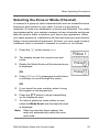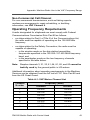
1
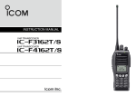
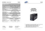
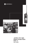
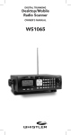
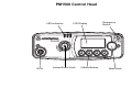
PM1500 Control Head
LED Indicators
GCAI
LCD Display
Volume/Power Knob
4 Menu Buttons
Emergency
Button
Mode Knob
PM1500
User Guide
Mobile Radio
This declaration is applicable to your radio only if your radio is labeled
with the FCC logo shown below.
DECLARATION OF CONFORMITY
Per FCC CFR 47 Part 2 Section 2.1077(a)
Responsible Party
Name: Motorola, Inc.
Address: 8000 West Sunrise Boulevard
Plantation, FL 33322 USA
Phone Number: 1-888-567-7347
Hereby declares that the product:
Model Name: PM1500
conforms to the following regulations:
FCC Part 15, subpart B, section 15.107(a), 15.107(d) and section 15.109(a)
Class B Digital Device
As a personal computer peripheral, this device complies with Part 15 of the FCC
Rules. Operation is subject to the following two conditions:
1. this device may not cause harmful interference, and
2. this device must accept any interference received, including interference that
may cause undesired operation.
Note: This equipment has been tested and found to comply with the limits for a
Class B digital device, pursuant to part 15 of the FCC Rules. These limits are
designed to provide reasonable protection against harmful interference in a
residential installation. This equipment generates, uses and can radiate radio
frequency energy and, if not installed and used in accordance with the
instructions, may cause harmful interference to radio communications.
However, there is no guarantee that interference will not occur in a particular
installation.
If this equipment does cause harmful interference to radio or television reception,
which can be determined by turning the equipment off and on, the user is
encouraged to try to correct the interference by one or more of the following
measures:
• Reorient or relocate the receiving antenna.
• Increase the separation between the equipment and receiver.
• Connect the equipment into an outlet on a circuit different from that to which
the receiver is connected.
• Consult the dealer or an experienced radio/TV technician for help.
PM1500 Mobile Radio with Control Head
ii
Product Safety and RF Exposure Compliance
!
Caution
Before using this product, read the operating instructions for safe
usage contained in the Product Safety and RF Exposure booklet
enclosed with your radio.
ATTENTION!
This radio is restricted to occupational use only to satisfy FCC RF energy
exposure requirements. Before using this product, read the RF energy
awareness information and operating instructions in the Product Safety and RF
Exposure booklet enclosed with your radio (Motorola Publication part number
6881095C99) to ensure compliance with RF energy exposure limits.
Computer Software Copyrights
The Motorola products described in this manual may include copyrighted Motorola
computer programs stored in semiconductor memories or other media. Laws in the
United States and other countries preserve for Motorola certain exclusive rights for
copyrighted computer programs, including, but not limited to, the exclusive right to copy
or reproduce in any form the copyrighted computer program. Accordingly, any
copyrighted Motorola computer programs contained in the Motorola products described
in this manual may not be copied, reproduced, modified, reverse-engineered, or
distributed in any manner without the express written permission of Motorola.
Furthermore, the purchase of Motorola products shall not be deemed to grant either
directly or by implication, estoppel, or otherwise, any license under the copyrights,
patents or patent applications of Motorola, except for the normal non-exclusive license
to use that arises by operation of law in the sale of a product.
Documentation Copyrights
No duplication or distribution of this document or any portion thereof shall take place
without the express written permission of Motorola. No part of this manual may be
reproduced, distributed, or transmitted in any form or by any means, electronic or
mechanical, for any purpose without the express written permission of Motorola.
Disclaimer
The information in this document is carefully examined, and is believed to be entirely
reliable. However, no responsibility is assumed for inaccuracies. Furthermore, Motorola
reserves the right to make changes to any products herein to improve readability,
function, or design. Motorola does not assume any liability arising out of the
applications or use of any product or circuit described herein; nor does it cover any
license under its patent rights, nor the rights of others.
MOTOROLA, the Stylized M Logo, and FLASHport are registered in the U.S. Patent &
Trademark Office. All other product or service names are the property of their
respective owners.
© Motorola, Inc. 2006. Printed in the U.S.A. 03/06.
iii
Notations Used in This Manual
Throughout the text in this publication, you will notice the use of WARNING,
CAUTION, and Note notations. These notations are used to emphasize that
safety hazards exist, and care that must be taken or observed.
!
WARNING
WARNING: An operational procedure, practice, or other
condition, which might result in injury or death if not carefully
observed.
!
CAUTION
CAUTION: An operational procedure, practice, or other
condition, which might result in damage to the equipment if not
carefully observed.
Note:
Note: An operational procedure, practice, or other condition,
which is essential to emphasize.
The following special notations identify certain items:
Example
Description
Programmable button or > Buttons and keys are shown in bold print or as a key
symbol.
CALL
Menu items (softkeys) are similar to the way they
appear on the radio’s display.
PM1500 Mobile Radio with Control Head
iv
Notes
v
Contents
PM1500 Control Head . . . . . . . . . . . . . . . . . . . . . . . . . . i
Declaration of Conformity .................................................................. ii
Computer Software Copyrights .........................................................iii
Documentation Copyrights ................................................................iii
Disclaimer .........................................................................................iii
Notations Used in This Manual ........................................................ iv
Introduction . . . . . . . . . . . . . . . . . . . . . . . . . . . . . . . . . . 1
Using Your Radio: The Basics .......................................................... 1
Getting Started .................................................................................. 2
Major Radio Components ................................................................. 4
The PM1500 Radio ..................................................................... 4
The Control Head ....................................................................... 4
Operating Your Control Head ............................................................ 6
Turning On the Radio ............................................................... 6
Setting the Volume ................................................................... 7
Adjusting the Display/Keypad Backlight Dim Level .................... 7
Keypad Microphone Option ........................................................ 7
Conventional Channels .............................................................. 8
Field Programming ..................................................................... 8
Display Status ................................................................................... 8
Feature Control ................................................................................. 8
Interpreting Radio Status Indicators .................................................. 9
Status Annunciators ................................................................... 9
LED Indications ........................................................................ 10
Alert Tones ............................................................................... 10
Basic Operating Procedures . . . . . . . . . . . . . . . . . . . 13
Basic Functions ............................................................................... 13
Monitoring Conventional Modes ..................................................... 14
Selecting the Zone or Mode (Channel) ........................................... 15
Receiving on a Conventional Mode .......................................... 16
Adjusting the Squelch Level ............................................................ 16
Transmitting on Conventional Modes ....................................... 17
Time-Out Timer ........................................................................ 17
General Radio Features . . . . . . . . . . . . . . . . . . . . . . . 18
Often-Used Features ....................................................................... 18
Emergency Call and Alarm ............................................................. 19
Initiating an Emergency Alarm .................................................. 19
PM1500 Mobile Radio with Control Head
vi
Initiating an Emergency Call and Alarm ....................................20
Special Considerations for Emergencies ..................................20
Types of Scan ..................................................................................21
Types of Scan Lists ...................................................................21
Types of Scanning ....................................................................21
Turning Scan On or Off .............................................................22
Deleting Nuisance Modes .........................................................23
Hang Up Box (HUB) ..................................................................24
Optional External Alarms (Horn and Lights) ....................................24
Activating the External Alarm(s) ................................................24
Receiving a Call While Alarms Are Turned On .........................25
PTT-ID (For MDC and DTMF Modes only) ......................................26
Call Alert ..........................................................................................26
Sending a Call Alert .................................................................27
Conventional Radio Features . . . . . . . . . . . . . . . . . . 29
Features Used in Conventional Operation ......................................29
Smart PTT .......................................................................................30
Conventional Talkgroup Calls ..........................................................31
Conventional Talkaround .................................................................32
Talk Direct (Mobile-To-Mobile) ..................................................32
Selective Call ...................................................................................33
Answering a Selective Call .......................................................33
Initiating a Selective Call ...........................................................34
Viewing Your Unit ID Number ...................................................35
Editing a Unit ID Number in the List ..........................................35
Editing a Name in the List .........................................................36
Troubleshooting . . . . . . . . . . . . . . . . . . . . . . . . . . . . . 38
Accessories. . . . . . . . . . . . . . . . . . . . . . . . . . . . . . . . . 39
Antennas .........................................................................................39
Cables .............................................................................................40
Microphones ....................................................................................40
Miscellaneous ..................................................................................41
Speakers ..........................................................................................41
Trunnion Kits ....................................................................................41
vii
Appendix: Maritime Radio Use in the VHF Frequency
Range . . . . . . . . . . . . . . . . . . . . . . . . . . . . . . . . . . . . . . 42
Special Channel Assignments ......................................................... 42
Emergency Channel ................................................................. 42
Non-Commercial Call Channel ................................................. 43
Operating Frequency Requirements ............................................... 43
Glossary . . . . . . . . . . . . . . . . . . . . . . . . . . . . . . . . . . . . 46
Commercial Warranty and Service . . . . . . . . . . . . . . 49
Limited Warranty ............................................................................. 49
Service ............................................................................................ 53
Index . . . . . . . . . . . . . . . . . . . . . . . . . . . . . . . . . . . . . . . 55
PM1500 Mobile Radio with Control Head
viii
Notes
ix
Introduction
Using Your Radio: The Basics
This chapter gives you the basic knowledge you need in order to use
your radio. The following topics are covered:
• Getting Started (page 2)
• Major Radio Components (page 4)
• Operating Your Control Head (page 6)
• Turning On the Radio (page 6)
• Setting the Volume (page 7)
• Turning the Display/Keypad Light On or Off (page 7)
• Display Status (page 8)
• Feature Control (page 8)
• Interpreting Radio Status Indicators (page 9)
PM1500 Mobile Radio with Control Head
1
Introduction
Getting Started
The PM™ 1500 Analog Mobile Radio is among the most
sophisticated two-way radios available. It can operate in the following
frequency ranges:
VHF
UHF
136-174 MHz
380-470 MHz
These channels provide maximum communications capability under
varying operating conditions.
The PM1500 Mobile Radio can include an optional RS-232 data port
to interface with external devices, such as certain laptop computers.
2
Introduction
Note: In this manual—
Your PM1500 Mobile Radio utilizes Motorola’s revolutionary
FLASHport™ technology. This allows your radio’s capabilities to be
flexible, because FLASHport makes it possible to add software that
drives these capabilities both at the time of purchase and later on.
Similar to how a computer can be loaded with different software, your
radio’s features and capabilities can be upgraded with software.
FLASHport allows you to add software to your radio as your needs
change and as technology advances, making your radio investment
go further.
FLASHport is the future of radio communications, and it’s yet another
example of Motorola’s commitment to your satisfaction.
PM1500 Mobile Radio with Control Head
3
Introduction
Major Radio Components
Your radio has two major components: the radio unit installed in your
vehicle and the control head that is used to activate various radio
features. You may also have radio accessories installed based on the
specific configuration of your radio.
This user guide describes how to use your radio and its control head.
The foldout page inside the back cover of this guide contains an
illustration of the control head showing all the controls and
programmable buttons situated on the control head. Keep this foldout
open as a reference as you review the procedures in this user guide.
The PM1500 Radio
The PM1500 radio unit contains a receiver, a transmitter, and
associated internal circuitry. The radio is programmed by your system
manager to meet your specific needs and/or those of your workgroup.
The Control Head
The control head that came with your PM1500 radio has the following
features (refer to the foldout at the back of this user guide):
• Power On/Volume Knob: Used to turn the radio on or off and
also to adjust the volume.
• One-line, 8-character-per-line, liquid-crystal display (LCD):
Shows alphanumeric messages or feature information as you
use your radio. Also displays annunciators above the character
lines, indicating the status of certain radio functions (see page
7).
RESP
EXIT
• Mode Knob: Used to rotate through the list of available
options, and also acts as a channel selector.
4
Introduction
• Emergency Button: Programmed as the emergency button by
default but can be custom programmed as any other feature.
• LED indicator: Green/red/yellow light-emitting diode that
indicates radio status as you operate various features (see
page 9).
• Four Programmable Menu Buttons: Check with your system
manager for information on how these buttons have been
programmed. Use the foldout at the back of this manual to
record the functions that have been programmed to each
button.
• PTT button on mic: Pressed to transmit on the displayed
mode and released to receive.
PM1500 Mobile Radio with Control Head
5
Introduction
Operating Your Control Head
Your control head is designed for ease of use and flexibility of feature
control. Before operating the radio, familiarize yourself with the
various controls, indicators, and alert tones. Refer to the foldout
diagrams in the front and back of this manual for your particular
control head.
Turning On the Radio
Do the following:
•
To turn the radio on, push the Volume/Power knob on the
control head to turn it on.
After a short time, the red, green and yellow LEDs light up, indicating
that the radio is powering up.
The display then shows PM 1500.
When the radio is fully powered on, the Zone and Channel text and
menu items are displayed. The backlight will turn on to the last
selected dim level.
Note: Pressing the Power/Volume Knob before the LEDs light up
will be ignored.
Pressing the power button anytime after the LEDs light up
will TURN OFF the radio.
Note: If FL ##/## appears in the display, the radio will not function
until the condition has been corrected.
If ERR ##/## appears, some non-critical data has been
changed. If either of these displays appear, if the display
goes blank, or if the unit appears to be locked up, refer to the
“Troubleshooting” section.
6
Introduction
Setting the Volume
Rotate the Volume knob clockwise to increase the volume and
counterclockwise to decrease the volume.
Adjusting the Display/Keypad Backlight Dim Level
The display light is useful when you need to read the information on
the display and locate keys on the keypad in less than optimal
lighting conditions (for example, during night time).
To adjust the display and keypad light: Press the DIM softkey, which
is one of the four of the programmable menu buttons.
The Control Head ships from the factory with the backlight set to
HIGH.
Keypad Microphone Option
When accessing a feature on the radio, use the left or right
toggles on the navigation key to access further options within
the menu.
If you cannot locate a menu item, it may not be programmed, or
it may not apply to the radio’s current setting.
The keypad also enables you to use certain capabilities within
features such as Call Alert and Selective Call. These
capabilities are described in detail within the appropriate
sections of this manual.
Note: The checkmark and X buttons on the keypad microphone
are for future use and not currently used by the radio.
PM1500 Mobile Radio with Control Head
7
Introduction
Conventional Channels
Conventional channels consist of a transmit and receive frequency
pair, and associated squelch code pair, and a time-out timer value.
See “Conventional Radio Features” on page 29.
Field Programming
Other radio features may be slaved to the selected mode by field
programming. This mode slaving means that the radio is
preprogrammed to automatically give you the proper operation for
each mode you select.
You may use the control head to program your own mode names.
The names you assign are clearly shown in the alphanumeric display.
You can see all the key operating information, including the mode
selected or being scanned, and the on/off status of various features.
The operating conditions are shown either by the display or by visual/
audio indicators, or by both.
Display Status
The control head display indicates your selected mode, or the
currently active receive mode.
Feature Control
You can turn the various radio features on or off, change modes, and
adjust the volume.
To exit a feature, such as call, press the EXIT or HOME button
located on the keypad mic.
8
Introduction
Interpreting Radio Status Indicators
Your radio has three types of status indicators:
• Status annunciators that appear on the display
• LED indicators
• Alert tones
Status Annunciators
These are small icons that appear on the display above the channel
name indicating status as you operate various radio features.
Annunciator
Indication
C
Carrier Squelch
All active traffic on the selected channel in being
monitored.
When not displayed, traffic is not open to
monitoring.
F
Call Received
Flashes when a Selective Call, Call Alert is
received.
G
Scan
The radio is scanning a preprogrammed list of
channels/modes for activity.
H
Priority Scan
Indicates scanning of a priority mode (flashing for
Priority 1 Mode; solid for Priority 2 mode).
R
Low Tx Power Level
Transmission Power is low. (By default, the radio
transmission power is set too high, at which state
this icon will not show up.)
J
Direct/Talkaround
When on, indicates your are talking directly to
another radio.
When off, you are talking through a repeater.
PM1500 Mobile Radio with Control Head
9
Introduction
Annunciator
Indication
K
View/Program Mode
The radio is in the view or program mode.
(flashing for program mode; solid for view mode.)
C
In-Call User Alert
Voice muting has been activated as radio is
receiving.
LED Indications
The LED indicator on the front of the control head indicates
operational status as you use various features:
LED State
Indication
Continuous RED when you
press PTT button to transmit
Normal transmission
YELLOW
Channel activity is present
GREEN
Receiving a call or page
Alert Tones
Your radio uses alert tones to inform you of radio conditions.
Tone Type
Short,
low pitched
tone
Indication
Action
Unsuccessful power-up. Radio
failed self-test. Radio not ready
for use.
Contact your
service
representative.
Invalid (bad) key press. A key
-
press was rejected.
Time-out timer warning.
Transmission time will expire in
four seconds.
10
-
Introduction
Tone Type
Indication
Action
Short, medium Valid (good) key press. A key
pitched tone
press was accepted.
-
Pressed emergency button to
-
enter emergency. Emergency
entered.
Short, high
pitched tone
Successful power-up. Radio
Continuous,
low pitched
tone
Transmit on receive-only mode.
-
passed self-test.
Pressed PTT button on receive
Release PTT
button.
only mode.
Transmit inhibit on busy mode.
Pressed PTT button while mode
is busy
Invalid mode. An invalid or
-
unprogrammed operation.
Time-out timer timed out.
Continuous,
medium
pitched tone
Transmission terminated.
Release PTT
button.
Emergency alarm/call exit.
-
Exiting.
PM1500 Mobile Radio with Control Head
11
Introduction
Tone Type
Indication
Action
-
Single,
medium
pitched tones
followed by
group of four
medium
pitched tones
Your page has been received by
Group of two
medium
pitched tones
Selective Call received.
-
Group of four
medium
pitched tones
every five
seconds
Call Alert (page) received by
-
Four short,
medium
pitched tones
Emergency alarm
Continuous,
low pitched
tone
No Emergency. Current
conventional system does not
have emergency enabled. No
emergency tone.
-
Group of two
high pitched
tones
Fast ring in Selective call.
-
12
the target radio.
your radio.
-
acknowledged.
System is searching for target
radio.
Basic Operating Procedures
Basic Functions
This chapter shows you how to access the radio’s basic functions and
includes the following topics:
•
Monitoring Conventional Modes (page 14)
•
Selecting the Zone or Mode (page 15)
•
Receiving on Conventional Modes (page 16)
•
Adjusting Squelch Settings (page 16)
•
Selecting the Transmit Level (page 17)
•
Transmitting on Conventional Modes (page 17)
PM1500 Mobile Radio with Control Head
13
Basic Operating Procedures
Monitoring Conventional Modes
To monitor conventional modes, do the following:
1
Press the preprogrammed Monitor button.
2
The display shows MON ON and the carrier
squelch annunciator is turned on indicating
that the squelch circuit has been opened,
allowing you to monitor all the traffic on the
channel.
C
MON ON
To cancel monitoring
1
Press the preprogrammed Monitor button.
2
The display shows MON OFF and the carrier
squelch annunciator is turned off.
14
MON OFF
Basic Operating Procedures
Selecting the Zone or Mode (Channel)
A channel is a group of radio characteristics such as transmit/receive
frequency pairs stored in your radio. A zone is a grouping of
channels. A mode is a combination of zones and channels. Your radio
is programmed by your system manager to have channels and zones
that you need in order to perform your day-to-day operations. When
your radio powers up, it defaults to the last selected zone and channel
before it was powered off previously. At times, you may need to select
a different zone or channel to transmit or receive on, as follows:
1
Press the D button below zone.
2
The display shows the current zone and
mode.
3
Rotate the Mode Knob until the desired zone
is displayed
OR
4
Police 1
SCAN TGRP ZONE
H/L
Police 2
Police 1
Press ZNUP or ZNDN preprogrammed buttons
or softkeys to scroll through the zones.
OR
5
If you know the zone number, enter it using
the keypad on the keypad mic.
6
Press the PTT button to begin transmitting
on the displayed zone.
7
To select a particular mode within a zone,
rotate the Mode Knob until the desired mode
is displayed.
Note: After the selection timer expires, the
radio will automatically select the zone
and mode.
PM1500 Mobile Radio with Control Head
15
Basic Operating Procedures
Receiving on a Conventional Mode
Follow these steps to receive while on conventional mode:
1
Select a desired zone and mode.
2
When you hear a transmission, use the Volume Knob to adjust
the volume to a comfortable listening level.
Your radio is now set to receive on the selected mode.
Note: If the mode is busy when your radio is receiving a clear
signal, the yellow LED blinks continuously until the mode is
not in use.
Adjusting the Squelch Level
Your radio’s ability to transmit or receive signals varies as you move
away from or close to your base station. You can adjust your radio’s
squelch to improve its ability to receive transmissions.
Do the following:
1
Press SQL.
The display shows SQL XX, where XX is a squelch level setting
of 0 to 15.
2
To scroll to the desired squelch setting, choose on the following:
Rotate the Mode Knob
OR
Press the + or - softkeys
OR
Use the navigation keys on the keypad mic.
3
16
Press the EXIT softkey to return to the selected channel.
Basic Operating Procedures
Transmitting on Conventional Modes
Follow these steps to transmit while on a conventional mode:
1
Select a desired zone and mode.
2
When a mode becomes available, press and hold the PTT
button to transmit. Speak clearly into the mic.
Note: If you try to transmit on a receive-only mode, you will hear a
continuous low-pitched (“invalid mode”) tone.
Time-Out Timer
This feature limits the amount of time you can continuously transmit.
Your system manager can program the timer for up to 465 seconds at
15-second intervals. PM1500 radios are programmed at the factory to
time-out after 60 seconds.
Note:
You hear a low-pitched alert tone four seconds before your
transmission is about to expire.
If you hold down the PTT button longer than the programmed time,
you hear a continuous, low-pitched tone. This tone ceases to sound
when you release the PTT button, and you are not allowed to
transmit.
PM1500 Mobile Radio with Control Head
17
General Radio Features
Often-Used Features
This chapter shows you how to access the most frequently used
features. The following topics are covered:
18
•
Emergency Call and Alarm (page 19)
•
Scan Operation (page 21)
•
Optional External Alarms (Horn and Lights) (page 24)
•
Push-To-Talk Identification (PTT-ID) (page 26)
•
Call Alert Page (page 26)
General Radio Features
Emergency Call and Alarm
The emergency call and alarm features allow you to have priority
channel access to the dispatcher in an emergency situation.
The desired type of emergency feature—alarm, call, call and alarm —
can be preprogrammed by a qualified radio technician.
The radio must be turned on to activate any emergency feature.
Initiating an Emergency Alarm
The emergency alarm feature sends a data transmission to alert the
dispatcher of your emergency condition and identify your unit ID.
Press the emergency button.
A tone sounds and the display alternates EMERGNCY with the
current zone/channel.
A dispatcher acknowledgment ACK RCVD display follows.
The radio automatically returns to normal operation. No further
action is required.
PM1500 Mobile Radio with Control Head
19
General Radio Features
Initiating an Emergency Call and Alarm
If the radio has both emergency call and alarm features, it
automatically proceeds to the call mode after the alarm is
acknowledged.
1
Press the emergency button to activate the emergency call/
alarm feature.
The display begins alternating EMERGNCY with the current zone/
channel.
A dispatcher acknowledgment (four high-pitched tones) follows,
accompanied by an ACK RCVD display.
2
Press the PTT button and announce your emergency.
3
To exit from the emergency state altogether, press and hold the
emergency button until a tone sounds.
The alternating EMERGNCY display disappears, and the radio
returns to normal operation.
Note: Turning the radio off also cancels the emergency state.
Special Considerations for Emergencies
•
If you press the emergency button while in a mode that has no
emergency capability, a low-pitched tone sounds.
•
If the emergency alarm is not acknowledged, a tone sounds and
the display shows NO ACK.
•
If you press the emergency button, then change to a mode that
has no emergency capability, a NO EMERG display alternates with
the mode name display, and a continuous low-pitched tone
sounds until a valid emergency mode is selected or until the
emergency is cancelled.
•
When an emergency is active, changing to another mode where
emergency is enabled causes an emergency alarm and/or
emergency call to be active on the new mode.
20
General Radio Features
Types of Scan
Your PM1500 radio can monitor traffic on many different channels by
scanning a list containing as many as 15 conventional or trunked
modes. Up to 2 different scan lists are available per radio. A special
package configured by your service provider can allow up to a
maximum of 20 scan lists. Setting the modes to be scanned is
programmed in advance by a qualified radio technician.
Types of Scan Lists
List Type
Conventional
Description
Only conventional modes are in the
list.
Types of Scanning
Scan Type
Description
Automatic (autoscan)
When selected, a channel with
autoscan automatically begins
scanning its associated scan list. The
radio continues auto scanning until
you select a channel without autoscan
enabled.
Operator-Selectable
Scan can be programmed, by a
qualified radio technician, to be
selected either from a menu or by a
preprogrammed Scan button.
Note: You cannot turn scan off on a mode that has autoscan
enabled.
Note: Scan lists stay in memory when you turn scan off, turn the
radio off, or disconnect the radio from the battery.
PM1500 Mobile Radio with Control Head
21
General Radio Features
Turning Scan On or Off
1
Press button below SCAN.
OR
Police 1
SCAN
Alternatively press the preprogrammed
Scan button.
2
The display shows SCAN ON if previously
SCAN OFF was selected and the scan
indicator is turned on.
SCAN ON
OR
3
22
The display shows SCAN OFF if previously
SCAN ON was selected and the scan
indicator is turned on.
SCAN OFF
General Radio Features
Deleting Nuisance Modes
During scanning, you can temporarily delete modes you do not want
to hear. This feature must be preprogrammed by your system
manager.
Follow these steps to delete a nuisance mode:
1
When the radio is locked onto the mode you want to delete,
Press the preprogrammed Nuisance Delete button.
OR
Press the NUIS softkey to delete the mode.
A valid key-press chirp tone sounds. The mode is deleted and
the radio continues to scan the remaining modes
Note: You cannot delete priority modes and the designated
transmit channel.
2
To resume scanning the deleted mode, press scan off and then
back on again.
OR
Turn the power off and then back on again.
PM1500 Mobile Radio with Control Head
23
General Radio Features
Hang Up Box (HUB)
To temporarily suspend Scan Mode operation, remove the
microphone from the Hang Up Box (HUB). You are allowed to use the
microphone while scan is suspended. Priority Member scanning is
not suspended, however. This feature applies to all Scan Lists and
Scan Types. Scan is resumed once the microphone is returned to the
holding clip and the preprogrammed hang time has elapsed.
Note: Priority Scan List members are continuously scanned only
when the Scan List, Designated Tx Member field is set to
“Talkback” in the radio programming. Otherwise, all scan
mode operation is suspended.
Optional External Alarms (Horn and Lights)
All control heads can be equipped for external alarms (horn and
lights) that are activated when a Call Alert page or Selective Call, is
received.
These features are useful when you must leave the vehicle, but need
to receive any incoming messages.
The radio always powers up with the horn and lights feature enabled.
Activating the External Alarm(s)
Non-Permanent Horn and Lights
1
Press the H/L softkey momentarily.
If necessary use theor buttons on the keypad mic to
access other options within the menu.
The last selected alarm(s) are enabled, and the display
alternately shows the enabled alarm(s), then the selected
mode.
2
24
Press the H/L softkey a second time to turn off the alarm(s).
General Radio Features
Receiving a Call While Alarms Are Turned On
When a call is received, the vehicle’s horn sounds for four seconds,
and/or the car lights turn on for 60 seconds. The time interval can be
modified by a qualified radio technician.
The display alternates between the type of call received (CALL or
PAGE) and the selected mode name.
Turning Off Non-Rearmable External Alarm
1
To turn off the external alarm(s), press the PTT button or any
control-head button.
Note: Pressing the CALL or PAGE softkey will turn off the external
alarm(s) and place you directly in that feature.
The Volume knob and the DIM button have no effect on the
state of the external alarm(s).
2
To rearm the horn and lights feature, press the H/L softkey
momentarily.
Turning Off Rearmable External Alarms
To turn off the external alarm(s), press the PTT button or any
control head softkey or button other than the H/L softkey.
Pressing CALL or PAGE softkey turns off the external alarm(s)
and places you directly in that feature. When the external
alarm(s) are turned off, they will be automatically rearmed.
Note: Pressing the H/L softkey turns off the external alarm(s) and
exits the horn and lights feature. To re-arm the feature, press
the H/L softkey momentarily.
The Volume knob and the DIM have no effect on the state of
the external alarms.
PM1500 Mobile Radio with Control Head
25
General Radio Features
PTT-ID (For MDC and DTMF Modes only)
This stands for Push-to-Talk ID. This feature is programmed as
needed for each channel by your system manager.
If this feature is made available for your talkgroup, it allows you to see
the ID number of the radio from which you are receiving a
transmission. This ID could be up to eight characters in length and is
shown on your display as well as on your dispatcher’s display.
In addition, your radio ID number is automatically sent when you
transmit.
Call Alert
The Call Alert feature allows a radio to selectively alert another radio,
and to determine whether or not that radio received the alert. A Call
Alert page can be initiated, depending on the signaling (MDC, QCII or
DTMF) that has been preprogrammed on the channel, after an
unsuccessful Selective Call or as a separate feature.
The PM1500 Controller Head is capable of responding to a Call Alert
initiated by another radio. It features a unique list of up to 100
preprogrammed ID numbers. A name can be assigned to each ID in
the list for your convenience.
26
General Radio Features
Sending a Call Alert
1
Press the PAGE softkey.
The Call Alert indicator lights and a valid-key chirp sounds.
For MDC, the display shows the last transmitted/received unit ID
number.
For DTMF, it shows the last transmitted ID.
For QCII, it shows the first entry in the call list.
2
Select a radio in one of the following ways:
•
From the ID number list:
–
Do nothing if you want to call the unit ID currently
displayed.
OR
–
Use the prestored list by using the mode knob or
navigation keys on the keypad mic to locate the name/ID
you want to call.
OR
–
Enter, using the keypad on the keypad mic, the ID of the
desired unit.
Note: Using the keypad to enter the ID of another unit can only be
accomplished from the first display shown when Page was
entered. If the list has been entered, scroll to the first display.
3
Press the SEL softkey or the microphone PTT button.
The display changes to PLS WAIT.
PM1500 Mobile Radio with Control Head
27
General Radio Features
4
Choose one of the following:
•
When the called radio acknowledges the page, four
additional tones sound and the display changes to ACK
RCVD.
The radio returns to normal operation.
•
If, after six seconds, the called unit fails to acknowledge the
alert, a low-pitched tone sounds and the display changes to
NO ACK.
Try again by pressing the PTT button or the SEL softkey,
OR
Press the HOME button to exit.
28
Conventional Radio Features
Features Used in Conventional Operation
This chapter shows you how to access features available in
conventional operation. The following topics are covered:
• Smart PTT (page 30)
• Conventional Talkgroup Calls (page 31)
• Conventional Talkaround (page 32)
• Selective Calls (page 33)
29
Conventional Radio Features
Smart PTT
Smart PTT is a per-mode feature that gives the system manager
better control of radio operations. When smart PTT is enabled in your
radio, you will not be able to transmit on an active mode. If you try to
transmit (press the PTT button) on a busy or active smart PTT
channel, a continuous tone sounds until you release the PTT button,
and the transmission is inhibited.
The yellow LED lights when the radio is receiving to indicate that the
mode is busy.
Three radio-wide variations of smart PTT can be enabled on your
radio:
Transmit Inhibit on
Busy Mode with
Carrier
You will not be able to transmit if any
activity is detected on the mode.
Transmit Inhibit on
Busy Mode with
Wrong Squelch Code
You will not be able to transmit on an
active mode that has a squelch code other
than your own.
Quick-Key Override
You can override either of the two previous
transmit-inhibit states by quick-keying the
radio (two quick PTT button presses).
30
Conventional Radio Features
Conventional Talkgroup Calls
The Talkgroup Select feature allows you to manually select any one
of the available talkgroups.
1
Press the TGRP softkey.
The display changes to show the last selected talk group.
2
Rotate the Mode Knob to choose a different talkgroup.
3
Press the SEL softkey to save the talkgroup.
The radio returns to the home display.
Note: To select the default talkgroup, press the SEL softkey while
the radio displays PSET.
Selecting the PSET softkey causes the radio to return to its
preprogrammed talkgroup.
To abort the talkgroup menu, press the HOME button or the
PTT button:
- Pressing the HOME exits the talkgroup select menu
without saving the selected talkgroup choice.
- Pressing the PTT button exits the menu without saving
the selected talkgroup and allows the radio to transmit.
Note: If the encryption key slaved to the new talkgroup is erased,
the display shows KEY FAIL and a momentary tone is
generated. If the encryption key that is slaved to the new
talkgroup is not allowed, the display shows ILGL KEY and a
momentary tone is generated.
PM1500 Mobile Radio with Control Head
31
Conventional Radio Features
Conventional Talkaround
Talk Direct (Mobile-To-Mobile)
To talk directly to another unit without going through the conventional
repeater system:
1
Press the DIR softkey momentarily.
The DIR indicator lights, indicating that the radio is now
transmitting directly to another unit.
2
To return to repeater operation, press the DIR softkey again.
The DIR indicator goes out.
Note: A conventional personality can be configured to always
transmit on the direct mobile-to-mobile frequency. In this
case, the DIR indicator is lit continuously while the mode is
selected.
32
Conventional Radio Features
Selective Call
The Selective Call feature not only allows you to carry on a
conversation that is heard only by the two parties involved, but also
enables you to determine whether the unit you are calling is in
service.
The PM1500 Control Head is capable of responding to a Selective
Call initiated by another radio. It features a unique list of
preprogrammed ID numbers. This depends on the signaling type
(MDC, QCII or DTMF) that has been programmed on the channel. A
name may be assigned to each ID in the list for your convenience.
Answering a Selective Call
When a Selective Call is received, two high-pitched tones sound
and the display alternates between CALL RCV and the home display.
1
Press the CALL softkey within 20 seconds of receiving the call.
(This time is programmable by a qualified radio technician.)
The display shows the ID number of the calling unit.
2
To respond to the call, press the PTT button and talk.
If 20 seconds pass before you press the CALL softkey, you will
not respond privately to the call just received. Instead, when
you press the CALL softkey, you enter the Selective Call state,
as described in “Selective Call” on page 33.
Note: If you do not press the CALL softkey before pressing the
PTT button, your conversation will be heard by all members
of the talk group.
PM1500 Mobile Radio with Control Head
33
Conventional Radio Features
Initiating a Selective Call
To initiate a Selective Call, select a unit to call, then place the call.
1
Press the CALL softkey.
2
Select a unit in one of the following ways:
•
From the ID number list:
–
Do nothing if you want to call the unit ID currently
displayed.
OR
–
Use the prestored list by turning the Mode knob to locate
the name/ID you want to call.
OR
–
Enter, using the keypad on the keypad mic, the ID of the
desired unit.
Note: Using the keypad to enter the ID of another unit can only be
accomplished from the first display shown when CALL was
entered. If the list has been entered, scroll to the first display.
Press the numeric keys on the keypad mic to enter the digit
of the location number to access a preprogrammed call ID.
3
Press the microphone PTT button.
A telephone-type ringing sounds if the unit you are calling is in
service.
4
When the receiving unit answers, identify yourself and begin
your Selective Call.
5
To return to normal operation, press the HOME button.
Note: If you do not press the HOME button to hang up, your unit
will remain in the Selective Call state with the other unit. You
will miss all subfleet traffic.
34
Conventional Radio Features
Viewing Your Unit ID Number
1
Press the CALL softkey momentarily to select the Selective Call
feature.
2
Do one of the following:
•
Use the left navigation key on the keypad mic or the Mode
Knob to locate the MY ID display.
OR
•
3
The display will alternate between MY ID and your ID
number.
To return to normal operation, press the HOME button.
Editing a Unit ID Number in the List
The Selective and Call Alert page features share the same prestored
list of units’ IDs.
1
Press and hold the CALL softkey to review the Call ID list.
2
Use the navigation keys to locate the list member you want to
change.
3
Press the NUM softkey to edit a number.
4
Use the keypad mic to update the entry.
5
When all the digits are entered, press the SAVE softkey to store
the new ID.
PM1500 Mobile Radio with Control Head
35
Conventional Radio Features
6
Repeat steps 2 through 5 until all the desired IDs have been
entered.
OR
Do one of the following:
•
Press the HOME button to return to normal radio operation.
OR
•
Press PTT to exit the feature.
Note: The maximum number of characters permitted in a text line
is 8.
Editing a Name in the List
The Selective Call and Call Alert page features share the same
prestored list of unit IDs.
1
Press and hold the CALL or PAGE softkey to enter the Call ID list.
2
Use the navigation keys on the keypad mic or the Mode Knob to
locate the list member you want to change.
OR
Use the numbered keys to go immediately to the location of a
member in the list. For example, press 2 to go to the second
member in the list; press 1 and 0 to go to the tenth member in
the list, and so on.
3
Press the NAME softkey to edit a name.
4
Change the characters or numbers using any of the numeric
keys (0 through 9) and special function keys (*, #) with the
keypad mic.
36
Conventional Radio Features
Note: The maximum number of characters permitted in a text line
is 8. If you try to add too many characters, you will hear a
low-pitched tone.
To edit, do any or all of the following:
•
Press the key of the desired character the number of times
shown in the table. For example, to enter the character C,
press the 2 key three times.
•
To leave a space in the text, press the up navigation key
on the keypad mic to move the blinking cursor to the next
character position, and then enter the next character.
•
To delete characters, press the down navigation key to
move backwards over existing characters.
When the last character on the display has been erased,
press the down navigation key again to leave the nameedit mode, without making any changes, and begin the
procedure again at step 2.
5
To save the changes, press and hold the SAVE softkey.
6
Repeat steps 2 through 5 until you have modified all the desired
names.
OR
Do one of the following:
•
Press the HOME button to return to normal radio operation.
OR
•
Press PTT to exit the feature.
PM1500 Mobile Radio with Control Head
37
Troubleshooting
The following are suggestions to assist you in troubleshooting
possible operating problems.
!
CAUTION
The cables that connect to the rear of the radio
could have live voltage on some of their pins.
Do not remove or reconnect these cables. Only
a qualified radio technician should perform this
task. Service performed by unauthorized personnel may cause the radio to transmit an
emergency alarm even if the unit is turned off.
If your radio is locked up or the display shows FL 01/90, turn the
radio off and then back on. If this does not correct the condition, take
the radio to a qualified radio technician for service.
If radio operation is intermittent, check with other persons using the
system for similar problems before taking the radio in for service.
If symptoms persist or, if your unit exhibits other problems, contact a
qualified radio technician.
38
PM1500 Mobile Radio with Control Head
Accessories
Motorola provides the following approved accessories to improve the
productivity of your PM1500 mobile two-way radio.
For a list of Motorola-approved antennas, batteries, and other
accessories, visit the following web site:
http://www.motorola.com/governmentandenterprise
Antennas
Part No.
Description
HAD4006_
VHF, 136–144 MHz, quarterwave whip,
roof mount
HAD4007_
VHF, 144–150.8 MHz, quarterwave,
roof mount
HAD4008_
VHF, 150.8–162 MHz, quarterwave,
roof mount
HAD4009_
VHF, 162–174 MHz, quarterwave, roof
mount
HAD4017_
VHF, 146-174 MHz, quarterwave
RAD4010_
VHF, 136–174 MHz, halfwave, roof
mount
HAE4003_
UHF, 450–470 MHz, quarterwave whip
HAE4011_
UHF, 450–470 MHz, 3.5 db, roof mount
HAE6010_
UHF, 380–433 MHz, 3.5 db gain
HAE6012_
UHF, 380–433 MHz, quarterwave whip
HAE6013_
UHF, 380–470 MHz, 2.0 db gain,
wideband
RAE4014_RB
UHF, 450–470 MHz, 5.0 db
39
Accessories
Cables
Part No.
Description
HKN4192_
Power, 20-ft., remote-mount
HKN6188_
Control head power cable (includes
ignition sense)
HKN6164_
Remote Mount Cable (CAN) - 40m (131 ft)
HKN6165_
Remote Mount Cable (CAN) - 35m (115 ft)
HKN6166_
Remote Mount Cable (CAN) - 23m (75 ft)
HKN6167_
Remote Mount Cable (CAN) - 15m (50 ft)
HKN6168_
Remote Mount Cable (CAN) - 10m (30 ft)
HKN6169_
Remote Mount Cable (CAN) - 5m (17 ft)
HKN6170_
Remote Mount Cable (CAN) - 3m (10 ft)
HKN6183_
Cable, CH Programming (RS-232)
Microphones
40
Part No.
Description
HMN1090_
Standard Mic
HMN4079_
Keypad Mic
HMN1089_
Water Resistant Mic
HLN1457_
Handset w/Hang up
Accessories
Miscellaneous
Part No.
Description
GKN6271_
Ignition Sense Cable
GLN7278_
PTT Footswitch
HKN4258_
External Alarm Cable
HMN1087_
Gooseneck PTT
HLN5113_
Emergency footswitch
HLN5131_
Emergency pushbutton switch
HLN6953_
Buzzer Kit 110 MA
TLN4533_
External Alarm Relay
Speakers
Part No.
Description
HSN4038_
7.5 W external
HSN4039_
13 W external
Trunnion Kits
Part No.
Description
HLN6909_
Quick-release, high-power
HLN6910_
Standard high-power
HKN6186_
Trunnion, CH Remote Mount
PM1500 Mobile Radio with Control Head
41
Appendix: Maritime Radio Use in the
VHF Frequency Range
Special Channel Assignments
Emergency Channel
If you are in imminent and grave danger at sea and require
emergency assistance, use VHF Channel 16 to send a distress call
to nearby vessels and the United States Coast Guard. Transmit the
following information, in this order:
1
“MAYDAY, MAYDAY, MAYDAY.”
2
“THIS IS _____________________, CALL SIGN __________.”
State the name of the vessel in distress 3 times, followed by the
call sign or other identification of the vessel, stated 3 times.
3
Repeat “MAYDAY” and the name of the vessel.
4
“WE ARE LOCATED AT _______________________.”
State the position of the vessel in distress, using any information
that will help responders to locate you, e.g.:
• latitude and longitude
• bearing (state whether you are using true or magnetic north)
• distance to a well-known landmark
• vessel course, speed or destination
5
State the nature of the distress.
6
Specify what kind of assistance you need.
7
State the number of persons on board and the number needing
medical attention, if any.
8
Mention any other information that would be helpful to
responders, such as type of vessel, vessel length and/or
tonnage, hull color, etc.
9
“OVER.”
10 Wait for a response.
11 If you do not receive an immediate response, remain by the radio
and repeat the transmission at intervals until you receive a
response. Be prepared to follow any instructions given to you.
42
PM1500 Mobile Radio with Control Head
Appendix: Maritime Radio Use in the VHF Frequency Range
Non-Commercial Call Channel
For non-commercial transmissions, such as fishing reports,
rendezvous arrangements, repair scheduling, or berthing
information, use VHF Channel 9.
Operating Frequency Requirements
A radio designated for shipboard use must comply with Federal
Communications Commission Rule Part 80 as follows:
•
on ships subject to Part II of Title III of the Communications Act,
the radio must be capable of operating on the 156.800 MHz
frequency
•
on ships subject to the Safety Convention, the radio must be
capable of operating:
•
•
in the simplex mode on the ship station transmitting
frequencies specified in the 156.025–157.425 MHz frequency
band, and
in the semiduplex mode on the two frequency channels
specified in the table below.
Note: Simplex channels 3, 21, 23, 61, 64, 81, 82, and 83 cannot be
lawfully used by the general public in US waters.
Additional information about operating requirements in the Maritime
Services can be obtained from the full text of FCC Rule Part 80 and
from the US Coast Guard.
Table A-1: VHF Marine Channel List
Frequency (MHz)
Channel
Number
Transmit
Receive
1
156.050
160.650
2
156.100
160.700
*
156.150
160.750
4
156.200
160.800
5
156.250
160.850
6
156.300
–
7
156.350
160.950
PM1500 Mobile Radio with Control Head
43
Appendix: Maritime Radio Use in the VHF Frequency Range
Table A-1: VHF Marine Channel List (Continued)
44
Frequency (MHz)
Channel
Number
Transmit
Receive
8
156.400
–
9
156.450
156.450
10
156.500
156.500
11
156.550
156.550
12
156.600
156.600
13**
156.650
156.650
14
156.700
156.700
15**
156.750
156.750
16
156.800
156.800
17**
156.850
156.850
18
156.900
161.500
19
156.950
161.550
20
157.000
161.600
*
157.050
161.650
22
157.100
161.700
*
157.150
161.750
24
157.200
161.800
25
157.250
161.850
26
157.300
161.900
27
157.350
161.950
28
157.400
162.000
60
156.025
160.625
*
156.075
160.675
62
156.125
160.725
63
156.175
160.775
*
156.225
160.825
65
156.275
160.875
66
156.325
160.925
Appendix: Maritime Radio Use in the VHF Frequency Range
Table A-1: VHF Marine Channel List (Continued)
Frequency (MHz)
Channel
Number
Transmit
Receive
67**
156.375
156.375
68
156.425
156.425
69
156.475
156.475
71
156.575
156.575
72
156.625
–
73
156.675
156.675
74
156.725
156.725
75
***
***
76
***
***
77**
156.875
–
78
156.925
161.525
79
156.975
161.575
80
157.025
161.625
*
157.075
161.675
*
157.125
161.725
*
157.175
161.775
84
157.225
161.825
85
157.275
161.875
86
157.325
161.925
87
157.375
161.975
88
157.425
162.025
*
Simplex channels 3, 21, 23, 61, 64, 81, 82, and 83 cannot be
lawfully used by the general public in US waters.
** Low power (1 W) only
*** Guard band
Note: A – in the Receive column indicates that the channel is transmit
only.
PM1500 Mobile Radio with Control Head
45
Glossary
Glossary
ACK
Acknowledgment of communication.
Call Alert
A one-way alert, with audio and/or display
messages.
Channel
A group of characteristics, such as transmit/
receive frequency pairs, radio parameters, and
encryption encoding.
Coded Squelch
Tone Private-Line™ or Digital Private-Line.
Used on conventional channels to make sure
you hear only the communication meant for
you.
Conventional
Typically refers to radio-to-radio
communications, sometimes through a
repeater. You share a frequency, or
frequencies, with other users without the aid of
a central controller to assign communication
channels. Therefore, you should monitor each
channel before transmitting to avoid interfering
with another user who may be transmitting.
Cursor
A visual tracking marker (a blinking line) that
indicates a location on the display.
Digital PrivateLine (DPL) Coded
Squelch
A continuous, sub-audible data signal,
transmitted with the carrier.
Dispatcher
An individual who has radio system
management duties.
FCC
Federal Communications Commission.
Hang Up
Disconnect.
46
Glossary
Home Display
The first display information after the radio
completes its self test.
LCD
Liquid-Crystal Display.
Mode
A programmed combination of operating
parameters; for example, a channel or
talkgroup.
Mode-Slaving
Radio programmed to automatically give the
proper operation for a given mode you have
selected.
Monitoring
(Conventional
Operation)
Press a programmed monitor button to listen to
another user active on the channel. This way,
you may be prevented from talking over
someone else’s conversation.
Push-To-Talk
(PTT) button
The PTT button engages the transmitter and
puts the radio in transmit (send) operation
when pressed. Press this button to transmit;
release it to receive.
Repeater
A conventional radio feature, in which you talk
through a receive/transmit facility (repeater)
that re-transmits received signals in order to
improve communications range and coverage.
RF
Radio Frequency. A part of the general
frequency spectrum between the audio and
infrared light regions (about 10 kHz to
10,000,000 MHz).
Squelch
The muting of audio circuits when received
signal levels fall below a pre-determined
threshold. With carrier squelch, you hear all
channel activity which exceeds the radio’s
preset squelch level.
PM1500 Mobile Radio with Control Head
47
Glossary
Talkgroup
An organization (or group) of radio users who
communicate with each other, using the same
communication path.
Tone Private-Line
(PL) Coded
Squelch
A continuous sub-audible tone transmitted with
the carrier.
Zone
A grouping of channels or talkgroups.
48
Commercial Warranty and Service
Limited Warranty
MOTOROLA COMMUNICATION PRODUCTS
I. WHAT THIS WARRANTY COVERS AND FOR HOW LONG:
MOTOROLA INC. (“MOTOROLA”) warrants the MOTOROLA
manufactured Communication Products listed below (“Product”)
against defects in material and workmanship under normal use and
service for a period of time from the date of purchase as scheduled
below:
CHIEF PM 1500 Mobile Units
Two (2) Year
Product Accessories
One (1) Year
Motorola, at its option, will at no charge either repair the Product (with
new or reconditioned parts), replace it (with a new or reconditioned
Product), or refund the purchase price of the Product during the
warranty period provided it is returned in accordance with the terms of
this warranty. Replaced parts or boards are warranted for the balance
of the original applicable warranty period. All replaced parts of
Product shall become the property of MOTOROLA.
This express limited warranty is extended by MOTOROLA to the
original end user purchaser only and is not assignable or transferable
to any other party. This is the complete warranty for the Product
manufactured by MOTOROLA. MOTOROLA assumes no obligations
or liability for additions or modifications to this warranty unless made
in writing and signed by an officer of MOTOROLA. Unless made in a
separate agreement between MOTOROLA and the original end user
purchaser, MOTOROLA does not warrant the installation,
maintenance or service of the Product.
MOTOROLA cannot be responsible in any way for any ancillary
equipment not furnished by MOTOROLA which is attached to or used
in connection with the Product, or for operation of the Product with
any ancillary equipment, and all such equipment is expressly
excluded from this warranty. Because each system which may use
the Product is unique, MOTOROLA disclaims liability for range,
coverage, or operation of the system as a whole under this warranty.
49
Commercial Warranty and Service
II. GENERAL PROVISIONS:
This warranty sets forth the full extent of MOTOROLA'S
responsibilities regarding the Product. Repair, replacement or refund
of the purchase price, at MOTOROLA’s option, is the exclusive
remedy. THIS WARRANTY IS GIVEN IN LIEU OF ALL OTHER
EXPRESS WARRANTIES. IMPLIED WARRANTIES, INCLUDING
WITHOUT LIMITATION, IMPLIED WARRANTIES OF
MERCHANTABILITY AND FITNESS FOR A PARTICULAR
PURPOSE, ARE LIMITED TO THE DURATION OF THIS LIMITED
WARRANTY. IN NO EVENT SHALL MOTOROLA BE LIABLE FOR
DAMAGES IN EXCESS OF THE PURCHASE PRICE OF THE
PRODUCT, FOR ANY LOSS OF USE, LOSS OF TIME,
INCONVENIENCE, COMMERCIAL LOSS, LOST PROFITS OR
SAVINGS OR OTHER INCIDENTAL, SPECIAL OR
CONSEQUENTIAL DAMAGES ARISING OUT OF THE USE OR
INABILITY TO USE SUCH PRODUCT, TO THE FULL EXTENT
SUCH MAY BE DISCLAIMED BY LAW.
III. STATE LAW RIGHTS:
SOME STATES DO NOT ALLOW THE EXCLUSION OR LIMITATION
OF INCIDENTAL OR CONSEQUENTIAL DAMAGES OR
LIMITATION ON HOW LONG AN IMPLIED WARRANTY LASTS, SO
THE ABOVE LIMITATION OR EXCLUSIONS MAY NOT APPLY.
This warranty gives specific legal rights, and there may be other
rights which may vary from state to state.
IV. HOW TO GET WARRANTY SERVICE:
You must provide proof of purchase (bearing the date of purchase
and Product item serial number) in order to receive warranty service
and, also, deliver or send the Product item, transportation and
insurance prepaid, to an authorized warranty service location.
Warranty service will be provided by Motorola through one of its
authorized warranty service locations. If you first contact the company
which sold you the Product, it can facilitate your obtaining warranty
service. You can also call Motorola at 1-888-567-7347 US/Canada.
50
Commercial Warranty and Service
V. WHAT THIS WARRANTY DOES NOT COVER:
A) Defects or damage resulting from use of the Product in other
than its normal and customary manner.
B) Defects or damage from misuse, accident, water, or neglect.
C) Defects or damage from improper testing, operation,
maintenance, installation, alteration, modification, or
adjustment.
D) Breakage or damage to antennas unless caused directly by
defects in material workmanship.
E) A Product subjected to unauthorized Product modifications,
disassemblies or repairs (including, without limitation, the
addition to the Product of non-Motorola supplied equipment)
which adversely affect performance of the Product or
interfere with Motorola's normal warranty inspection and
testing of the Product to verify any warranty claim.
F) Product which has had the serial number removed or made
illegible.
G) Rechargeable batteries if:
• any of the seals on the battery enclosure of cells are
broken or show evidence of tampering.
• the damage or defect is caused by charging or using the
battery in equipment or service other than the Product for
which it is specified.
H) Freight costs to the repair depot.
I)
A Product which, due to illegal or unauthorized alteration of
the software/firmware in the Product, does not function in
accordance with MOTOROLA’s published specifications or
the FCC type acceptance labeling in effect for the Product at
the time the Product was initially distributed from
MOTOROLA.
PM1500 Mobile Radio with Control Head
51
Commercial Warranty and Service
J) Scratches or other cosmetic damage to Product surfaces that
does not affect the operation of the Product.
K) Normal and customary wear and tear.
VI. PATENT AND SOFTWARE PROVISIONS:
MOTOROLA will defend, at its own expense, any suit brought against
the end user purchaser to the extent that it is based on a claim that
the Product or parts infringe a United States patent, and MOTOROLA
will pay those costs and damages finally awarded against the end
user purchaser in any such suit which are attributable to any such
claim, but such defense and payments are conditioned on the
following:
A) that MOTOROLA will be notified promptly in writing by such
purchaser of any notice of such claim;
B) that MOTOROLA will have sole control of the defense of such
suit and all negotiations for its settlement or compromise; and
C) should the Product or parts become, or in MOTOROLA’s
opinion be likely to become, the subject of a claim of
infringement of a United States patent, that such purchaser
will permit MOTOROLA, at its option and expense, either to
procure for such purchaser the right to continue using the
Product or parts or to replace or modify the same so that it
becomes non-infringing or to grant such purchaser a credit
for the Product or parts as depreciated and accept its return.
The depreciation will be an equal amount per year over the
lifetime of the Product or parts as established by
MOTOROLA.
MOTOROLA will have no liability with respect to any claim of patent
infringement which is based upon the combination of the Product or
parts furnished hereunder with software, apparatus or devices not
furnished by MOTOROLA, nor will MOTOROLA have any liability for
the use of ancillary equipment or software not furnished by
MOTOROLA which is attached to or used in connection with the
52
Commercial Warranty and Service
Product. The foregoing states the entire liability of MOTOROLA with
respect to infringement of patents by the Product or any parts thereof.
Laws in the United States and other countries preserve for
MOTOROLA certain exclusive rights for copyrighted MOTOROLA
software such as the exclusive rights to reproduce in copies and
distribute copies of such Motorola software. MOTOROLA software
may be used in only the Product in which the software was originally
embodied and such software in such Product may not be replaced,
copied, distributed, modified in any way, or used to produce any
derivative thereof. No other use including, without limitation,
alteration, modification, reproduction, distribution, or reverse
engineering of such MOTOROLA software or exercise of rights in
such MOTOROLA software is permitted. No license is granted by
implication, estoppel or otherwise under MOTOROLA patent rights or
copyrights.
VII. GOVERNING LAW:
This Warranty is governed by the laws of the State of Illinois, USA.
Service
Proper repair and maintenance procedures will assure efficient
operation and long life for this product. A Motorola maintenance
agreement will provide expert service to keep this and all other
communication equipment in perfect operating condition. A
nationwide service organization is provided by Motorola to support
maintenance services. Through its maintenance and installation
program, Motorola makes available the finest service to those
desiring reliable, continuous communications on a contract basis. For
a contract service agreement, please contact your nearest Motorola
service or sales representative, or an authorized Motorola dealer.
Express Service Plus (ESP) is an optional extended service coverage
plan, which provides for the repair of this product for a period of three
years from the date of shipment from the factory, or the date of
delivery if purchased from an authorized Motorola two-way radio
dealer. For more information about ESP, contact the Motorola Radio
Support Center, 2204 Galvin Drive, Elgin, IL 60123, 1-800-227-6772.
PM1500 Mobile Radio with Control Head
53
Commercial Warranty and Service
Notes
54
Index
A
adjust
display brightness .....................7
squelch level ...........................16
alarms
horn and lights .........................24
initiate
emergency ...........................19
emergency call and alarm ....20
non-rearmable external ...........25
optional external ......................24
receiving call when on .............25
alert tones ...................................10
B
basic operation ...........................13
box, hang up (HUB) ....................24
C
call
conventional talkgroup ............31
receiving when alarms
turned on ...............................25
Call Alert
description ...............................26
placing .....................................27
selecting unit to call .................27
sending ....................................27
control head
operation ...................................6
status display ............................8
conventional
talkaround ...............................32
talkgroup calls .........................31
D
display, brightness adjustment ......7
E
emergency call and alarm
description .............................. 19
initiating ................................... 20
external alarms ........................... 24
non-rearmable ........................ 25
F
FLASHport technology ................. 3
G
glossary ...................................... 46
H
hang up box (HUB) ..................... 24
horn and lights alarms ................ 24
HUB (hang up box) ..................... 24
I-L
initiate
emergency alarm .................... 19
emergency call and alarm ....... 20
introduction to radios .................... 1
M
mode
slaving ....................................... 8
N
non-rearmable external alarms ... 25
O
operation
basic ....................................... 13
control head .............................. 6
P-Q
placing Call Alert ......................... 27
emergencies, special
considerations ..........................20
PM1500 Mobile Radio with Control Head
55
Index
R
T
receive
call with alarms turned on ........25
talk direct (mobile-to-mobile) ...... 32
tones, alert .................................. 10
turn on
scan ........................................ 22
S
scan
turning on ................................22
select
Call Alert unit ...........................27
volume level ...............................7
Selective Call
answer a call ............................33
send
Call Alert ..................................27
service .........................................53
set
volume .......................................7
slaved programming ......................8
slaving, mode ................................8
smart PTT ...................................30
squelch, adjusting level ...............16
status display, control head ...........8
56
U
UHF frequencies ........................... 2
V
VHF frequency .............................. 2
maritime radio use ................... 42
volume, setting .............................. 7
W-Z
warranty ...................................... 49
PM1500™ Mobile Radio
with Control Head
Quick Reference Card
Product Safety and RF Exposure Compliance
Before using this product, read the operating instructions
for safe usage contained in the Product Safety and RF
C a u t i o n Exposure booklet enclosed with your radio.
!
ATTENTION!
This radio is restricted to occupational use only to satisfy
FCC RF energy exposure requirements. Before using this
product, read the RF energy awareness information and
operating instructions in the Product Safety and RF
Exposure booklet enclosed with your radio (Motorola
Publication part number 6881095C99) to ensure
compliance with RF energy exposure limits.
LED Indicators
LCD Display
Emergency
Button
BASIC OPERATION
Turning the Radio On and Off
Push the Volume/Power knob to turn it on.
When the radio is powered on, the display shows PM1500.
You will hear a high-pitched (good power-up)
tone.
If your radio shows an error on power-up, contact your
system manager for assistance.
Selecting the Zone and Mode
1 Press the ZNUP softkey or ZNDN softkey to scroll to
the desired zone.
2 Press the CHAN and rotate the Mode Knob to select
the mode.
LED INDICATIONS
Action
LED Condition
Meaning
Press the PTT
button to
transmit
Stead RED
normal
transmission
Unlit
Not transmitting
Release the PTT
button to receive
Steady YELLOW
Channel activity
present
Blinking GREEN
Call receive
STATUS ANNUNCIATORS
Annunciator
C
Carrier Squelch
All active traffic on the selected
channel in being monitored.
When not displayed, traffic is not
open to monitoring.
F
Call Received
Flashes when a Selective Call, Call
Alert is received.
Monitoring Conventional Modes
Press the preprogrammed Monitor button.
The display shows MON ON.
Cancelling Monitoring
G
Scan
The radio is scanning a
preprogrammed list of channels/
modes for activity.
H
Priority Scan
Indicates scanning of a priority mode
(flashing for Priority 1 Mode; solid for
Priority 2 mode).
R
Low Tx Power Level
Transmission Power is low. (By
default, the radio transmission power
is set too high, at which state this
icon will not show up.)
J
Direct/Talkaround
When on, indicates your are talking
directly to another radio.
When off, you are talking through a
repeater.
Press the preprogrammed Monitor button.
The display shows MON OFF.
Receiving
1 Select the desired zone and mode.
2 Turn the Volume Knob to adjust the volume.
GCAI
Volume/
4 Menu Buttons Mode
Power Knob
Knob
Transmitting (Conventional Modes)
1 Select the desired zone and mode.
2 Turn the Volume Knob to adjust the volume.
3 When a mode becomes available, press and hold the
PTT button to transmit; release the PTT button to
receive.
Indication
Annunciator
K
C
Indication
View/Program Mode
The radio is in the view or program
mode. (flashing for program mode;
solid for view mode.)
In-Call User Alert
Voice muting has been activated as
radio is receiving.
GENERAL FEATURES
Selecting Transmit Power Level
1 Press button below PWR
The display shows HIGH PWR or LOW PWR.
2 If HIGH PWR was selected previously, pressing the
softkey will display LOW PWR and low power
indicators will come on.
3 If LOW PWR was selected previously, pressing the
softkey will display HIGH PWR and high power
indicators will come on.
Sending an Emergency Alarm
1 Press and hold the preprogrammed emergency
button (T1). The red LED lights steadily. You hear an
emergency tone. The display alternately shows
EMERGNCY and the current zone and mode names.
When the alarm is acknowledged by the dispatcher,
you hear four beeps. The radio returns to normal
operation.
Cancelling an Emergency Alarm
1 Press and hold the preprogrammed emergency
button (T1) before the alarm is acknowledged. You
hear an exit tone and the radio returns to normal
operation. If the radio does not return to normal
operation, press the PTT button. The radio does not
sound an exit tone.
Sending an Emergency Call
1 Press and hold the preprogrammed emergency
button (T1). The red LED lights steadily. You hear a
short, medium-pitched emergency tone. The display
alternately shows EMERGNCY and the current zone and
mode names.
2 Press the PTT button and announce your emergency.
3 To exit the emergency call mode, press the
emergency button for a little over 1-1/2 seconds (or for
the duration specified by your system manager). You
hear a medium-pitched exit tone and the radio returns
to normal operation.
Muting Keypad Tones
1 Press the D below MUTE.
2 The display shows X TONES if previously TONES was
selected and vice versa.
SCANNING
Turning Scan On or Off
1 Press the D below MUTE.
Alternatively, press the preprogrammed Scan button.
2 The display shows SCAN ON or SCAN OFF.
Activating SCAN ON will turn on the scan indicator.
Deleting Nuisance Modes
1 When the radio is locked onto the mode you want to
delete, press the NUIS softkey. Alternately, press the
preprogrammed Nuisance Delete button. The mode is
deleted and you hear a valid key-press chirp.
2 To resume scanning the delete mode, turn scan off
and then back on again.
Programming a List
1 Press the D below PROG until the display shows the
softkey options.
2 Press the D below the type of list you wish to
access. The display shows a flashing K indicator.
3 Rotate Mode Knob until you reach the list entry you
wish to edit, or enter the number of the item in the list
using the keypad.
4 Press the NAME or NUM softkey to edit.
5 Use the numeric keypad to modify the entry.
6 Press the SAVE softkey to save your changes.
7 Press EXIT to exit programming mode and return to
the home display.
SELECTIVE CALL AND CALL ALERT
Calling or Paging the Last ID Number
Transmitted or Received
1 Press the CALL (of PAGE for Call Alert softkey.
2 The display shows the last ID transmitted or received.
In the case of Selective Call, the display shows the ID
number .
3 Proceed to step 1 of "Send a Selective Call" or "Send
a Call Alert Page".
Directly Entering ID Number to be Called/Paged
1 Press the CALL (of PAGE for Call Alert softkey.
2 The display shows the last ID transmitted or received.
In the case of Selective Call, the display shows the ID
number .
3 Use the numeric keypad to enter the new ID number.
4 Proceed to step 1 of "Send a Selective Call" or "Send
a Call Alert Page".
Scrolling to an ID Number in the Call List
1 Press the CALL (of PAGE for Call Alert softkey.
2 The display shows the last ID transmitted or received.
In the case of Selective Call, the display shows the ID
number.
3 Use the navigation keys to enter the call list, or press
the below LIST.
4 Rotate Mode Knob to scroll to the desired list
member.
5 Proceed to step 1 of "Send a Selective Call" or "Send
a Call Alert Page".
Going Directly to an ID Number in the Call List
1 Press the CALL (of PAGE for Call Alert softkey.
2 The display shows the last ID transmitted or received.
In the case of Selective Call, the display shows the ID
number.
3 Use the navigation keys to enter the call list.
4 Rotate the Mode Knob to scroll to the desired list
entry.
5 Press the numeric keypad to enter the location
number, The display alternately shows the name and
ID number associated with the entry. If there are 10 or
more list entries, the display shows ID LOC#X_. Use
the numeric keypad again to enter the second digit of
the location number.
6 Proceed to step 1 of "Send a Selective Call" or "Send
a Call Alert Page".
Sending Selective Call
1 Press the PTT button to transmit the displayed ID
number. If the radio you are calling is not in service,
the display shows NO ACK. If the other party does not
answer within 20 seconds, the display shows NO
ANSR.
2 Press the EXIT to exit the Selective Call, or press the
PTT button to speak.
3 Press EXIT to hang up. The radio returns to the home
display.
Sending a Call Alert Page
1 Press the PTT button to transmit the displayed ID
number. If the radio you are paging cannot be reached
you will hear only one beep.
2 Press the PTT button to try again, or press EXIT to
hang up. If the radio you called has received your
page, you will hear five beeps. The radio returns to the
home display.
Answering a Selective Call
When a Selective Call is received, the display alternately
shows CALL RCV and the current mode name. Then the F
annunciator will flash. You will hear two alert tones.
1 Press the CALL softkey, or press the preprogrammed
call response button.
2 The display shows the last ID number transmitted or
received. In the case of Selective Call, the display
shows the ID number.
3 Press the PTT button to answer the call. If you hear a
busy tone, the system is busy.
4 Press the D below CALL, or the preprogrammed call
response button to hang up. The radio saves the
Caller’s ID number and returns to the home display.
Answering a Call Alert Page
When a call alert page is received, the display alternately
shows PAGE RCV and the current mode name. The F
annunciator flashes, and there is a four beep tone.
1 Press the PTT button to answer the page. The display
shows the current mode. The alert tone and F are
turned off. The ID is saved as the last ID number
received.
2 Press the PTT button to talk, release to listen.
Everyone who belongs to the talkgroup will hear your
transmission.
OR
If you want to respond to the page with a Selective
Call:
a. Press D below CALL.
b. The display shows the ID of the paging radio.
3 Proceed to step 1 of "Send a Selective Call" or "Send
a Call Alert Page".
ALERT TONES
Action
LED Condition
Meaning
Short, low
pitched tone
Unsuccessful
power-up. Radio
failed self-test.
Radio not ready
for use.
Contact your
service
representative.
Action
LED Condition
Meaning
Continuous, lowpitched tone
Transmit on
receive only
mode. Pressed
PTT button on
receiving mode.
Release PTT
button.
Transmit inhibit
on busy mode.
Pressed PTT
button while
mode was busy.
Invalid (bad) key
press. A key
press was
rejected.
Invalid mode. An
invalid or
unprogrammed
operation.
Time-out timer
warning.
Transmission
time will expire in
four seconds.
Short, medium
pitched tone
Valid (good) key
press. A key
press was
accepted
Pressed
emergency
button to enter
emergency.
Emergency
entered.
Short, high
pitched
tone
Successful
power-up. Radio
passed self-test.
Group of four
medium pitched
tones
every five
seconds
Call Alert (page)
received.
Time-out timer
timed out.
Transmission
was terminated.
Continuous,
medium pitched
tone
Emergency
alarm/call exit.
Exiting.
Faint beeping
tone every 10
seconds
Failsoft (trunked
systems only).
Single, medium
pitched tones
followed by
group of four
medium pitched
tones
Your page has
been received by
the target radio.
Group of two
medium pitched
tones
Selective Call
received.
Release PTT
button