1
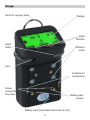
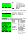
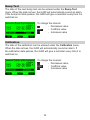
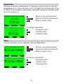
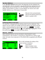
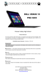
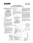
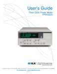
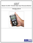
G450 Multi-gas Detector Operations Manual 1194 Oak Valley Dr, Ste 20, Ann Arbor MI 48108 USA (800) 959-0329 • (734) 769-0573 • www.goodforgas.com GfG Products for Increased Safety Congratulations on your purchase of a high technology product from GfG – you have made an excellent choice! Our detectors are characterized by reliability, safety, peak performance and economic efficiency. They comply with national and international directives. This manual will help you operate the detector quickly and safely. Please take note of these instructions before putting the device into operation! If you have any questions, please feel free to contact us. GfG Instrumentation, Inc. 1194 Oak Valley Drive, Ste 20 Ann Arbor, MI 48108 USA Phone: Fax: E-mail: Website: (800) 959-0329 or (734) 769-0573 (734) 769-1888 [email protected] www.goodforgas.com Table of Contents Introduction1 For Your Safety1 Application and Purpose 1 Design2 Operation3 Detection Mode3 Turning the Device Off 5 Display Illumination5 Individual Gas Display / Rotating the Display5 Battery 6 Alarms 6 Resetting Latching Alarms 7 STEL, TWA, Maximum / Minimum Values8 Peak – Adjusting Peak Values 8 Service Mode8 Main Menu 9 Location – Entering a Location 9 User – Entering User Name 10 Datalogger11 Datalogger(sample screen shots)12 Confidence Blip 13 ® AutoCal 14 Options14 Service Menu 14 System Menu 15 Bump Test 16 Calibration16 Inspection 17 Time 17 Options18 Latching Alarm Function 18 Sensor – Enable 18 ® AutoCal – Air 19 AutoCal® – Gas 19 Sensor Menu 19 Zeroing – Adjust Zero Point 20 Calibration21 Alarms – Adjust Alarm Thresholds22 Calibration Dates 22 Information23 CH4 Unit 23 Activate Lights 23 Replacing the Batteries and the Rechargeable Battery Pack Module23 Charging the Optional NiMH Battery Pack24 Cleaning24 Anti-lazy Battery Deep Discharge Cycle25 Maintenance and Inspection 26 Service – Repair 26 Accessories and Replacement Parts 27 Sensor Types and Detection Ranges . . . 28 Sensor Specifications 29 Technical Data 30 Caution31 Warranty 34 Introduction For Your Safety Like any piece of complex equipment, the GfG G450 will do the job it is designed to do only if it is used and serviced in accordance with the manufacturer’s instructions. CAUTION: For safety reasons, this equipment must be operated and serviced by qualified personnel only. Read and understand the instruction manual completely before operating or servicing this device. PRUDENCE:Pour des raisons de sécurité, cet équipement doit être utilisé et entretenu par du personnel qualifié. Lire et comprendre le manuel d’utilisation avant de faire fonctionner ou de réparer cet appareil. The warranties made by GfG with respect to the product are voided if the product is not used and serviced in accordance with the instructions in this manual. Please protect yourself and your employees by following them. The above does not alter statements regarding GfG’s warranties and conditions of sale and delivery. Application and Purpose The G450 is a handheld detector for personal protection from atmospheric hazards. The detector measures continuously in diffusion mode and gives visual and audible alarms if a gas-induced danger arises. The G450 meets the following approval: Classified as intrinsically safe for use in Class I, Division 1, Group A, B, C, and D Hazardous locations Temp code T3 Class I, Zone 0: Ex ia IIC T3 CSA C22.2 No. 152 ANSI / ISA-12.13.01-2000 UL 913 1 Design Hook for carrying strap Display Push Buttons Alarm LEDs Diffusion inlets Horn Contacts for accessories Screw connectors for pump Battery pack screws Battery pack (accessible from back of unit) 2 Operation GfG recommends frequent verification of accuracy. The safest course of action is to verify accuracy with a known concentration of gas prior to each day’s use. If the readings are less than 90% or greater than 120% (-10% to +20% accuracy) the detector must be calibrated before use. In compliance with c-CSA (Canada) the following requirements must be observed: CAUTION: Before each use, sensitivity must be tested on a known concentration of CO, H2S and combustible gas (depending on which sensors are installed) equivalent to 25 to 50% of the full scale concentration. Accuracy must be within -0 to +20% of the actual measurement. Accuracy may be corrected by performing an AutoCal® adjustment (see calibration). Detection Mode Turning the Device On Turn the G450 on in an environment known to be free from gases and / or vapors. Press the right key to turn the G450 on. After turning the G450 on, the display gives a short message about the detector, the user, the location (this message can be set in service mode). Should the date for the next inspection pass, the G450 gives an audible signal and the display reads “Inspection Overdue.” The display also shows every gas being measured, its detection range and the set alarm thresholds. 3 <no entry> <no entry> NOTE: GfG recommends that you “bump check” the sensors before each use to confirm their ability to respond to gas. To do this, expose the detector to a gas concentration that exceeds the alarm set points. Manually verify that the audible and visual alarms are activated. Calibrate if the readings are not within the specified limits. NOTE: GfG vous recommande de “test cogner” les capteurs avant chaque utilisation afin de confirmer leur capacité à répondre à gaz. Pour ce faire, exposer le détecteur à une concentration de gaz qui dépasse les points de consigne d’alarme. Vérifier manuellement que les alarmes sonores et visuelles sont activées. Calibrer si les lectures ne sont pas dans les limites spécifiées. 4 Turning the Device Off To turn the G450 off, hold the right key (ZOOM) for approximately 5 seconds. Display Illumination Whenever you press a key or any alarm condition is activated, the display illumination turns on. It turns off automatically after approximately 10 seconds, or when the alarm condition is corrected. Individual Gas Display / Rotating the Display The display can be rotated 180° by pressing the right and the left keys simultaneously. The G450 allows the user to store and display time-weighted averages (TWA), short-term exposure levels (STEL), peak values (MAX) and minimum values (MIN). The stored values have the following meanings: STEL: The STEL (short-term exposure level) is the average value of the gas concentration over a period of time, which is determined by the short-term period. Short-term exposure levels are used to evaluate exposure peaks. The short-term period is typically set to 15 minutes. TWA: The time-weighted average (TWA) is the average value of the gas concentration over an 8 hour working shift. For calculating the total dose, the G450 uses all gas levels measured since the detector was turned on. MIN / MAX: Minimum and peak values measured since the detector was switched on or since the stored values were reset. Press ZOOM briefly to view one gas at a time (ZOOM mode). Pressing ZOOM momentarily while in ZOOM mode will cycle to the next detected gas. 5 To read the stored values, press and hold the right key while in zoom mode. Press the key repeatedly to display all other measurement values and the battery capacity one after the other. Example – Zoom Display for H2S: Top left: Maximum value Top right: Actual gas concentration Bottom left: Short-term exposure level (STEL) Bottom right: Time-weighted average (TWA) Battery A fully charged G450 battery pack has a capacity of up to 25 hours of continuous operation in diffusion mode. The operational time may be reduced by sampling intervals or alarms. The remaining battery capacity is indicated by the battery symbol on the left side of the display. The black area represents the remaining capacity. When the capacity falls to 4% power save mode is displayed and the G450 gives both a visual (red alarm LED and an “discharged” battery symbol in the display) and an audible warning. Alarms If the measured gas concentration exceeds a pre-set threshold, the detector immediately gives audible, visual and vibrating alarms. The display also indicates the exceeded alarm threshold which caused the alarm. A loud acoustic alarm (103 dB at 30 cm), bright flashing LEDs and a vibrating alarm warn of dangerous gas concentrations. In case of a gas alarm the whole display turns orange or red, depending on the gas concentration and the exceeded alarm threshold. The G450 provides three instantaneous alarms for oxygen (O2) and combustible gases (CH4), and two alarms for toxic gases (CO, H2S). The G450 warns the user of dangerous conditions caused by oxygen deficiency or enrichment and levels of combustible and toxic gases which exceeds the alarm threshold. 6 For toxic gases there is an additional alarm for exceeded time-weighted averages and short-term exposure levels (TWA and STEL). Number of Alarms Alarm Type Sensors Instantaneous Value (AL) Oxygen Combustible gases Toxic gases 3 3 Short Term Value (STEL) Toxic gases 1 Long Term Value (TWA) Toxic gases 1 Over Range All 1 An instantaneous alarm is activated immediately if the gas concentration exceeds or falls below a pre-set threshold. The alarm values are adjustable. The short-term exposure limit (STEL) is the average concentration over a short period of time (e.g. 15 minutes). The STEL alarm is not latching; it resets automatically as soon as the concentration falls below the threshold. The time weighted average (TWA) refers to an 8-hour shift and calculates the average concentration. The TWA alarm cannot be reset. It is only deactivated if the detector is switched off. The screen will display Under Range All 1 The screen will display 2 Description Resetting Latching Alarms When alarm 2 and 3 are set to latching you must reset an activated alarm by pressing the RESET key. Alarm 1 will automatically reset when the gas danger has passed. If the detection range of the LEL sensor is exceeded, the display will read “ ”, indicating it is over range, instead of a value for gas concentrations above 110% LEL. To protect the sensor from damage, the device turns off the sensor. However, the audible and visual alarms and the “ ” message remain active. The alarms must be reset by pushing the RESET key. The display will read: “Fresh air?” If you have made sure that there is no combustible gas in the vicinity of the CH4 sensor, press yes to resume detection. 7 STEL, TWA, Maximum / Minimum Values When you turn the G450 on, the unit begins to measure continuously in diffusion mode. All concentrations are shown on the display. In addition, short term and long-term averages (STEL and TWA) are calculated for toxic gases; for non-toxic gases peak and minimum values (MAX and MIN) are stored. The stored values can be read from the display by accessing the applicable display mode. WARNING: To avoid possible personal injury, do not turn off the detector during a work shift. TWA, STEL and MAX readings are reset when the G450 is turned off. Peak – Adjusting Peak Values During peak mode (activated by pressing the left key PEAK), peak values can be monitored and displayed. The display shows an animated symbol in the bottom left corner. Within zoom display the peak value will be displayed instead of the gas concentration. Pressing RESET during peak mode will reset the peak memory to the current gas concentration. Pressing RESET during zoom display will reset the peak memory and the peak value memory to the current gas concentration. By pressing PEAK again peak mode is deactivated. Service Mode Hold the middle key (RESET) for approximately 5 seconds to activate service mode. In the service mode the program parameters of the G450 can be adjusted and changed. A menu highlights the different adjustment possibilities. Several menu points require an access code (1100) to prevent accidental modification of important functions. In service mode all alarms are deactivated. All adjustments in service mode are menu-controlled. The 3 keys stand for 8 the function which is shown in the bottom line of the display. The main menu is displayed first when you enter service mode. Main Menu The menu points are: 1.Location (the physical location of the G450) 2.User (user identity) 3.Datalogger (adjust datalogger function) 4.Alarm Clock (set alarm) 5.Service (start service menu) 6.AutoCal® 7.Options (adjust alarm volume and display contrast) The keys’ functions are explained in the bottom line of the display. In the main menu the keys have the following functions: Left key (↓↓scroll down) Middle key (SELECT) select menu point Right key (DETECT) back to detection mode Location – Entering a Location From a deposited table one location out of a hundred possible locations can be selected. The first two digits stand for the number of the table entry. With the exception of “00” all other 99 entries can only be edited with a PC. Within “00” up to 15 letters / figures can be entered, which will be stored as operational place in the G450. Entry is automatically completed when the cursor reaches the end mark (>). When Location is selected by the middle key (SELECT), the following is displayed, and the keys have the following functions: First a location number is specified: EDIT - Change location name ?no entry? EXIT - Back to main menu ↑↑ - Change location number 9 After selecting a location number (by pressing the right key – ↑↑) the location entry will be displayed. To change the location, press the left key (EDIT). The following is displayed, and the keys have the following functions: ABC↓ ↓ - Select symbol – move down EXIT - Enter the blinking letter for figure and move the cursor to the right no entry 012↑↑ - Select symbol - move up User – Entering User Name From a deposited table one entry out of ten possible entries can be selected. The first two digits stand for the number of the table entry. Except for “00,” the other 9 entries can only be edited with a PC. Within “00” up to 15 characters can be entered, which will be stored as “IDENTIFICATION” in the G450. Entry is automatically completed when the cursor reaches the end mark (>). The entry process for user name (ID) is the same as that of the location entry. EDIT - Change location name EXIT - Return to main menu ↑↑ - Change identification number ?no entry? 10 Datalogger Within the “datalogger” menu point different settings can be accessed: Full shows the used percentage of the datalogger memory ↓↓ - Jump to the next parameter ERASE- Deletes data. A security prompt will appear (clear data?) → confirm with yes (right key), deny with no (left key) EXIT - Back to main menu If Mode is selected, the instantaneous value (Instant), average value (Average) or peak value (Peak) can be chosen with the left or right key. If Interval is selected, the data recording interval can be set between 1 second and 60 minutes by pressing ↓↓ and ↑↑ 11 Datalogger (sample screen shots) 12 AutoCal® The AutoCal® menu point can be selected in the main menu or occurs automatically when the calibration adapter (Smart Cap) is connected. Within the AutoCal® menu point the device can be calibrated with fresh air (ZERO) or test gas (CAL). AIR - AutoCal® with fresh air GAS - AutoCal® with test gas EXIT - Back to main menu 13 Options Within Options you can adjust • Anti-Lazy battery • The buzzer volume (90 dB or 103 dB) • The screen contrast: 1 (very low) up to 15 (very high) ↓↓ - Scroll down CHANGE- Change selected parameter EXIT - Back to main menu NOTE: Rechargeable batteries inherently have a tendency to lose capacity over time. Some of this loss manifest itself as “voltage depression” (aka Lazy Battery). With GfG’s advanced battery management technology, some of the lost capacity can be restored using the “Anti-Lazy Battery” feature. The overall battery life can be extended if this feature is used at least once every three months. Confidence Blip Within the Confidence blip menu point, the interval between confidence blips can be chosen. The confidence blip can be heard in intervals of 15 to 90 seconds or be deactivated (- -). ↓↓ - Scroll down SELECT - Confirm interval EXIT - Return to main menu Service Menu Enter the service menu by selecting Service. Within the service menu the G450 program parameters can be adjusted. This menu point is only accessible with the code “1100.” The code prevents important functions from being changed by mistake or by unauthorized persons. In service mode all alarms are suppressed. 14 ABC↓↓ - <<>> - 012↑↑ - Previous digit Enter (cursor moves automatically to the next position). By holding the key the last entry will be deleted and the cursor will move one position back. Next digit After entering code “1100,” you enter the service menu (see System Menu) and can perform general adjustments (zeropoint, span, alarms, calibration, etc). Select Sensors to adjust sensor‑specific functions (alarms, calibration, etc). DETECT - Back to detection mode System Menu Within the System menu the following adjustments are possible: Bump Test - Date of next bump test Calibration - Date of next calibration Inspection - Date of next inspection Time - Date and time System Options - Change language, vibrating alarm, latch and auto save settings Sensor-Select - Turn sensors on or off AutoCal® - Air - Enable AutoCal® to zero specific sensors AutoCal® - Gas- Enable AutoCal® to adjust the sensitivity of specific sensors Information - Software version, instrument serial number, battery type, etc. 15 Bump Test The date of the next bump test can be entered under the Bump Test menu. When the date arrives, the G450 will automatically sound an alarm. If the bump test date passes, the G450 will give a reminder every time it is switched on. To change the interval: ↓↓ - Decreases value EXIT - Confirms value ↑↑ - Increases value Calibration The date of the calibration can be entered under the Calibration menu. When the date arrives, the G450 will automatically sound an alarm. If the calibration date passes, the G450 will give a reminder every time it is switched on. To change the inverval: ↓↓ - Decreases value EXIT - Confirms value ↑↑ - Increases value 16 Inspection The date of the next maintenance or inspection can be entered under the Inspection menu. When the date arrives, the G450 will automatically sound an alarm. If the inspection date passes, the G450 will give a reminder every time it is switched on. >> - Moves to the next parameter SELECT - Selects the blinking parameter EXIT - Back to system menu To change a parameter: ↓↓ - Decreases value EXIT - Confirms value ↑↑ - Increases value Time The time and date can be adjusted under the Time Menu. >> - Moves to the next parameter SELECT - Selects the blinking parameter EXIT - Back to system menu To change a parameter: ↓↓ - Decreases value EXIT - Confirms value ↑↑ - Increases value 17 System Options In the System Options menu point, the language can be changed, the vibrating alarm can be activated or deactivated and the latching and auto save features can be turned on or off. The length of time that the zoom display shows before it resets to normal display can also be set under System Options (e.g. 10S means 10 seconds). >> - Moves to the next parameter SELECT - Selects the blinking parameter EXIT - Back to system menu Latching Alarm Function The detector is shipped with the latching alarm function disabled. If the alarms are set to latch, the audible and visual alarms will persist until the alarm is acknowledged by pressing the center key (RESET). To enable latching alarms, press the left key (↓↓) until Latching is highlighted. Press the center key (On/Off) to enable latching alarms. Sensor – Select Each individual sensor can be activated or deactivated for each measurement. This function is necessary for applications in which a gas does not need to be measured or if the G450 will be upgraded with different sensors. ON or OFF indicates the status of the sensor (active or inactive). ↓↓ - Scroll down On/Off - Back to system menu Exit - Return to system Menu 18 AutoCal® – Air This menu point is to enable AutoCal® for sensors, using fresh air (zero calibration). Generally all sensors will be zero calibrated and show “ON.” ↓↓ - On/Off - Exit - Scroll down to next sensor Calibration/non-calibration of sensor in AutoCal® program Return to service Menu AutoCal® – Gas This menu point is to enable AutoCal® for sensors, using a test gas (gas calibration). Generally all sensors (except O2) will be calibrated and show ”ON.” ↓↓ - On/Off - Exit - Scroll down to next sensor Calibration/non-calibration of sensor in AutoCal® program Return to service Menu Sensor Menu The following functions refer to individual sensors in the G450. In the sensor menu each individual sensor can be selected. The adjustments are only valid for the selected sensor. For a description of sensor-specific adjustments, the O2 sensor is being used as an example. The adjustment options are the same for all sensors. ↓↓ - Move to next sensor SELECT - Select sensor Exit - Return to service Menu 19 For each sensor, the following adjustments can be made: Zero - Adjust the zero point Calibrate - Sensitivity calibration with test gas Alarms - Adjust alarm thresholds Calibration Dates - View the date and status of the last calibration and zero Information - View sensor information ↓↓ - Move to next menu point SELECT - Select menu point EXIT - Return to service menu Zeroing – Adjust Zero Point To adjust the zero point, the sensor menu point Zero must be selected. START - GAS - EXIT - Start zero point adjustment Enter zero gas concentration Back to “O2 menu” After entering GAS the display reads: ↓↓ - Zero gas value decreases by one unit EXIT - Enter Value ↑↑ - Zero gas value increased by one unit NOTE: To set the zero point for oxygen, supply the unit with 100% nitrogen through a calibration adapter. 20 Calibration During calibration, the sensitivity of the G450 is adjusted. Before starting calibration, make sure that the zero point adjustment has been done. For calibration you need a suitable test gas, e.g.: Detection Range Test Gas TOX Carbon monoxide (CO), hydrogen sulfide (H2S) Fresh air or test gas with 20.9% volume oxygen (O2) in OX nitrogen (N2) EX Methane (CH4) NOTE: Please call GfG for the correct calibration gas for your instrument. To adjust sensitivity, the sensor menu point Calibrate has to be selected. START - Start calibration GAS - Enter calibration gas concentration EXIT - Return to O2 Menu After entering GAS the display reads: ↓↓ - Decreases calibration gas value by one unit EXIT - Saves value ↑↑ - Increases calibration gas value by one unit 21 Alarms – Adjust Alarm Thresholds The G450 provides 3 alarm thresholds for each non-toxic gas (O2, CH4). For each toxic gas (H2S, CO) the G450 provides 2 alarm thresholds. The alarms are triggered when the gas concentration exceeds or falls below the threshold. For toxic gases an additional alarm for exceeded long-term and short-term averages can be set. After selecting the sensor menu point Alarms the following reading is displayed (here, for an O2 sensor): ↓↓ - Scroll down EDIT - Change alarm threshold EXIT - Back to O2 menu After selecting the alarm thresholds by pressing EDIT (e.g.: Alarm 1), the value can be entered: ↓↓ - Decreases alarm value by one unit EXIT - Back to Alarm menu ↑↑ - Increases alarm value by one unit WARNING: If alarm points are set to off (--), the user will not be notified of an alarm condition. This could result in injury or death. Calibration Dates Within the sensor menu point Calibration dates, the date of the last calibration can be displayed, as well as if the calibration was successful (√) or not (). 22 Information In this menu point, specific information for the sensor can be displayed: Type of sensor (ID) - Type of sensor Serial number (SN) - Serial number Detection range (NR) - Detection range Temperature range (TR) - Temperature range Operating time (OT) - Remaining sensor life CH4 Unit A unit equipped with a CH4 sensor has an additional Unit and gas menu point in which you can set the CH4 sensor to detect in % LEL or % volume along with a variety of combustible gases. Activate Lights The G450 provides an optional battery pack with lights. The lights can be switched on or off by holding down the left key for approximately 5 seconds. The lights are useful when the device is tied to a cord and lowered down into a sewer system. Using the lights can prevent the device from being dunked under water. Replacing the Batteries and the Rechargeable Battery Pack Module NOTE: Batteries must not be replaced in hazardous locations. Replace only in non‑hazardous locations. NOTE: Piles ne doivent pas être remplacés dans des endroits dangereux. Remplacez uniquement dans des endroits no dangereux. Turn the detector off before you replace the batteries. To replace the batteries or the supply module, unscrew the two screws on the front of the detector and pull the whole module backwards or insert the allen wrench through one of the screw holes to push the module backwards. When the alkaline batteries have to be replaced, use a thin object to push the two battery cells out through the PCB holes. When inserting new batteries, check for the correct polarity (see plastic holder). Secure the supply module by replacing the two screws. NOTE: Failure to use Duracell AA MN1500 LR6 batteries will void the warranty. NOTE: Utilisez uniquement des piles AA, Duracell MN 1500 LR6. 23 Charging the Optional NiMH Battery Pack WARNING: The detector must not be charged in a hazardous location. Only charge in non-hazardous atmospheres of 4 to 122°F (-20 to 50°C). Charge the detector using only the recommended charging adapter. Do not use any other charging adapter, as a fire or an explosion may result. Do not connect the charging adapter to voltages other than those used in North America, or an explosion may result. The rechargeable G450 battery pack module can be charged with the GfG Drop-in Charger. The Drop-in Charger is also available as a vehicle charging unit. Make sure the maximum connected voltage does not exceed 30 V. To charge the G450, simply slide the device into the charging unit. The G450 will beep and then display either “quick charge” or “trickle-charge.” These two modes indicate the charge status of the G450. When the rechargeable battery pack is completely depleted, it will take approximately 6 hours to recharge in quick-charge mode. Then the Drop-in Charger will automatically switch to trickle‑charge mode so that it is impossible to overcharge the battery pack. Both charging modes are indicated on the G450’s display. When the charger changes to trickle-charge mode, the battery pack has reached at least 80% of its capacity. An additional 2-3 hours of trickle-charge will fully charge the detector. The G450 will keep charging as long as it is plugged into the charger. Charging can be stopped by removing the G450 from the Drop-in Charger or by unplugging the charger. Cleaning The casing can be cleaned with a damp cloth. Never use solvents or detergents! 24 Anti-lazy Battery Deep Discharge Cycle NiMH batteries can develop voltage depression. Even though the normal amount of power is stored in the battery, the peak voltage in “lazy” batteries drops more quickly than usual. To the user it appears the battery is not holding its full charge. Fully charged instruments that fail to operate for the expected time should be exercised by means of the “anti-lazy battery” deep discharge cycle. G450 instruments with version 3.41 and higher firmware have the enhanced “anti-lazy battery” feature. GfG recommends updating your instrument firmware and updating to the latest version charger cradle and power adapter to take full advantage of the latest “anti-lazy battery” options. The latest version has a blue case and the serial number ends with a “D”. Contact an authorized GfG service center or distributor for assistance. The “anti-lazy battery” procedure is initiated by following these steps: 1. Press and hold the “Reset” button until “Main menu” choices appear 2. Select “Options”, you will need to arrow down the list to select it 3. From the “Options menu” choose “Anti-Lazy-Batt.” 4. Press “Change” to turn on the one-time deep discharge feature 5. Display will show “1X” instead of “Off” to the right 6. Press “Exit” then “Detect” to return the instrument to normal operation NOTE: Do not turn the instrument off! 7. Allow it to run until the battery is completely drained, then recharge as normal If you have the latest version of firmware on the instrument and the latest version charger cradle and power adapter, when the battery icon shows it is down to the last 10% remaining voltage the instrument can be placed in the charger and the instrument will complete the anti-lazy battery deep discharge, then charge normally. NOTE: The instrument needs to be programmed for automatic activation. To set the instrument for automatic activation, follow steps 1 through 4 above, then follow these steps: 5. Choose “Days” 6. Select “Anti-Lazy days”, you will need to arrow down the list to select it 7. Press “Change” 8. Select the desired days for the automatic activation of this feature 9. Select “Exit” twice then “Detect” to return the instrument to normal operation 25 Maintenance and Inspection Maintenance includes service, calibration and adjustment, as well as repair if it is necessary. Gas monitoring devices can react differently depending on environmental conditions. It is important, independent from maintenance duties, to test the device before putting it into operation each day. Bump testing before each use is highly recommended. Service – Repair WARNING: To avoid personal injury or damage to the detector, use only the specified replacement parts. CAUTION: When using the optional motorized pump, block the pump inlet to test low flow alarm prior to each use. The low flow alarm must activate when air flow is compromised. A function test must be executed before the first operation and at least once a year. This test comprises (depending on use and sensor exposure to poisons and contamination): • Check zero point • Charge battery (optional) • When using optional pump, consult the G400 MP-2 pump operations manual for warnings and proper instructions. • Test sensors with standard test gas (bump test) and adjust, if necessary • Check alarm signals • Test response time NOTE: GfG recommends that you “bump check” the sensors before each use to confirm their ability to respond to gas. To do this, expose the detector to a gas concentration that exceeds the alarm set points. Manually verify that the audible and visual alarms are activated. Calibrate if the readings are not within the specified limits. NOTE: GfG vous recommande de “test cogner” les capteurs avant chaque utilisation afin de confirmer leur capacité à répondre à gaz. Pour ce faire, exposer le détecteur à une concentration de gaz qui dépasse les points de consigne d’alarme. Vérifier manuellement que les alarmes sonores et visuelles sont activées. Calibrer si les lectures ne sont pas dans les limites spécifiées. Any G450 repair must be done according to the manufacturer’s instructions and with genuine spare parts. Return to GfG for proper service. 26 Accessories and Replacement Parts Part Number Aspirator, hand (with wand) 7711-450 Batteries, alkaline (AA) 4002-001 Battery hardware kit (includes 6 screws and hex key) 4003-450 Charger, gang / 2-unit 1450-200 Battery pack, alkaline (without batteries) with vibrator 1450-202 Battery pack, rechargeable NiMH with vibrator 1450-211 Battery pack, rechargeable NiMH with vibrator and lights 1450-212 Cable, data downloading / USB interface (for PC) 1650231 Calibration adapter with tubing 7771-450 Calibration connector 1450225 Charger, plug-in (110 VAC) wall pack 4001-650 (for use with drop‑in charger) Charger, vehicle 4001-650V Crocodile clip (includes screw) 943950 Datalogging kit – alkaline 1450235 (cable, software and drop-in cradle charger) Datalogging kit – rechargeable (cable and software) 1450235R Drop-in cradle charger (charge and data transfer) (single) 1450220 Drop-in cradle charger (charge and data transfer) (double) 1450220D Regulator, (for aluminum calibration gas cylinders) 2603-025 0.5 lpm fixed flow rate with pressure gauge and on / off knob Regulator, (for steel calibration gas cylinders) 2603-020 0.5 lpm fixed flow rate with pressure gauge and on / off knob Sensor - carbon monoxide, (CO) 0 - 500 ppm 1450004 Sensor - carbon monoxide, (CO-H) 0 - 500 ppm 1450014 reduced H2 sensitivity Sensor - hydrogen sulfide, (H2S) 0 - 100 ppm 1450003 Sensor - methane, (CH4) 0 - 100 %LEL 1450005 (combustible gases) Sensor - oxygen, (O2) 0 - 25% volume 1450001 Software, datalogging (CD only) 1450233 Spare parts and accessories should be stored at ambient temperatures of 32 to 86°F (0 to 30°C). Storage time should not be longer than 5 years. Electrochemical sensors should not be stored for more than 6 months. When you store oxygen sensors, be aware that storage reduces the expected lifetime of the sensor. When storing spare sensors, make sure that the ambient atmosphere is free from corrosive substances and sensor poisons. 27 Sensor Types and Detection Ranges Warning: To avoid personal injury, use only sensors specifically designed for this detector. Plug Sensor Part Detection Range Number EC1 1450003 0-100 ppm EC2 1450004 0-500 ppm EC2 1450014 0-500 ppm EC3 1450001 0-25% volume PL 1450005 0-100% LEL * T-Band = Tolerance band Gas Resolution T-Band* Hydrogen sulfide (H2S) Carbon monoxide (CO) Carbon monoxide (CO-H) Oxygen (O2) Methane (CH4) 0.1 ppm 1 ppm 1 ppm 0.1% volume 0.5 %LEL ±0.2 ppm ±3 ppm ±3 ppm ±0.2% volume ±2.5 %LEL 28 Sensor Specifications MK221 Catalytic combustion sensor for combustible gases and vapors (GfG part number 1450005) Response time: t50: <10 seconds t90: <30 seconds Pressure: 950 to 1,100 hPa: Maximum ±5% of detection range or ±15% of display (1,013 hPa) Humidity: 5% to 90% r.h.: Maximum ±5% of detection range or ±15% of display (55% r.h.) -4 to 122°F Temperature: Maximum ±3% of detection range or ±10% of display (68°F or 20°C) (-20 to +50°C): Expected lifetime: 3 years MK429 Electrochemical sensor for hydrogen sulfide H2S (GfG part number 1450003) Response time: t20: <5 seconds t90: <45 seconds Pressure: 800 to 1,200 hPa: Maximum ±3 ppm or ±10% of display (1,000 hPa) Humidity: 20% to 90% r.h.: Maximum ±3 ppm or ±10% of display (50% r.h.) -40 to 122°F Temperature: Maximum ±3 ppm or ±20% of display (68°F or 20°C) (-40 to +50°C): Cross sensitivity: SO2: 20% , NO2: 35% , NO: <2% , CO: <0.5% , H2 <0.1% (*1) Expected lifetime: 3 years MK369 Electrochemical sensor for carbon monoxide CO (GfG part number 1450002) Response time: <45 seconds (<90 seconds without diffusion acceleration) Pressure: 800 to 1,200 hPa: Maximum ±3 ppm or ±10% of display (1,000 hPa) Humidity: 15% to 90% r.h.: Maximum ±3 ppm or ±10% of display (50% r.h.) -4 to 122°F Temperature: Maximum ±3 ppm or ±15% of display (68°F or 20°C) (-20 to +50°C): Cross sensitivity: H2: <10% , NO: <9% , H2S: 0% , SO2: 0% (*1) Expected lifetime: 3 years MK376 Electrochemical sensor for oxygen O2 (GfG part number 1450001) Response time: t20: <5 seconds t90: <10 seconds Pressure: 800 to 1,200 hPa: Maximum ±0.2% volume or ±2.5% of display (1,000 hPa) Humidity: 10% to 90% r.h.: Maximum ±0.2% volume or ±2.5% of detection range (50% r.h.) Temperature: -4 to 122°F Maximum ±0.5% volume or ±2.5% of display (68°F or 20°C) (-20 to +50°C): Expected lifetime: 3 years (*1) Displayed value with reference to the supplied gas concentration 29 Technical Data Type: Detection principle: Detection range: Response time t90: Expected sensor life: Gas supply: Display: Alarm: Climate conditions: for operation: for storage: Zero point and sensitivity calibration: Operational time: Power supply: G450 Electrochemical (EC): toxic gases and oxygen Catalytic combustion (CC): combustible gases and vapors (up to 100% LEL) See Sensor Type and Detection Range See Sensor Specifications 3 years Diffusion Illuminated full-graphic LCD, automatic size adjustment for optimal read out, battery capacity display, gas concentration as instantaneous and peak value Depending on gas type; 2 or 3 instantaneous and 2 dosimeter alarms, low battery alarm Visual and audible warning and display indication, coloring of display depending on alarm status (orange/red) Buzzer: 103 dB (can be restricted to 90 dB) -4 to 122°F (-20 to +50°C) / 5 to 95% r. F. / 70 to 130 kPa -13 to 122°F (-25 to +50°C) / 5 to 95% r. F. / 70 to 130 kPa (recommended 32 to 86°F (0 to +30°C) Manual or automatic with calibration program Up to 25 hours 1. NiMH battery module, rechargeable Im=1 A (maximum charging current) Um=30 VDC (maximum voltage) or 2. Alkaline battery module, non-rechargeable with 2x size AA Duracell MN1500 LR6 Casing: Material: Dimensions: Weight: Protection: Approvals: CSA Approval: Rubberized plastic 2.95x4.33x2.17 inches (75x110x55 mm) (HxWxD) 10.23 oz. (290 g) IP 67 cCSAus Class I, Division 1, Group A, B, C and D Hazardous locations Temp code T3 Class I, Zone 0: Ex ia IIC T3 CSA C22.2 No. 152 ANSI / ISA-12.13.01-2000 30 Prudence: ¾¾ Never substitute any components as this may compromise the G450s intrinsic safety. ¾¾ Ne jamais remplacer les composants, car cela pourrait compromettre la sécurité intrinsèque du G450. ¾¾ For safety reasons, this equipment must be operated and serviced by qualified personnel only. Read and understand the user manual completely before operating or servicing this device. ¾¾ Pour des raisons de sécurité, cet équipement doit être utilisé et entretenu par du personnel qualifié. Lire et comprendre le manuel d’utilisation avant de faire fonctionner ou de réparer cet appareil. ¾¾ Do not use the detector if it is damaged. Before you use the detector, inspect the case. Look for cracks or missing parts. ¾¾ Ne pas utiliser le détecteur s’il est endommagé. Avant d’utiliser le détecteur, inspectez le cas de fissures ou de pièces manquantes. ¾¾ If the detector is damaged or something is missing, contact GfG Instrumentation, Inc. immediately. ¾¾ Si le détecteur est endommagé ou qu’il manque quelque chose, contactez GfG Instrumentation Inc. immédiatement. ¾¾ Calibrate the detector before first-time use and then on a regular schedule, depending on use and sensor exposure to poisons and contaminants. ¾¾ étalonner le détecteur avant la première utilisation, puis à intervalles réguliers, en fonction de l’utilisation et de l’exposition du capteur aux poisons et des contaminants. ¾¾ GfG recommends that you “bump test” the sensors before each use to confirm their ability to respond to gas. To do this, expose the detector to a gas concentration that exceeds the alarm set points. Manually verify that the audible and visual alarms are activated. Calibrate if the readings are not within the specified limits. ¾¾ GfG vous recommande de “test cogner” les capteurs avant chaque utilisation afin de confirmer leur capacité à répondre à gaz. Pour ce faire, exposer le détecteur à une concentration de gaz qui dépasse les points de consigne d’alarme. Vérifier manuellement que les alarmes sonores et visuelles sont activées. Calibrer si les lectures ne sont pas dans les limites spécifiées. 31 ¾¾ It is recommended that the combustible sensor be checked with a known concentration of calibration gas after any known exposure to catalyst contaminants/poisons (sulfur compounds, silicon vapors, halogenated compounds, etc). ¾¾ Il est recommandé que le capteur de gaz inflammables être vérifié avec une concentration connue de gaz d’étalonnage après une exposition connue à catalyseur contaminants / poisons (composés soufrés, des vapeurs de silicium, composés halogénés, etc) ¾¾ The combustible sensor is factory calibrated to 50% LEL methane. If monitoring a different combustible gas in the % LEL range, calibrate the sensor using the appropriate gas. ¾¾ Le capteur de gaz combustible est calibré en usine à 50% LIE méthane. Si le suivi d’un autre gaz combustible dans la gamme de% LEL, étalonner le capteur en utilisant le gaz approprié. ¾¾ High off-scale readings may indicate an explosive concentration. ¾¾ Haute lectures hors échelle peut indiquer une concentration explosive. ¾¾ Only the combustible gas detection portion of this instrument has been assessed for performance by CSA International. ¾¾ Seule la partie de détection de gaz combustible de cet instrument a été évaluée pour la performance par CSA International. ¾¾ Protect the combustible sensor from exposure to lead compounds, silicones and chlorinated hydrocarbons. Although certain organic vapors (such as leaded gasoline and halogenated hydrocarbons) may temporarily inhibit sensor performance, in most cases the sensor will recover after calibration. ¾¾ Protégez le capteur de gaz combustible à partir de l’exposition au plomb, composés silicones et des hydrocarbures chlorés. Bien que certaines vapeurs organiques (comme l’essence au plomb et les hydrocarbures halogénés) peuvent inhiber temporairement les performances du capteur, dans la plupart des cas, le capteur va récupérer après calibration. ¾¾ For use only in hazardous locations where oxygen concentrations do not exceed 20.9% volume (v/v). ¾¾ A utiliser uniquement dans des endroits dangereux où les concentrations d’oxygène ne dépasse pas 20,9% en volume (v / v). 32 ¾¾ Any rapidly increasing reading followed by a declining or erratic reading may indicate a gas concentration beyond the upper scale limit, which may be hazardous. ¾¾ Toute lecture augmente rapidement suivie par une lecture diminution ou irrégulière peut indiquer une concentration de gaz au-delà de la limite supérieure de l’échelle, ce qui peut être dangereux. ¾¾ Extended exposure of the G450 to certain concentrations of combustible gases and air may stress detector elements, which can seriously affect the device’s performance. If an alarm occurs due to a high concentration of combustible gases, recalibration should be performed, or if needed, the sensor replaced. ¾¾ Une exposition prolongée de la G460 à certaines concentrations de gaz combustibles et d’air peut souligner éléments détecteurs, qui peuvent sérieusement affecter les performances de l’appareil. Si une alarme se produit en raison d’une forte concentration en gaz combustibles, l’étalonnage doit être effectué, ou en cas de besoin, le capteur remplacé. ¾¾ Do not test the combustible sensor’s response with a butane cigarette lighter; doing so can damage the sensor. ¾¾ Ne pas tester la réponse des capteurs combustible avec un briquet au butane, cela peut endommager le capteur. ¾¾ Do not expose the detector to electrical shock and/or severe continuous mechanical shock. ¾¾ Ne pas exposer le détecteur de choc électrique et / ou sévère choc mécanique continue. ¾¾ Do not attempt to disassemble, adjust or service the detector unless instructions for that procedure are contained in the manual and/or that part is listed as a replacement part. ¾¾ N’essayez pas de démonter, modifier ou réparer le détecteur à moins que des instructions pour que la procédure se trouvent dans le manuel et / ou la partie est répertorié comme une pièce de rechange. ¾¾ Electromagnetic interference (EMI) signals may cause incorrect operation of this detector. ¾¾ interférence des signaux électromagnétiques (EMI) peut entraîner un mauvais fonctionnement de ce détecteur. 33 Warranty GfG Instrumentation warrants our products to be free from defects in material and workmanship when used for their intended purpose, and agrees to remedy any such defect or to furnish a new part (at the option of GfG Instrumentation) in exchange for any part of any product that we manufacture that under normal use is found to be defective; provided that the product is returned, by the purchaser, to GfG’s factory, intact, for our examination, with all transportation costs prepaid, and provided that such examination reveals, in our judgment, that it is defective. This warranty does not extend to any products that have been subjected to misuse, neglect, accident, or unauthorized modifications; nor does it extend to products used contrary to the instructions furnished by us or to products that have been repaired or altered outside of our factory. No agent or reseller of GfG Instrumentation may alter the above statements. 34 Notes: _____________________________________________________________ _____________________________________________________________ _____________________________________________________________ _____________________________________________________________ _____________________________________________________________ _____________________________________________________________ _____________________________________________________________ _____________________________________________________________ _____________________________________________________________ _____________________________________________________________ _____________________________________________________________ _____________________________________________________________ _____________________________________________________________ _____________________________________________________________ _____________________________________________________________ _____________________________________________________________ _____________________________________________________________ _____________________________________________________________ _____________________________________________________________ _____________________________________________________________ _____________________________________________________________ _____________________________________________________________ _____________________________________________________________ _____________________________________________________________ _____________________________________________________________ _____________________________________________________________ _____________________________________________________________ _____________________________________________________________ _____________________________________________________________ _____________________________________________________________ _____________________________________________________________ _____________________________________________________________ _____________________________________________________________ _____________________________________________________________ _____________________________________________________________ _____________________________________________________________ GfG reserves the right to change part numbers, prices and/or technical information without notice. All rights reserved to correct typographical errors. 1194 Oak Valley Drive, Suite 20 Ann Arbor, MI 48108 US/Canada: (800) 959-0329 Fax: (734) 769-1888 35 This page intentially left blank. 36 GfG Instrumentation, Inc. 1194 Oak Valley Dr. Suite 20 Ann Arbor, MI 48108 USA US/Canada: US/Canada Fax: International: International Fax: Website: (800) 959-0329 (734) 769-1888 +1 734 769 0573 +1 734 769 1888 www.goodforgas.com Worldwide Manufacturer of Gas Detection Solutions 2015 7004-450 Rev 14 (11/11/15)