1
Function Generator
Model : GFG-3015
Operation Manual
82FG-30150MB
i
Table of Contents
Page
1. Precautions......................................................................................................................... 2
2. Product Introduction.......................................................................................................... 5
3. Features .............................................................................................................................. 6
4. Specifications ..................................................................................................................... 7
5. Front and Rear Panels ..................................................................................................... 10
6. Operation .......................................................................................................................... 18
6.1 The First Step Setup For Instrument .................................................................... 18
6.2 The Setup of Output Function............................................................................... 18
6.3 The Setup of Frequency......................................................................................... 18
6.4 The Setup of Amplitude ......................................................................................... 19
6.5 The Setup of Offset ................................................................................................ 19
6.6 The Setup of Duty................................................................................................... 20
6.7 The Setting of STORE ............................................................................................ 20
6.8 The Setting of RECALL .......................................................................................... 20
6.9 The SHIFT Key and Function Keys ....................................................................... 21
6.10 Setup of LIN or LOG Sweep................................................................................. 21
6.11 Setup of AM Modulation ...................................................................................... 25
6.12 Setup of FM Modulation....................................................................................... 26
6.13 Setup of Trigger.................................................................................................... 28
6.14 Setup of GATE and BURST ................................................................................. 30
6.15 Setup of External Counter ................................................................................... 32
6.16 THE VCF Function ................................................................................................ 34
6.17 THE GCV Output Function................................................................................... 35
6.18 THE TTL Signal Output Function ........................................................................ 36
6.19 THE SYNC Signal Output Function..................................................................... 36
6.20 Remote Control - RS232 Interface ...................................................................... 36
6.21 Commands Syntax ............................................................................................... 38
6.22 The Commands of RS-232 Serial Interface ........................................................ 41
6.23 The Examples of the Communication Interface Software ................................ 44
6.24 The Error message of instrument ....................................................................... 47
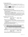
7. Adjustment and Correction ............................................................................................. 48
7.1 Preparation.............................................................................................................. 48
7.2 Adjust and Check up the operation DC Voltage.................................................. 48
7.3 Adjusting Main Clock ............................................................................................. 49
7.4 Adjusting Sensitivity of counter ........................................................................... 49
7.5 Adjusting VCF Function 100:1 .............................................................................. 49
7.6 Adjusting Main Frequency , Duty Cycle and GCV Output Check ...................... 49
7.7 Adjusting Rise/Fall Time........................................................................................ 50
7.8 Adjusting Main Sine wave Harmonic Distortion.................................................. 50
7.9 Adjusting Modulation source ................................................................................ 50
7.9.1 Adjusting Rate and symmetry............................................................................ 50
7.9.2 Adjusting Sine wave Harmonic Distortion ........................................................ 51
7.10 Adjusting AM modulation .................................................................................... 51
7.11 Adjusting FM and Sweep Function..................................................................... 53
7.12 Adjusting Trigger Phase ...................................................................................... 55
7.13 Calibrating by Software ....................................................................................... 56
8. The Block Diagram and Description of the System ...................................................... 62
ii
EC Declaration of Conformity
We
GOOD WILL INSTRUMENT CO., LTD.
No. 7-1, Jhongsing Rd, Tucheng City,Taipei County 236, Taiwan
GOOD WILL INSTRUMENT (SUZHOU) CO., LTD.
No. 69, Lushan Road, Suzhou New District Jiangsu, China
declares that the below mentioned product
GFG-3015
is herewith confirmed to comply with the requirements set out in the Council Directive on the
Approximation of the Law of Member States relating to Electromagnetic Compatibility (89/336/EEC,
92/31/EEC, 93/68/EEC) and Low Voltage Equipment Directive (73/23/EEC, 93/68/EEC). For the
evaluation regarding the Electromagnetic Compatibility and Low Voltage Equipment Directive, the
following standards were applied:
◎ EMC
EN 61326-1: Electrical equipment for measurement, control and laboratory use –– EMC
requirements (1997+A1: 1998+A2: 2001)
Conducted and Radiated Emissions
Electrostatic Discharge
EN 55011: 1998 class A
EN 61000-4-2: 1995+A1:1998
Current Harmonic
Radiated Immunity
EN 61000-3-2: 2000
EN 61000-4-3: 1996+A1:1998
Voltage Fluctuation
Electrical Fast Transients
EN 61000-3-3: 1995
EN 61000-4-4: 1995
Surge Immunity
------------------------EN 61000-4-5: 1995
Conducted Susceptibility
------------------------EN 61000-4-6: 1996
Power Frequency Magnetic Field
------------------------EN 61000-4-8 : 1993
Voltage Dips/ Interrupts
------------------------EN 61000-4-11: 1994
◎ Safety
Low Voltage Equipment Directive 73/23/EEC & amended by 93/68/EEC
Safety Requirements
IEC/EN 61010-1: 2001
GFG-3015
p.1
1. Precautions
GFG-3015 is specially designed for safety operation. It has passed through
rigorous tests of inclement environment to ensure its reliability and good condition.
The following precautions are recommended to insure your safety and keep the
best condition of the equipment.
(1) Safety Terms and Symbols
The following terms and symbols may appear in this manual:
!
!
This statement identifies conditions or practices that could
result in injury or loss of life.
This statement identifies conditions or practices that could
CAUTION
result in damage to this product or other properties.
WARNING
The following terms and symbols may appear on the product:
This term indicates an immediately accessible injury hazard.
DANGER
This term indicates that an injury hazard may occur, but is
WARNING
not immediately accessible.
This term indicates potential damage to this product or other
CAUTION
properties.
!
DANGER
High voltage
Protective
Conductor
Terminal
ATTENTION
refer to manual
Double
Insulated
DANGER
Hot surface
Earth
Ground
Terminal
(2) Do not place any heavy objects on the instrument under any circumstances.
(3) Disassembling the instrument
Due to the precision of this instrument, all the procedures of disassembling,
adjusting, and maintenance should be performed by a professional technician. If
the instrument has to be opened or adjusted under some unavoidable conditions,
and to be managed by a technician who is familiar with GFG-3015. Once there is
any abnormality, please contact our company or our distributor near you.
(4) Power Supply
AC input should be within the range of line voltage±15%, 50/60Hz. To prevent the
instrument from burning up, be sure to check the line voltage before turning on
power.
p. 2
GFG-3015
(5) Grounding
!
WARNING
To avoid electrical shock, the power cord protective grounding
conductor must be connected to ground.
GFG-3015 can be operated only with an earth grounded AC power cord that
connects the case and ground well. This is to protect the user and the instrument
from the risk of shock hazard.
(6) Fuse Replacement
!
WARNING
For continued fire protection, replace fuse only with the
specific type and rating by qualified personnel. Disconnect the
power cord before replacing fuse.
The fuse blows only when there is any wrong on the instrument, which will stop
working under this situation. Please find out the cause, then open the outside case
(Please see the Figure (A), Figure (B) on below) and replace a proper fuse as
listed below. Be sure to use the correct fuse before changing the applying location.
F101
: T 0.8A/250V
F100
: T 0.5A/250V
Check the line voltage setting on the rear panel. If the line voltage setting does not
match, Please change the line voltage setting according to the following steps:
1. Remove line cord from AC socket.
2. Switch the “AC line voltage switch” to correct setting with flat-blade
screwdriver and reinsert.
Figure (A)
Figure (B)
(7) Cleaning the Cabinet
Disconnect the AC power cord before cleaning the instrument.
Use a soft cloth dampened in a solution of mild detergent and water. Do not spray
cleaner directly onto the instrument, since it may leak into the cabinet and cause
damage.
Do not use chemicals containing benzing, benzne, toluene, xylene, acetone, or
similar solvents.
GFG-3015
p.3
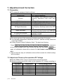
(8) Operation environment
Indoor use
Altitude up to 2000m
Temperature to satisfy the specification :
Operating temperature :
Storage temperature :
Relative humidity :
Installation category:
Pollution degree:
CAT Ⅳ
CAT Ⅲ
CAT Ⅱ
CAT Ⅰ
18oC ~ 28oC (+64.4oF ~ +82.4oF)
0oC ~ 40oC (+32oF ~ +104oF)
-10oC ~ 70oC (+14oF ~ 158oF)
up to 90% when 0oC~35oC;
up to 70% when 35oC~40oC
CAT Ⅱ(The detail is as Table A)
2
Table A
For measurements performed at the source of the lowvoltage installation.
For measurements performed in the building installation.
For measurements performed on circuits directly
connected to the low-voltage installation.
For measurements performed on circuits not directly
connected to Mains.
(9) Place GFG-3015 in a location with a suitable environment as stated above free
from dust, direct exposition of sunlight, and strong effect of magnetic fields.
(10) For United Kingdom
As the colours of the wires in mains leads may not correspond with the
coloured markings identified in your plug/appliance, proceed as follows:
NOTE
This lead/appliance must only be
wired by competent persons.
The wire which is coloured Green and Yellow must be connected to the
Earth terminal marked with the letter E or by the earth symbol
or
coloured Green or Green and Yellow.
The wire which is coloured Blue must be connected to the terminal which
WARNING
THIS APPLIANCE MUST BE
EARTHED
is marked with the letter N or coloured Blue or Black.
The wire which is coloured Brown must be connected to the terminal
marked with the letter L or P or coloured Brown or Red.
If in doubt, consult the instructions provided with the equipment or contact
IMPORTANT
The wires in this lead are
coloured in accordance with the
following codes:
the supplier.
This cable/appliance should be protected by a suitably rated and
approved HBC mains fuse; refer to the rating information on the
equipment and/or user instructions for details.
As a guide, cable of
0.75mm2 should be protected by a 3A or 5A fuse. Larger conductors
Green/Yellow :Earth
Blue
:Neutral
:Live
Brown
(Phase)
would normally require 13A types, depending on the connection method
used.
Any moulded mains connector that requires removal/replacement must be
destroyed by removal of any fuse and fuse carrier and disposed of
immediately, as a plug with bared wires is hazardous if engaged in a live
socket. Any re-wiring must be carried out in accordance with the
information detailed in this section.
p. 4
GFG-3015
2. Product Introduction
The frequency feedback method applied by GFG-3015 is a new technique that
generates stable output frequency with extraordinary accuracy for Function
Generator.
The traditional function generators typically use integrating circuit and constant
current circuit techniques that are easily affected by operation temperature or the
quality of resistor or capacitor and other key components to occur poor frequency
accuracy. The innovative design for GFG-3015 is to get rid of these problems.
The frequency feedback system needs a compatible, powerful frequency counter.
GW has designed his own full-function counter chip, GFC-9701, for this system with
high frequency test range and full functions, including Period test, Duty test, Ratio test,
Time interval, Pulse wide, direct display and direct connect with CPU system.
GFG-3015 uses this Chip to read output frequency value at any time. Then CPU
will modify the correct value of D/A converter immediately according to this value, so
that the user can get a high accuracy frequency from GFG-3015 Function Generator.
Besides, the GFG-3015 can also generate a high accuracy frequency to provide
high frequency resolution.
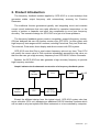
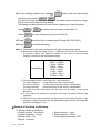
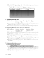
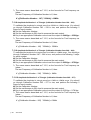
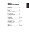
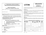
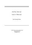
Graph1 indicates the fundamental construction of a frequency feedback system.
D/A
Convertor
User
Interface
CPU
VCO
AMP
O/P
Counter
(GFC-9701)
Except the different design from the typical circuit, GFG-3015 system also has
micro controller (CPU unit) equipping an additional RS-232 interface functions which
will be used on any test system with other instrument or to be controlled by computer.
GFG-3015
p.5
3. Features
GFG-3015 is a functional Function generator that applies Frequency feedback
control system technique and can generate high frequency accuracy with high
resolution. Its main signal source can generate waveforms including sine wave,
square wave, triangle wave, and ramp wave.
There are additional features listed as follows:
All digitized operation user interface
Output Waveforms of Sine, Square, Triangle, Ramp, Pulse, AM, FM, Sweep,
Trigger and Gate or Burst.
Wide output frequency range 0.01Hz ~ 15MHz.
High frequency accuracy 0.02% ± 5 count.
Maximum frequency resolution 10mHz.
Dual displays indicate frequency and amplitude or other necessary information.
Built-in 6-digit INT/EXT Function Counter and up to 150MHz frequency range with
high resolution.
INT/EXT AM/FM Modulation with internal modulation signal output.
LIN/LOG Sweep Mode with internal sweep signal output.
VCF of 100:1 EXT Frequency Control.
SYNC Output.
TTL Output.
Synchronization GCV Output.
Variable DC Offset Control
Output Overload Protection
RS232 Interface Standard
p. 6
GFG-3015
4. Specifications
Output Waveforms
Sine, Square, Triangle, ± Ramp, Pulse, AM, FM, Sweep,
Trigger, Gate or Burst
Frequency Range 10mHz~15MHz in 8 Frequency Range (auto switch)
Frequency
Resolution
1.5001MHz ~ 15.0000MHz …(100Hz)
150.01kHz ~ 1.50000MHz…(10Hz)
15.001kHz ~ 150.000kHz…(1Hz)
1.5001kHz ~ 15.0000kHz…(0.1Hz);
150.01Hz ~ 1.50000kHz…(10mHz)
15.01Hz ~ 150.00Hz…(10mHz)
1.51Hz ~ 15.00Hz…(10mHz)
0.01Hz ~ 1.50Hz…(10mHz)
Frequency
Accuracy
0.02% ±5 Count
Output Impedance 50Ω ± 10%
Range
10.00V~0.01V (into 50Ω) 4 amplitude
ranges
| Vac peak | + | Vdc | < 5V
Amplitude
Resolution
Accuracy
Unit
Range
DC Offset
Resolution
Accuracy
Control Range
Duty
Resolution
Accuracy
Sync Output
Sine
Square
Impedance
Level
Distortion
Asymmetry
Rise or Fall Time
Triangle and Ramp
Linearity Error
10mV(10.00V~0.01V)
≤3% ±5count at 10Hz~1MHz
≤10% ±5count at 1MHz~15MHz
Vpp, Vrms, dBm
± 5V (into 50Ω)
| Vac peak | + | Vdc | < 5V
10mV
≤3% ±3count at Amplitude Min.
80%:20%:80% to 1MHz
1%
≤1% to 1MHz at 50% Duty
50 Ω ±10%
>1Vp-p open circuit
≤0.5%(-46dBc) From 10Hz~100kHz
≤-30dBc To 15MHz
(Spec. applied form 1Vpp to 10Vpp)
±1% of period + 3ns
<18nSec
<1% of full scale output at 100Hz
GFG-3015
p.7
Sweep Mode
Width
Linear or Log sweep
150kHz~15MHz
15kHz~1.5MHz
1.5kHz~150kHz
150Hz~15kHz
15Hz~1.5kHz
1.5Hz~150Hz
0.15Hz~15Hz
0.01Hz~1.5Hz
>100:1(In Same Frequency Range)
Rate
0.01Hz~10kHz
Sweep Range
Sweep
Symmetry Control 90:10:90 ; Resolution:1%
Sweep output
Types
Waveform
Rate Frequency
Range
Rate Frequency
Accuracy
0 to≥-5Vp-p into 10k Ω
AM, FM, Sweep, Trigger(int/ext), Gate or
Burst (Implement by Trigger Type)
Sine, Square, Triangle, Ramp or Variable
Symmetry Pulse
10mHz~10KHz in 3 Frequency Range
(auto switch)
5%±1 count
10.0kHz~0.1kHz(100Hz)
99Hz~1Hz(1Hz)
0.99Hz~0.01Hz(0.01Hz)
Symmetry
90%:10%:90%; Resolution:1%
Symmetry Accuracy ±1 count(≤1%)
Rate Frequency
Resolution
Output Level
Modulation
Sine Wave Distortion
Amplitude
Modulation
Depth
Modulation
Frequency Rate
Carries -3dB
Bandwidth
External Sensitivity
≧1Vpp into 10kΩ load
≤2% from 10Hz to 10kHz
0~100%
0.01Hz ~ 10kHz(INT) DC~1MHz(EXT)
<100Hz to >5MHz
≤10Vpp for 100% modulation
Frequency Modulation
Deviation
0~±15%
Modulation
0.01Hz ~ 10kHz(INT) DC ~ 50kHz(EXT)
Frequency Rate
External Sensitivity ≤5Vpp for 15% deviation
p. 8
GFG-3015
Start/Stop Phase
Range
Rate
Trigger
VCF
TTL Output
GCV Output
Input Impedance
10 k Ω
Level
≧3Vpp
Fan-out
>10 TTL Load
To set the voltage between 0.2V to 2V as per different
Frequency in Same frequency Range
INT/EXT
Switch Selector
Accuracy
Time Base
Resolution
Input Impedance
Sensitivity
Interface
Accessories
Power Source
Dimensions
Weight
0.01Hz~10kHz
Frequency Range 0.1Hz ~ 1MHz(Useful to 10MHz)
Ext Trig Frequency
DC to 1MHz,TTL compatible input level
Range
Gate or Burst
Implement by Trigger setting.
100:1(0 to 10V± 1V) In Same Frequency
Range
Range
Input Linearity
<0.5% to 1MHz,<5% to 10MHz
Range
Frequency Counter
-90º ~ +80º
5Hz~150MHz EXT
Time Base(10MHz) Accuracy ± 1 count
± 20ppm(23ºC ± 5ºC) after 30 minutes
warm up
The maximum resolution is 100nHz for
1Hz and 1Hz for 100MHz
1MΩ // 150pF
≤35mVrms(5Hz~100MHz);
≤45mVrms(100MHz~150MHz)
RS232
GTL-101 × 2, Instruction Manual × 1, Power cord × 1
115/ 230V AC ±15%,
50/60Hz
290 (W) × 142 (H) × 346 (D) mm
Approx. 5kg
GFG-3015
p.9
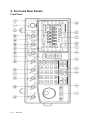
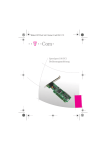
5. Front and Rear Panels
Front Panel
p. 10
GFG-3015
1
POWER button
:
Push the button to turn on the power, and the display is
activated. Push again the button to turn off the power.
2
Main Function keys
:
Key is to set main output waveform in the cycle of
Sine, Triangle and Square. When the key is pressed, the
related waveform LEDs will light up accordingly.
FUNC
Key is to set main frequency entry mode. Key in the
desired value of frequency by using the number keys or
Modify keys and Unit keys.
When the key is pressed, the FREQ LED (on parameter
display area A) will be flashing until other mode is set.
FREQ
Key is to set main amplitude entry mode. Key in the
desired value of voltage by using the number keys or Modify
keys and Unit keys.
When the key is pressed, the AMPL LED (on parameter
display area B) will be flashing until other mode is set.
AMPL
Key is to set main output offset voltage entry mode.
Key in the desired value of voltage by using the number keys
or Modify keys and Unit keys.
When the key is pressed, the OFFS LED (on parameter
display area B) will be flashing until other mode is set.
OFFSET
Key is to set main output Duty Cycle entry mode. Key
in the desired value of percentage by using the number keys
or Modify keys and Unit keys.
When the key is pressed, the DUTY LED (on parameter
display area B) will be flashing until other mode is set.
DUTY
Key is to start performing Amplitude Modulation,
Frequency Modulation or Sweep function. When the key is
pressed again, the functions will stop.
When the key is pressed, the ON/OFF LED (on MOD/SWP
Function LED area) will light up, press again the key, the LED
will be off.
These keys control the functions of sweep and modulation.
MOD/ON
3
Modulation/Sweep
Function keys
:
SOURCE
Key is to set Span of Modulation or Sweep entry
mode and choose the source of modulation.
If set to source choose function, must use Secondary
Function mode.
SPAN
FM
Key is to choose the type of modulation between AM
and FM. If want to set to FM function, must use Secondary
Function mode.
AM
INT/EXT
Key is to set Rate of Modulation, Sweep or Trigger
entry mode and choose the signal source of Modulation,
Sweep or Trigger.
If want to set to signal, must use Secondary Functions mode.
RATE
GFG-3015
p.11
STOP
Key is to set Start Frequency of Sweep entry mode
and Stop Frequency of Sweep entry mode.
If set to Stop Frequency of Sweep entry mode, must use
Secondary Functions mode.
START
LOG S
Key is to choose the type of Sweep between liner
sweep and LOG sweep.
If set to LOG sweep, must use Secondary Function mode.
LIN S
SWP CF
Key is to set the Duty cycle of Modulation, Sweep or
Trigger source entry mode. Key in the desired value of
percentage by using number keys or modify keys and Unit
keys. If want to set to center frequency of Sweep function that
must use Secondary Functions mode.
When the key is pressed, the SYM LED (on parameter
display area B) will be flashing until other mode is set.
When you use center frequency entry mode then the CF LED
(In parameter display area A) will be flashing until other mode
is set.
The detail operation of these keys. Please refer to the
instruction in next Chapter.
SYM
RECL
4
System keys
:
Key is to save or reload the setup parameters of the
instrument into or take out from memory; the selected
DEFAU
numbers
is from 0 to 9, up to 10 groups.
STOR
DEFAU
RS232
RS232
Key is to start performing RS232 interface. Press the
key then use rotational knob to change function states (ON or
OFF).
Press the key again then use rotational knob to change the
Baud rate. The cycle order is in 300, 600, 1200, 2400, 4800,
9600 and 19200 sequence.
If set the instrument to default state, must use Secondary
Function mode.
Key is to set the Secondary Functions mode. When
the key is pressed, the instrument will choose Secondary
Function and the SHIFT LED will light up.
SHIFT
For example, press SHIFT
value of the instrument.
5
Unit keys
p. 12
GFG-3015
:
+
can recall the default
In ‘Normal’ mode, these
keys are used to assign the unit and to set the entered value.
For example, you can use dBm and Vpp to set the output
amplitude. They can be used to set frequency (MHz, kHz, Hz),
OFFSET, and PHASE, etc.
In STOR or RECL modes, they are used as ‘Enter’.
DEG/%
MHz/dB
KHz/Vrms
Hz/Vpp
6
Entry keys
:
9
.
To
and
keys are used to input
value. A unit key should be pressed to set the entered value.
0
key is blank space that used to delete the entered
value entirely and the other function is minus key .
-/BK SP
7
Modify keys
:
Keys are used to change the digit of input
value.
User can use the Rotate knob for increasing or decreasing that
digit.
◄
►
Key to terminate the function of all Modify keys until
user press this key again.
When the key is pressed, the HOLD LED will light up until the
key is pressed again.
HOLD
8
Trigger Function keys
:
Key is to start performing Trigger function mode. If
the key is pressed again, the function will stop.
When the key is pressed, the ON/OFF LED (In Trigger
Function LED area) will light up until the key is pressed again
(The LED will light off).
TRIG ON
Key is to choose the type of Trigger, Single-trigger or
multi-trigger.
When the key is pressed, the MULT or SINGL LED (In
Trigger Function LED area) will light up accordingly.
SIGL/MUT
Key is to set the phase of trigger function entry
mode. Key in the desired value of percentage by using
number keys, modify keys and Unit keys.
When the key is pressed, the PHASE LED (In parameter
display area B) will be flashing until other mode is set.
PHASE
TRIG EXT
Key is to choose the Trigger signal source, internal or
external.
When the key is pressed, the EXT LED (In Trigger Function
LED area) will light up accordingly until the key is pressed
again (The LED will light off).
INT/EXT
9
Counter Function key
:
10
Parameter display
Area (A)
:
Key is to set the Gate time of External counter
GATE
function. The cycle order is according to 0.01s, 0.1s, 1s, and
10s. When the key is pressed, the Gate time LEDs will light up
according user’s wish.
The other function is to choose input signal source of counter,
internal or external, by using Secondary Function mode.
The 6-digit Parameter display presents the parameter values
and information about the current status and unit.
The START LED light on indicated that the value of display
was Start frequency of sweep function right now.
The STOP LED light on indicated that the value of display was
Stop frequency of sweep function right now.
The CF LED light on indicated that the value of display was
center frequency of sweep function right now.
GFG-3015
p.13
11
Parameter display
Area (B)
:
12
Waveform Function
LEDs
Counter Functions
LEDs
Modulation/Sweep
Function LEDs
:
13
14
p. 14
GFG-3015
:
:
The FREQ LED light on indicated that the value of display was
main output frequency right now.
The RATE LED light on indicated that the value of display was
rate frequency of sweep or modulation or trigger function right
now.
The SPAN LED light on indicated that the value of display was
Span frequency of sweep function right now.
The MHz, kHz, Hz and mHz LED light on indicated that unit
according current value of display.
This 4-digit Parameter display presents the parameter values
and information about the current status and unit.
The AMPL LED light on indicated that the value of display was
main output amplitude right now.
The OFFS LED light on indicated that the value of display was
main output DC offset voltage right now.
The DUTY LED light on indicated that the value of display was
main output duty cycle right now.
The SPAN LED light on indicated that the value of display was
span frequency of modulation function right now.
The SYM LED light on indicated that the value of display was
modulation signal duty cycle of sweep or modulation or trigger
function right now.
The PHASE LED light on indicated that the value of display
was phase of trigger function right now.
The STOR LED light on indicated that the value of display was
save group number right now.
The RECL LED light on indicated that the value of display was
reload group number right now.
The V, rms, dBm kHz, Hz, % and DEG LED light on indicated
that unit according current value of display.
These LEDs indicate the figure of main output waveform and
the current operation functions.
These LEDs indicate the GATE TIME of external counter and
the current value.
These LEDs indicate the current status of Sweep and
Modulation and the current operation functions.
The AM LED lights on to indicate the setting status of
amplitude modulation function.
The FM LED lights on to indicate the setting status of
frequency modulation function.
The LIN LED lights on to indicate the setting status of liner
sweep function.
The LOG LED lights on to indicate the setting status of LOG
sweep function.
The Sine, Triangle and Square LED light on indicated that
according Modulation source waveform.
The EXT LED lights on to indicate the external sweep or
modulation signal source.
The ON/OFF LED lights on to indicate that the sweep or
modulation function is enabled.
15
Trigger Function LEDs :
16
Shift mode LED
:
17
Hold mode LED
:
18
RS-232 Interface LED :
19
Main Output BNC
:
20
Sync Output BNC
:
21
TTL Output BNC
22
GCV Output BNC
:
:
23
Modulation/Sweep
Output BNC
24
EXT Modulation/Trigger :
Input BNC
25
VCF Input BNC
26
EXT Counter Input BNC :
These LEDs indicate the current status of trigger function on
display and the current operation functions.
The MULT LED lights on to indicate the trigger setting status
of multi-trigger type.
The SINGL LED lights on to indicate the trigger setting status
of Single-trigger type.
The EXT LED lights on to indicate the external trigger signal
source.
The ON/OFF LED lights on to indicate that the trigger function
is enabled.
The SHIFT LED light on indicated that the enter mode is
Secondary Functions right now.
The HOLD LED lights on to indicate that all modify keys is
disabled.
The RS232 LED indicates the current operation status with the
RS-232 interface bus.
This is the BNC connector that outputs all main signals. Output
resistance is 50Ω.
This is the BNC connector that outputs sync signals. Output
resistance is 50Ω.
This is the BNC connector that outputs TTL level signals.
This is the BNC connector that outputs the voltage between
0.2V and 2V varied with different Frequency
:
:
This is the BNC connector that outputs internal Sweep or
modulation signals. Output Impedance is 10kΩ.
This is the BNC connector for EXT amplitude/frequency
modulation or EXT sweep signal input.
The amplitude modulation index is 100% when ≤10Vpp is
input.
The frequency modulation index is 15% when ≤5Vpp is input.
The trigger mode input signal is compatible with TTL level.
This is the BNC connector for VCF signal input.
The frequency variation width index is 100:1 when 10V± 1V is
input. Input Impedance is 10kΩ.
This is the BNC connector for external counter signal input.
The Input Impedance is 1MΩ // 150pF
GFG-3015
p.15
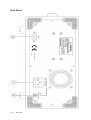
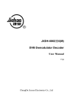
Rear Panel
p. 16
GFG-3015
1
Power Entry model
2
Line Voltage Selector
3
RS232 connector
: This is the AC power input terminal. AC input should be within
the range of line voltage±15%, 50/60Hz.
: This switch can choose the current line voltage between 115V
and 230V
: This is the port of serial RS232 interface. The DCE and Baud
rate is among 300 ~ 19.2k.
GFG-3015
p.17
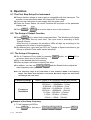
6. Operation
6.1 The First Step Setup For Instrument
n Ensure that the voltage of main supply is compatible with this instrument. The
selector on the rear panel states the required AC line voltage.
o Connect the instrument to main supply with the power cord.
p Press the Power Switch, all control functions will be shown on the parameter
display area.
DEFAU
q Press
SHIFT
+
RS232
can recall the default value of this instrument.
6.2 The Setup of Output Function
n Press FUNC key to select main output waveform. The Waveform will change
when you press this key each time. The cycle order is according to Sine,
Triangle, Square.
When the key is pressed, the waveform LEDs will light up according to the
mentioned cycle order of output waveform.
o Set different duty cycle ratio (not 50%) for Triangle or Square waveform to get
±Ramp or different Pulse width square waveform.
6.3 The Setup of Frequency
n Set to Frequency Entry mode by pressing
button, the FREQ LED (In
FREQ
parameter display area A) will be flashing.
o Key in the desired value of frequency.
p Select a proper unit-button to specify the value.
◄
q In addition, you can use
main frequency value you need.
►
and the Rotate Knob to adjust the
Note: The frequency range of this instrument is from 10mHz to 15MHz in 8 Frequency
Range. The details and resolution is as below. But those ranges will auto switch
according to the enter value.
Frequency Range
Frequency
Resolution
10mHz~15MHz in 8 Frequency Range (auto switch)
1.5001MHz ~ 15.0000MHz …(100Hz)
150.01kHz ~ 1.50000MHz…(10Hz)
15.001kHz ~ 150.000kHz…(1Hz)
1.5001kHz ~ 15.0000kHz…(0.1Hz);
150.01Hz ~ 1.50000kHz…(10mHz)
15.01Hz ~ 150.00Hz…(10mHz)
1.51Hz ~ 15.00Hz…(10mHz)
0.01Hz ~ 1.50Hz…(10mHz)
Example of the Setup Frequency
1. To set frequency at 250Hz
Press
p. 18
GFG-3015
FREQ
first, then key in
2
5
0
and press
Hz/Vpp
.
2. To modify the frequency to 850Hz.
◄
►
Press
or
to move flash digit to “ 2 ” position.
Then turn the Rotate Knob clockwise until the digit become to “ 8 ”.
6.4 The Setup of Amplitude
n Set to Main Amplitude entry mode by pressing
button to, now the AMPL
AMPL
LED (In parameter display area B) will be flashing.
o Key in the desired value of Amplitude.
p Select a proper unit-button to specify the value.
◄
q In addition, you can use
or
main Amplitude value you need.
►
and the Rotate Knob to modify the
Example of the Setup Amplitude
1. To set Amplitude at 8 Vpp.
8
Press AMPL first, then key in
2. To modify the Amplitude to 5 Vpp.
and press
Hz/Vpp
.
◄
►
Press
or
to move flash digit to “ 8 ” position.
Then turn the Rotate Knob anti-clockwise until the digit become to “ 5 ”.
The input limit : (1) Amplitude should be among 0.01 ~ 10Vpp.
(2) Offset should be among ±5Vpp.
(3) AMPL + |2 × OFFSET| ≤ 10Vpp.
6.5 The Setup of Offset
n Set to main DC offset Voltage entry mode by pressing
OFFSET
button, now the
OFFS LED (In parameter display area B) will be flashing.
o Key in the desired value of DC offset voltage.
p Select a proper unit-button to specify the value.
◄
►
q In addition, you can use
main DC offset voltage value you need.
and the Rotate Knob to modify the
Example of the Setup Offset
1. To set DC offset voltage at 1 Vpp.
1
Press OFFSET first, then key in
2. To modify offset voltage to 2 Vpp.
and press
Hz/Vpp
.
►
◄
Press
or
to move flash digit to “ 1 ” position.
Then turn the Rotate Knob clockwise until the digit become to “ 2 ”.
The input limit : (1) Amplitude should be among 0.01 ~ 10Vpp.
(2) Offset should be among ±5Vpp.
(3) AMPL + |2 × OFFSET| ≤ 10Vpp.
GFG-3015
p.19
6.6 The Setup of Duty
n Set Duty cycle of Main output entry mode by pressing
DUTY LED (In parameter display area B) will be flashing.
o Key in the desired value of Duty cycle.
p Key in the specific value by using Unit button.
DUTY
button, the
◄
►
q In addition, you can use
and the Rotate Knob to modify the
Duty cycle of Main output value you need.
Example of the Setup Duty
1. To set Duty cycle at 60%.
Press DUTY
first, then key in
2. To modify Duty cycle to 30%.
6
0
and press
DEG/%
.
◄
►
Press
or
to move flash digit to “ 6 ” position.
Then turn the Rotate Knob anti-clockwise until the digit become to “ 3 ”.
The input limit: 80%:20%:80% at 1MHz.
6.7 The Setting of STORE
The Store button is used to save the setup parameters of the instrument into its
memory with the stored group number from 0 to 9, up to 10 groups totally.
RECL
n Push STOR button.
o Key in the group number from 0 to 9.
p Press any button from
setting.
DEG/%
MHz/dB
kHz/Vms
or
Hz/Vpp
to complete the
Example of the Setup STOR
To save a parameter to the RAM of group #5.
RECL
Press
STOR
first, then key in
and press
5
Hz/Vpp
.
6.8 The Setting of RECALL
The Recall button can retrieve the parameters saved in the RAM.
RECL
n Push SHIFT and STOR button.
o Key in the group number from 0 to 9.
p Press any button from
setting.
DEG/%
MHz/dB
kHz/Vms
or
Hz/Vpp
to complete the
Example of the Setup RECALL
To retrieve a parameters from the RAM of group #6.
RECL
Press
p. 20
SHIFT
GFG-3015
and
STOR
first, then key in
6
and press
Hz/Vpp
6.9 The SHIFT Key and Function Keys
The
button is used to enable the secondary function of certain function
SHIFT
keys with blue printed letters. After pressing the
SHIFT
button, The SHIFT LED
will light up, only the buttons with blue printed letters are working. To release the
secondary function by pressing
SHIFT
again.
The Secondary Functions
DEFAU
1.
SHIFT
2.
SHIFT
+
RS232
Return to the default status of GFG-3015.
RECL
+
STOR
Retrieve the setup parameters from memory;
SWP CF
3.
SHIFT
4.
SHIFT
+
SYM
Display sweep center frequency and get into enter mode.
SOURCE
+
SPAN
Change the Modulation source.
FM
5.
SHIFT
6.
SHIFT
+
AM
Set Frequency modulation function.
INT/EXT
+
RATE
Choose the Modulation type.
STOP
7.
SHIFT
8.
SHIFT
+
START
Display Sweep stop frequency and get into enter mode.
LOG S
+
LIN S
Set LOG sweep function.
INT/EXT
9.
SHIFT
+
GATE
Choose the Counter signal source.
6.10 Setup of LIN or LOG Sweep
GFG-3015 can adopt frequency to sweep its function output for triangle and ramp
waves. The type of sweep can be set as linear or log sweep.
n Select a main waveform by using
FUNC
o Select a main output amplitude by using
button.
AMPL
button.
LOG S
p Select the sweep mode by using
INT/EXT
q Press
RATE
LIN S
button.
to set up sweep RATE value (Range from 0.01Hz to 10kHz).
GFG-3015
p.21
STOP
r Set the starting frequency by pressing
START
button and terminate sweep
STOP
frequency by pressing
SHIFT
+
START
.
The start and stop frequency must be at the same sweep frequency range.
Please refer to the Note 2 for the details.
The sweep can also be done by enter Center frequency or Span frequency.
SWP CF
Press
SHIFT
+
SYM
for center frequency entry mode (Note 3).
SOURCE
Press
SPAN
for span frequency entry mode (Note 3).
SWP CF
s Press
SYM
t Press
MOD/ON
to set the Duty of sweep signal (Range 90%:10%:90%).
to initiate sweeping.
Note: 1. Please refer to the setup of LIN and LOG Sweep as the sample below.
2. Because all frequency range (0.01Hz ~ 15MHz) of GFG-3015 are composed of
8 frequency ranges (The details as below), So the value of start and stop
frequency must be at the same sweep range.
Sweep Range
150kHz ~15MHz
15kHz ~1.5MHz
1.5kHz ~150kHz
150Hz ~15kHz
15Hz ~1.5kHz
1.5Hz ~150Hz
0.15Hz ~15Hz
0.01Hz ~1.5Hz
3. The bandwidth [SPAN] = stop frequency - start frequency
The center frequency = [(stop frequency + start frequency)/2]
The start frequency
= center frequency of the sweep - bandwidth/2
The stop frequency
= center frequency of the sweep + bandwidth/2
The start and stop frequencies can be freely set according to the users’
preference.
4. It won’t make any change on execution and result by taking different step
sequence.
5. GFG-3015 can output waveform synchronizing with its sweep function. In the
example of setting up LIN sweep, the Modulation output terminal will output the
waveform of triangle at 1Hz.
Example of the Setup of LIN Sweep
To set the following conditions:
Output function : Sine Wave.
Output Amplitude : 10Vpp.
Sweep mode : LIN.
Speed :1 second.
p. 22
GFG-3015
Start frequency : 1kHz.
Stop frequency : 10kHz.
Sweep signal symmetry: 50%.
Procedure:
n Press
FUNC
o Press
AMPL
to select SINE wave for main output.
1
0
Hz/Vpp
in sequence.
LOG S
p Then press
to select linear sweep mode.
LIN S
INT/EXT
q Press
RATE
1
Hz/Vpp
in sequence.
1
KHz/Vrms
in sequence.
STOP
r Press
START
STOP
s Press
SHIFT
START
1
0
KHz/Vrms
5
0
DEG/%
in sequence.
SWP CF
t Press
SYM
in sequence.
u Press MOD/ON
v The Modulation/Sweep Output BNC will output 1Hz Triangle wave.
In addition, you can use
value you need.
◄
and the Rotate Knob to modify the
►
Example of the Setup of LOG Sweep
To set the following conditions:
Output function: Triangle Wave.
Output amplitude: 10Vpp.
Sweep mode: LOG.
Speed: 0.1 second.
Start frequency: 10kHz.
Stop frequency: 100kHz.
Sweep signal symmetry: 90%.
Procedure:
n Press
FUNC
o Press
AMPL
to select TRIANGLE wave for main output.
1
0
Hz/Vpp
in sequence.
LOG S
p Then press
SHIFT
to select LOG sweep mode.
LIN S
INT/EXT
q Press
RATE
1
0
Hz/Vpp
in sequence.
1
0
KHz/Vrms
in sequence.
START
1
0
9
0
DEG/%
STOP
r Press
START
STOP
s Press
SHIFT
0
KHz/Vrms
in sequence.
SWP CF
t Press
SYM
in sequence.
GFG-3015
p.23
u Press
.
MOD/ON
v The Modulation/Sweep Output BNC will output the 10Hz LOG wave.
In addition, you can use
value you need.
◄
and the Rotate Knob to modify the
►
Error message for Sweep Function
Because all frequency range (0.01Hz ~ 15MHz) of GFG-3015 are composed of 8
frequency ranges, So the Sweep function has specific restriction on the start and
stop frequency. If the value of start and stop frequency not at the same sweep
range, then the instrument will show the message to user.
Basically, The message is a suggestion that remind user of selecting a proper
sweep frequency range and amend the start or stop frequency.
Please refer to the sample below:
To set the following conditions:
Start frequency: 100Hz.
Stop frequency: 1MHz.
Procedure:
LOG S
n Press
LIN S
to select linear sweep mode.
STOP
o Press
START
1
0
0
Hz/Vpp
in sequence.
STOP
p Press
SHIFT
q Press
MOD/ON
START
1
MHz/dB
in sequence.
.
When the MOD/ON
key is pressed, The Display area will show reminding
message (The detail as below) If the input sweep ranges out of correct range,
The instrument will according to start and stop frequency to suggest possible
sweep range.
In this sample, The message of “15Hz – 1500Hz or 15kHz – 1500kHz” range will
be provided. Because the input start frequency is at 100Hz, so “15Hz – 1.5kHz”
can match up the requirement. Besides, the stop frequency is at 1MHz, so
“15kHz – 1.5MHz” is close to range requirement. After show the message, The
Display area will back to original state (Before press the button).
p. 24
GFG-3015
6.11 Setup of AM Modulation
The AM modulation function offers internal sine, square, and triangle (ramp)
signals. Besides, You can select the modulation signal from external
(Modulation/Trigger Input BNC).
n Set the main output function by using
FUNC
button .
o Set the main output frequency by using
FREQ
button and number keys.
p Set the main output Amplitude by using
AMPL
button and number keys.
FM
q Select the modulation mode by using
AM
button.
INT/EXT
r Select the modulation signal source by using
+
SHIFT
RATE
.
INT/EXT
s Press
RATE
to set up modulation RATE value (Range 0.01Hz ~ 10kHz).
SOURCE
t Select the modulation signal by pressing
SHIFT
+
SPAN
buttons.
GFG-3015 offers sine, square, and triangle (ramp) signals for internal
modulation.
SOURCE
u Select the amplitude modulation depth by pressing
SPAN
buttons (Range
100%).
SWP CF
vPress
SYM
wPress
MOD/ON
to set the Duty of modulation signal (Range 90%:10%:90%).
to start performing amplitude modulation.
Note: 1. Please refer to the setup of amplitude modulation as the example below.
2. When the modulation signal sources from external are selected, the Rate, Span
(Depth), Symmetry and source selection will disable as these functions are
operated on internal source mode only.
3. It won’t make any change on execution and result by taking different step
sequence.
4. GFG-3015 can output waveform synchronizing with its modulation function. In
the example of setting up amplitude modulation, the Modulation output terminal
will output the waveform of sine at 100Hz.
Example of the Setup of AM Modulation
To set the following conditions:
Main function: Sine Wave.
Main Frequency: 10kHz.
Main Output Amplitude:10Vpp
Modulation Mode: Amplitude
Modulation Source: INT
Modulation rate: 100Hz.
Modulation Signal Source: Sine.
Modulation Depth: 80%.
Modulation Signal Symmetry: 50%.
Procedure:
n Press
FUNC
to select SINE wave for main output.
GFG-3015
p.25
o Press
AMPL
p Then press
1
FREQ
0
1
in sequence.
Hz/Vpp
0
KHz/Vrms
in sequence.
.
FM
q Press
AM
to set AM mode.
INT/EXT
r Press
SHIFT
RATE
to select the source from internal signal.
INT/EXT
s Press
RATE
1
0
0
Hz/Vpp
in sequence.
SOURCE
t Press
SHIFT
SPAN
to select the modulation signal on SINE wave.
SOURCE
u Press
SPAN
8
0
DEG/%
in sequence.
5
0
DEG/%
in sequence.
SWP CF
v Press
SYM
w Press MOD/ON .
The MOD Output BNC will output 100Hz sine wave.
In addition, you can use
value you need.
◄
►
and the Rotate Knob to modify the
6.12 Setup of FM Modulation
The FM modulation function offers internal sine, square, and triangle (Ramp)
signals. Besides, you can select the modulation signal from external
(Modulation/Trigger Input BNC).
n Set the main output function by pressing
FUNC
button.
o Set the main output Amplitude by pressing
AMPL
button and number keys.
p Set the main output frequency by pressing
FREQ
button and number keys.
FM
q Select the modulation mode by pressing
SHIFT
+
buttons.
AM
INT/EXT
r Select the modulation signal source by pressing
SHIFT
+
RATE
buttons.
INT/EXT
s Press
RATE
to set up modulation RATE value (Range 0.01Hz ~ 10kHz).
SOURCE
tTo select the modulation signal by pressing SHIFT
and SPAN buttons.
GFG-3015 offers sine, square, and triangle (ramp) signals for internal
modulation.
p. 26
GFG-3015
SOURCE
u To select the Frequency modulation deviation by pressing
SPAN
buttons.
(Range ±15%).
SWP CF
vPress
SYM
wPress
MOD/ON
to set the Duty of modulation signal (Range 90%:10%:90%).
to start performing frequency modulation.
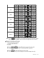
Note: 1. As all frequency range (0.01Hz ~ 15MHz) of GFG-3015 are composed of
8 frequency ranges (The details as below), When the main frequency in
FM function is set, a reasonable Span must be considered.
For example, If set the main frequency at 1.4MHz (Range 7) and set
Span at 10%, the corrected frequency vibration is from 1.26MHz to
1.54MHz and it will be over Range 7. Therefore, the FM result is faults
now, the Span must be reduced in order to get a reasonable result.
Number of Range
8
7
6
5
4
3
2
1
Main Setting Frequency FM variation Range
1.5001MHz ~ 15.0000MHz
150kHz~15MHz
150.01kHz ~ 1.50000MHz
15kHz~1.5MHz
15.001kHz ~ 150.000kHz
1.5kHz~150kHz
1.5001kHz ~ 15.0000kHz
150Hz~15kHz
150.01Hz ~ 1.50000kHz
15Hz~1.5kHz
15.01Hz ~ 150.00Hz
1.5Hz~150Hz
1.51Hz ~ 15.00Hz
0.15Hz~15Hz
0.01Hz ~ 1.50Hz
0.01Hz~1.5Hz
2. Please refer to the setup of frequency modulation as the example below.
3. When the modulation signal source external is selected, the Rate, Span
(Deviation), Symmetry and source selection will disable as those functions
are workable on internal source mode only.
4. It won’t make any change on execution and result by taking different step
sequence.
5. GFG-3015 can output waveform synchronizing with its modulation
function. In the example of setting up frequency modulation, the
“Modulation output terminal” will output the waveform of sine at 1kHz.
Example of the Setup of FM Modulation
To set the following conditions:
Main function: Sine Wave.
Main Frequency: 100kHz.
Main Output Amplitude: 10Vpp.
Modulation Mode: Frequency
Modulation Source: INT
Modulation rate: 1kHz.
Modulation Signal Source: Sine.
Modulation Deviation: 10%.
Modulation Signal Symmetry: 50%.
Procedure:
n Press
FUNC
to select SINE wave for main output.
GFG-3015
p.27
o Press
AMPL
p Then press
1
FREQ
0
1
in sequence.
Hz/Vpp
0
0
in sequence.
KHz/Vrms
FM
q Press
SHIFT
AM
to set FM mode.
INT/EXT
r Press
SHIFT
RATE
to select the source from internal signal.
INT/EXT
s Press
1
RATE
KHz/Vrms
in sequence.
SOURCE
t Press
SHIFT
SPAN
to select the modulation signal on SINE wave.
SOURCE
u Press
SPAN
1
0
DEG/%
in sequence.
5
0
DEG/%
in sequence.
SWP CF
v Press
SYM
w Press MOD/ON .
The MOD Output BNC will output the 1kHz sine wave.
In addition, you can use
◄
►
and the Rotate Knob to modify the
value you need.
6.13 Setup of Trigger
The Trigger function offers internal trigger source signals. Besides, You can
select the signal from external (From Modulation/Trigger Input BNC).
n Set the main output function by pressing
FUNC
button .
o Set the main output Amplitude by pressing
AMPL
button and number keys.
p Set the main output frequency by pressing
FREQ
button and number keys.
q Select the Trigger type by pressing
button.
SIGL/MUT
r Select the Trigger signal source by pressing
TRIG EXT
button.
INT/EXT
s Press
RATE
to set up Trigger signal RATE value (Range 0.01Hz ~ 10kHz).
SWP CF
t Press
SYM
to set the Duty of Internal trigger signal (Range 90%:10%:90%).
u Select the Trigger start Phase by pressing PHASE button and number keys.
GFG-3015 offers -90º ~ +80º range for internal trigger mode.
vPress TRIG ON to start performing Trigger function.
Note: 1. Please refer to the setup of Trigger function as the example below.
p. 28
GFG-3015
2.When the Trigger signal source from external is selected, the Rate,
Phase, and Symmetry will disable as those functions are workable on
internal trigger mode only.
3. It won’t make any change on execution and result by taking different step
sequence.
4.The Trigger function of GFG-3015 must meet the important setting
condition with the Main frequency higher than Trigger rate frequency!
Example of the Setup of Trigger Function
To set the following conditions:
Main function: Sine Wave.
Main Frequency: 5kHz.
Main Output Amplitude: 10Vpp.
Trigger type: Multi-trigger
Trigger Source: INT
Trigger Signal rate: 1kHz.
Trigger Phase: 30º.
Trigger Signal Symmetry: 50%.
Procedure:
n Press
FUNC
o Press
AMPL
p Then press
to select SINE wave for main output.
1
0
FREQ
Hz/Vpp
5
KHz/Vrms
in sequence.
in sequence.
q Press
SIGL/MUT
to set Trigger Type on Multi-Trigger .
r Press
TRIG EXT
to select the source from internal signal.
INT/EXT
s Press
RATE
1
KHz/Vrms
in sequence.
SWP CF
t Press
SYM
5
0
DEG/%
in sequence.
u Press
PHASE
3
0
DEG/%
in sequence.
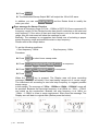
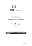
v Press TRIG ON .
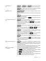
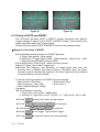
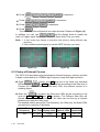
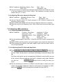
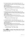
w The Trigger Function will perform on output terminal. Please see Figure (1).
Besides, you can use
you need.
◄
►
and the Rotate Knob to modify the value
Another Example of the Setup of Trigger Function
All the setting conditions are the same as above mentioned examples except the
one set “Single-trigger” of the Trigger Type.
Trigger type: Single-Trigger
Procedure:
n Press SIGL/MUT to set Trigger Type to Single-Trigger .
o The Trigger Function will perform on output terminal. Please see Figure (2).
GFG-3015
p.29
Figure (1)
Figure (2)
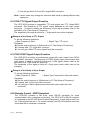
6.14 Setup of GATE and BURST
The GFG-3015 provides GATE or BURST function performed with different
Trigger settings. If want to set to GATE or BURST function, just proceed some
simple calculation and some Trigger setting.
Please refer the setup of GATE or BURST function as the example below.
Example of the Setup of BURST
z The detailed calculated formula for BURST as below:
1. Trigger Rate period = Burst period.
2. Symmetry of Trigger signal =100% - {{[Burst period – (Burst count × Main
Frequency period)]/ Burst period }×100%}
z The Burst period > Burst Count × Main Frequency period.
z Set the Trigger Type to Multi-Trigger type.
z Because the Frequency and Symmetry of Trigger signal have their own
accuracy that is different than main frequency, therefore, when the above
formula is used to calculate the Symmetry, the value might have to be modified
to match the Burst count as desired.
To set the following conditions for BURST function example:
Main function: Sine Wave.
Burst period: 10ms
Main Frequency: 1kHz(1mS).
Burst count: 3.
Main Output Amplitude: 10Vpp.
Procedure:
n The calculation of setting:
1. Trigger Rate = Burst period = 10mS(100Hz)
2. Symmetry of Trigger signal =100% - {{[10mS – (3 × 1mS)]/10mS}×100%}= 30%
o Press
FUNC
p Press
AMPL
q Then press
p. 30
to select Sine wave for main output.
1
FREQ
0
1
Hz/Vpp
KHz/Vrms
in sequence.
in sequence.
r Press
SIGL/MUT
to set Trigger Type on Multi-Trigger .
s Press
TRIG EXT
to select the source from internal signal.
GFG-3015
INT/EXT
t Press
RATE
1
0
0
DEG/%
Hz/Vpp
in sequence.
SWP CF
u Press
SYM
3
0
v Press
PHASE
0
DEG/%
in sequence.
in sequence.
w Press TRIG ON .
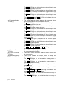
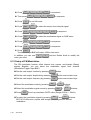
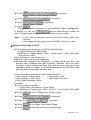
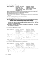
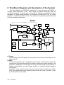
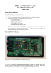
The BURST Function will perform on output terminal. Please see Figure (3).
◄
►
In addition, you can use
and the Rotate Knob to modify the
value of Trigger signal Symmetry and set the Burst count you need.
Note: 1. It won’t make any change on execution and result by taking different step
sequence.
2. Use suitable external signal to set the BURST function you need.
Example of the Setup of GATE
z The detailed calculate formula of GATE function as below:
1.Trigger Rate period = Gate period.
2.Symmetry of Trigger signal = 100% - {[(Gate period – Open Gate time)/
Gate period] ×100%}
z The Gate period > Open Gate time.
z Set the Trigger Type to Multi-Trigger type.
z Because the Frequency and Symmetry of Trigger signal have their own
accuracy that is different than main frequency, therefore, when the above
formula is used to calculate the Open Gate time, the value might have to be
modified to close your desire. It’s a normal phenomenon that the Open Gate
time may have less accuracy than your wish.
To set the following conditions for Gate function Example:
Main function: Triangle Wave.
Gate period: 10mS
Main Frequency: 1kHz(1mS).
Open Gate Time: 6mS.
Main Output Amplitude: 10Vpp.
Procedure:
n The calculation of setting:
1. Trigger Rate = Gate period = 10ms(100Hz)
2. Symmetry of Trigger signal =100% - {[(10mS – 6mS)/10mS]×100%}= 60%
o Press
FUNC
p Press
AMPL
q Then press
to select Triangle wave for main output.
1
FREQ
0
1
Hz/Vpp
KHz/Vrms
in sequence.
in sequence.
r Press
SIGL/MUT
to set Trigger Type to Multi-Trigger.
s Press
TRIG EXT
to select the source from internal signal.
GFG-3015
p.31
INT/EXT
t Press
RATE
1
0
0
DEG/%
Hz/Vpp
in sequence.
SWP CF
u Press
SYM
6
0
v Press
PHASE
0
DEG/%
in sequence.
in sequence.
w Press TRIG ON .
The GATE Function will perform on output terminal. Please see Figure (4).
◄
In addition, you can use
and the Rotate Knob to modify the
►
value of Trigger signal Symmetry and set the Open Gate Time you need.
Note: 1. It won’t make any change on execution and result by taking different step
sequence.
2. Use suitable external signal to set the GATE function you need.
Figure (3)
Figure (4)
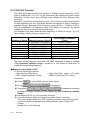
6.15 Setup of External Counter
The GFG-3015 provides a high performance external frequency counter and with
6 digits counter and up to 150MHz high frequency range with high resolution.
INT/EXT
n Press SHIFT
button, the EXT and one of the Gate time indicated
GATE
LEDs will light up, also, the GATE will be flashing according to the Gate time of
Counter (In Counter Functions LEDs area). Now, the external counter is in
enabling status.
INT/EXT
o When the GATE is pressed, the Gate time LEDs will be according to the
cycle of 0.01S, 0.1S, 1S, and 10S to display. The Different Gate time will
provide different resolution of counter. So users can use the key to choose
whatever the resolution they need.
The detailed relation among the Test frequency, the Gate time, the State LEDs
and minimum resolution is as below:
Input Test
Frequency
1Hz
p. 32
GFG-3015
Gate Time Display Value State of LEDs Resolution
100μHz
Hz
0.01 Sec
1.0000
10μHz
Hz
0.1 Sec
1.00000
1 Sec
10 Sec
1.00000
000.000
Hz
mHz, OVER
10μHz
1μHz
10Hz
0.01 Sec
0.1 Sec
1 Sec
10 Sec
10.000
10.0000
10.0000
0.00000
Hz
Hz
Hz
Hz, OVER
1mHz
100μHz
100μHz
10μHz
100Hz
0.01 Sec
0.1 Sec
1 Sec
10 Sec
100.00
100.000
100.000
00.0000
Hz
Hz
Hz
Hz, OVER
10mHz
1mHz
1mHz
100μHz
1kHz
0.01 Sec
0.1 Sec
1 Sec
10 Sec
1.0000
1.00000
1.00000
000.000
kHz
kHz
kHz
Hz, OVER
100mHz
10mHz
10mHz
1mHz
1MHz
0.01 Sec
0.1 Sec
1 Sec
10 Sec
1.0000
1.00000
1.00000
000.000
MHz
MHz
MHz
kHz, OVER
100Hz
10Hz
10Hz
1Hz
10MHz
0.01 Sec
0.1 Sec
1 Sec
10 Sec
10.0000
0.00000
0.00000
000.000
MHz
MHz, OVER
MHz, OVER
kHz, OVER
100Hz
10Hz
10Hz
1Hz
100M Hz
0.01 Sec
0.1 Sec
1 Sec
10 Sec
100.000
00.0000
0.00000
000.000
MHz
MHz, OVER
MHz, OVER
kHz, OVER
1kHz
100Hz
10Hz
1Hz
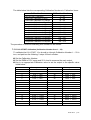
Note: When OVER LED is light on, The means that there are still more values
than 6 digits on the Display. User can set more high Gate time to check it.
Example of the External Counter
To set the following conditions:
Counter mode: External.
Procedure:
INT/EXT
GATE
to select External source for Counter mode.
n Press SHIFT
o Connect the testing signal with “Counter Input BNC connector”.
INT/EXT
p Press GATE to select the Gate time of you need.
q The correct frequency will be displayed. (Parameter display Area (A))
GFG-3015
p.33
6.16 THE VCF Function
The GFG-3015 also provides the function of Voltage control frequency (VCF).
Input a voltage from 0 to 10V to the instrument can change the main output
frequency. In other word, put a different input voltage will get a different main
frequency.
Basically, If user put a voltage that from 0 to 10V to instrument then the variation
of main frequency will over 100 times. But that just appear in Same “Frequency
variation Range”. Because whole frequency range (0.01Hz ~ 15MHz) of GFG3015 is composed of 8 frequency range (The detail is as below). So User’s
voltage just can control at same frequency range.
For example, User can’t make the main frequency to 10kHz on range 7 by VCF
input voltage. It must change to range 6 or 5.
Number of Range Setting Frequency Range
8
1.5001MHz~15.0000MHz
7
150.01kHz~1.50000MHz
6
15.001kHz~150.000kHz
5
1.5001kHz~15.0000kHz
4
150.01Hz~1.50000kHz
3
15.01Hz~150.00Hz
2
1.51Hz~15.00Hz
1
0.01Hz~1.50Hz
VCF Frequency variation
Range
150kHz~15MHz
15kHz~1.5MHz
1.5kHz~150kHz
150Hz~15kHz
15Hz~1.5kHz
1.5Hz~150Hz
0.15Hz~15Hz
0.01Hz~1.5Hz
The input voltage must be input with VCF BNC connector. If need to change
“The frequency variation range”, proceed 6.3 The Setup of Frequency to
modify the main setting frequency.
Example of the Setup of VCF
To set the following conditions:
Main function: Sine Wave.
Main Output Amplitude: 10Vpp.
Hope that Main output will output
10kHz on External VCF function.
Procedure:
n Press
FUNC
o Press
AMPL
to select SINE wave for main output.
1
0
Hz/Vpp
in sequence.
1
5
0
KHz/Vrms
in sequence to choose
p Then press FREQ
suitable main output frequency for corresponding “VCF Frequency variation
Range”.
q Input about DC 9V to “VCF input BNC connector”.
r You will get about 10kHz sine signal from Main Output connector.
Also, you can get 10kHz from VCF frequency variation range with the same
procedure as above description by setting different value of input VCF
voltage.
Please refer to the following:
p. 34
GFG-3015
1
5
KHz/Vrms
1) Press FREQ
in sequence to choose suitable
main output frequency for corresponding “VCF Frequency variation
Range”.
2) Input about DC 3.3V to “VCF input BNC connector”.
3) You will get about 10kHz Sine signal from Main Output connector.
Note: 1. It won’t make any change on execution and result by taking different step
sequence.
2. If need to change difference frequency variation range in order to get
maximum variation (more than 100 times) at the same range, it is to be
suggested to set the main frequency on the top of each frequency range.
6.17 THE GCV Output Function
The GFG-3015 provides the function of Generate control Voltage (GCV). User
can get a voltage from 0.2V to 2V from the instrument and the voltage changes
following the different main output frequency setting. In other words, if change the
setting of the main frequency, the voltage got from GCV output BNC connector
will be changed.
Basically, If user set any main frequency then It will get a relative voltage from
instrument. But that just appear in same “Frequency Range”. Because whole
frequency range (0.01Hz ~ 15MHz) of GFG-3015 are composed of 8 frequency
range (The detail is as below). So the GCV output voltage (0.2 to 2V) just appear
on each same frequency range.
Setting Frequency Range
15.0000MHz ~ 1.5001MHz
1.50000MHz ~ 150.01kHz
150.000kHz ~ 15.001kHz
15.0000kHz ~ 1.5001kHz
1.50000kHz ~ 150.01Hz
150.00Hz ~ 15.01Hz
15.00Hz ~ 1.51Hz
1.50Hz ~ 0.01Hz
GCV Output Voltage
2 ~ 0.2V
2 ~ 0.2V
2 ~ 0.2V
2 ~ 0.2V
2 ~ 0.2V
2 ~ 0.2V
2 ~ 0.2V
2 ~ 0.2V
Example of the Setup of GCV
To set the following conditions:
Get 2V from GCV output BNC connector.
Procedure:
1
5
0
KHz/Vrms
in sequence.
n Press FREQ
o You will get about 2V from GCV output BNC connector.
Also, you can get 2V from another frequency ranges with the same
procedure as above description by setting different frequency value.
Please refer to the following:
1) Press
FREQ
1
5
KHz/Vrms
in sequence.
GFG-3015
p.35
2) You will get about 2V from GCV output BNC connector.
Note: It won’t make any change on execution and result by taking different step
sequence.
6.18 THE TTL Signal Output Function
The GFG-3015 provides a compatible TTL level signal from TTL Output BNC
connector. The frequency of TTL signal output depends on the main output
frequency. If need to modify the frequency of the signal, please refer to the
procedure of 6.3 The Setup of Frequency.
The amplitude of the signal is fixed at ≧3Vpp which can not be changed.
Example of the Setup of TTL Output
To set the following conditions:
Main Frequency: 5kHz.
Signal Type: TTL Level.
Procedure:
n Set the main frequency to 5kHz(refer to 6.3 The Setup of Frequency).
o Connect with “TTL output BNC connector”.
p You will get a 5kHz/TTL Level signal from the connector.
6.19 THE SYNC Signal Output Function
The GFG-3015 provides a synchronous signal with main output from SYNC
Output BNC connector. The frequency of SYNC signal output synchronizes with
main output. If need to modify the frequency of the signal, please refer to the
procedure of 6.3 The Setup of Frequency.
The amplitude of the signal is fixed at >1Vp-p open circuit which can not be
changed.
Example of the Setup of Sync Output
To set the following conditions:
Main Frequency: 10kHz.
Signal Type: Synchronize with main output.
Procedure:
n Set the main frequency to 10kHz(refer to 6.3 The Setup of Frequency).
o Connect with “SYNC output BNC connector”.
p You will get a 10kHz signal synchronized with main output from the
connector.
6.20 Remote Control - RS232 Interface
The GFG3015 contains a DB 9-pin, male RS-232 connector for serial
communication with a computer or terminal. The GFG-3015’s RS-232 interface
is configured as an RS-232 “Data Terminal Equipment” so that data is sent from
pin 3 and received on pin 2. For remote controls, the RS-232 interface has to be
connected with a computer or terminal.
p. 36
GFG-3015
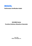
Pin Assignments
The Pin assignments of the RS232 connector on the rear panel for DB-9-D.The
details are listed below.
1 No connection
2 Receive Data (RxD) (input)
3 Transmit Data (TxD) (output)
4 No connection
5 Signal Ground (GND)
6 No connection
7 No connection
8 No connection
9 No connection
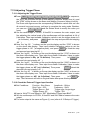
DB9 to DB9 Wiring
The wiring configuration is used for computer with DB9 connectors that
configured as Data Terminal Equipment.
Figure 6.20.1 DB9 to DB9 wiring
When the GFG-3015 is set up with a RS232 interface, please check the following
points:
z Do not connect the output line of one DTE device to the output line of the other.
z Many devices require a constant high signal on one or more input pins.
z Ensure that the signal ground of the equipment is connected to the signal
ground of the external device.
z Ensure that the chassis ground of the equipment is connected to the chassis
ground of the external device.
z Do not use more than 15m of cable to connect devices to a PC.
z Ensure the same configurations are used on the device as the one used on PC
terminal.
z Ensure the connector for the both side of cable and the internal connected line
are met the demand of the instrument.
Communication Mode
The same baud rate and data format must be set to the instrument and the
computer.
The baud rate of the RS-232 interface can be set as listed in the following table.
GFG-3015
p.37
300 Baud
2400 Baud
19200 Baud
600 Baud
4800 Baud
1200 Baud
9600 Baud
The data transmission format is N-8-1 (no parity bit, 8 data bits, 1 stop bits).
Computer’s Connection
A personal computer with a COM port is the essential facility in order to operate
the instruction via RS232 interface.
The connections between GFG-3015 and computer are as follows:
z
z
z
z
Connect one end of a RS232 cable to the computer.
Connect the other end of the cable to the RS232 port on the GFG-3015.
Turn on the GFG-3015.
Turn on the computer.
The RS232 connection testing
If you want to test whether the RS232 connection is working or not, you can send
a command from computer. For instance, using a terminal program send the
query command (uppercase)
*IDN?
Should return the Manufacturer, model number and firmware version in the
following format:
GW,GFG3015,V.1.00
If you do not receive a proper response from the GFG-3015, please check if the
power is on, the RS232 configurations are the same on both sides, and all cable
connections are active.
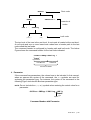
6.21 Commands Syntax
If you want to transfer any of the instructions to an instrument, there are three
basic elements must be included.
z Command header
z Parameter (if required)
z Message terminator or separator
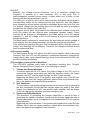
Command Header
The command header has a hierarchical structure that can be represented by a
command tree.
p. 38
GFG-3015
Root node
:SOURce
:SWEep
:WAVeform ?
Lower-lev el
nodes
:SYM ?
:SPACing
1
2
(Linear )
(LOG )
Leaf node
The top level of the tree is the root level. A root node is located at the root level.
A root node and one or more lower-level nodes form a header path to the last
node called the leaf node.
The command header is configured by header path and leaf node. The below
Figure shows the command header for the leaf node indicated.
:SOURce:SWEep:SPACing ?
Root Node
Header Path
Leaf Node
Command Header
Parameter
If the command has parameters, the values have to be included. In this manual,
when we express the syntax of the command, the < > symbols are used for
enclosing the parameter type. For instance, the syntax of the command in the
following Figure includes the Boolean parameter type
NOTE: Do not include the <, >, or | symbols when entering the actual value for a
parameter.
:SOURce:SWEep:SPACing <NR1>
Parameter
T ype
Space
Command Header with Parameter
GFG-3015
p.39
The following Table defines the Boolean and other parameter types for the
GFG-3015.
Parameter
Type
Boolean
Boolean numbers or values
NR1
NR2
NR3
NRf
Integers
Decimal numbers
Floating point numbers
NR1, NR2, or NR3
Description
Example
1
0
0, 1, 18
1.5, 3.141, 8.4
4.5E-1, 8.25E+1
1, 1.5, 4.5E-1
Parameter Types for Syntax Descriptions
For the actual value of the parameter type <Boolean>, you have to enter 0
instead of “OFF” or enter 1 instead of “ON”.
The following example includes both the header and a value for the parameter
type:
:SOURce:TRIGger:STATe 0
The parameter values which appear in this manual are often separated by a
vertical line. This vertical line means the word "or". For example, values for the
parameter <Boolean> are
0|1
This means "0 (off) or 1 (on)", any single value is a valid parameter.
Message Terminator
As there is no signal of end message on RS232 bus, therefore use LF (Line
Feed, 0 × 0A, or ASCII ‘\n’) as message of terminator. When a series of
commands are sent to the instrument, they must add a LF to be a judgment for
message terminator. As for query command, the return message of the
instrument is also added a LF for PC to judge message terminator.
Entering Commands
The standard, which governs the commands setting for the GFG-3015, is
allowed a certain amount of flexibility when you enter commands. For instance,
you can abbreviate many commands or combine commands into one message
to send to the GFG-3015. This flexibility, called friendly listening, saves
programming time and makes the command setting easier to be remembered
and used.
Command Characters
The GFG-3015 is not sensitive to the command characters. You can enter
commands in either uppercase or lowercase.
You can precede any command with white space characters. You must, however,
use at least one space between the parameter and the command header.
p. 40
GFG-3015
Abbreviating Commands
Most commands have both long form and short form. The list for each command
in this section shows the abbreviations in upper case. For instance, you can
enter the query
:SOURce:TRIGger:STATe ?
simply as:
:SOUR:TRIG:STAT ?
6.22 The Commands of RS-232 Serial Interface
Common commands
Command
*CLS
*IDN?
*RCL
*SAV
*RST
Function
Clear status command
Identification query
Recall command
Save command
Default setting
Parameter Arguments
None
None
<NR1>
<0~9>
<NR1>
<0-9>
Commands of the instrument
Command
:SYSTem:ERR ?
:FUNCtion:WAVeform
:FUNCtion:WAVeform ?
:FREQuency
:FREQeency ?
:AMPLitude:VOLTage
:AMPLitude:VOLTage ?
:AMPLitude:UNIT
:AMPLitude:UNIT ?
:OFFSet
:OFFSet ?
:DUTY
:DUTY ?
:SOURce:WAVeform
Function
Check the type of error
messages
Set the waveform of main
frequency
Parameter Arguments
None
<NR1>
Check the present waveform
of main frequency
Set the main frequency
<NRf>
Check the main frequency
Set the value of output
<NRf>
amplitude
Check the value of output
amplitude
Set the unit of amplitude
<NR1>
Check the unit of amplitude
Set the voltage of offset
<NRf>
Check the voltage of offset
Set the value of duty
<NR1>
Check the value of duty
Set the waveform of
<NR1>
modulation mode
<1>Sinusoid
<2>Triangle
<3>Square
None
Numeric data
None
Numeric data
None
<1>Vpp
<2>Vrms
<3>dBm
None
Numeric data
None
Numeric data
None
<1>Sinusoid
<2>Triangle
<3>Square
GFG-3015
p.41
Command
:SOURce:WAVeform ?
:SOURce:STATe
:SOURce:STATe ?
:SOURce:SOURce
:SOURce:SOURce ?
:SOURce:MODAM:RATe
:SOURce:MODAM:RATe ?
:SOURce: MODAM:SPAN
:SOURce: MODAM:SPAN ?
:SOURce: MODAM:SYM
:SOURce: MODAM:SYM ?
:SOURce: MODFM:RATe
:SOURce: MODFM:RATe ?
:SOURce: MODFM:SPAN
:SOURce: MODFM:SPAN ?
:SOURce: MODFM:SYM
:SOURce: MODFM:SYM ?
:SOURce:SWEep:STARt
:SOURce:SWEep:STARt ?
:SOURce:SWEep:STOP
:SOURce:SWEep:STOP ?
:SOURce:SWEep:CENTer
:SOURce:SWEep:CENTer ?
:SOURce:SWEep:SPAN
:SOURce:SWEep:SPAN ?
:SOURce:SWEep:RATe
:SOURce:SWEep:RATe ?
:SOURce:SWEep:SYM
:SOURce:SWEep:SYM ?
p. 42
GFG-3015
Function
Parameter Arguments
Check the present waveform
of modulation mode
Set the modulation function <NR1>
Check the modulation
function
Set the modulation source
Check the modulation
source
Set the value of AM Rate
Check the value of AM Rate
Set the value of AM span
Check the value of AM span
Set the value of AM SYM
Check the value of AM SYM
Set the value of FM Rate
Check the value of FM Rate
Set the value of FM span
Check the value of FM span
Set the value of FM SYM
Check the value of FM SYM
Set the value of sweep start
frequency
Check the value of sweep
start frequency
Set the value of sweep stop
frequency
Check the value of sweep
stop frequency
Set the value of sweep
center frequency
Check the value of sweep
center frequency
Set the value of sweep span
Check the value of sweep
span
Set the value of sweep rate
Check the value of sweep
rate
Set the value of sweep SYM
Check the value of sweep
SYM
None
<0>OFF
<1>AM
<2>FM
<3>Sweep
None
<NR1>
<0>Internal
<1>External
None
<NRf>
Numeric data
None
Numeric data
None
Numeric data
None
Numeric data
None
Numeric data
None
Numeric data
None
Numeric data
<NR1>
<NR1>
<NRf>
<NR1>
<NR1>
<NRf>
None
<NRf>
Numeric data
None
<NRf>
Numeric data
None
<NRf>
Numeric data
None
<NRf>
Numeric data
None
<NR1>
Numeric data
None
Command
:SOURce:SWEep:SPACing
:SOURce:SWEep:SPACing ?
:SOURce:TRIGger:RATe
:SOURce:TRIGger:RATe ?
:SOURce:TRIGger:STATe
Function
Parameter Arguments
Set the method of sweep <NR1>
Check the method of
sweep
Set the value of trigger <NRf>
rate
Check the value of trigger
rate
Set the trigger state
<NR1>
:SOURce:TRIGger:MODe
Check the trigger state
Set the value of trigger <NR1>
phase
Check the value of trigger
phase
Set the trigger mode
<NR1>
:SOURce:TRIGger:MODe ?
:SOURce:TRIGger:SOURce
Check the trigger mode
Set the trigger source
:SOURce:TRIGger:SOURce ?
:SOURce:TRIGger: SYM
Check the trigger source
Set the value of trigger <NR1>
SYM
Check the value of trigger
SYM
Set the gate time of
<NR1>
counter
:SOURce:TRIGger:STATe ?
:SOURce:TRIGger:PHASe
:SOURce:TRIGger:PHASe ?
:SOURce:TRIGger: SYM ?
:SOURce:COUNter:GATe
:SOURce:COUNter:SOURce
Check the gate time of
counter
Set the counter source
:SOURce:COUNter:SOURce ?
Check the counter source
:SOURce:COUNter:GATe ?
<NR1>
<NR1>
<0>Linear
<1>LOG
None
Numeric data
None
<1>ON
<0>OFF
None
Numeric data
None
<0>Single
<1>Mutiple
None
<0> Internal
<1> External
None
Numeric data
None
<0>001sec
<1>01sec
<2>1sec
<3>10sec
None
<0> Internal
<1> External
GFG-3015
p.43
Error Messages
z Command Error
SCPI Error Code/Explanation
Error Code
-100
-102
Command error
Syntax error
z Execution Error
Error Code
SCPI Error Code/Explanation
-220
-221
-222
Parameter error
Settings conflict
Data out of range
6.23 The Examples of the Communication Interface Software
/*
************************************************************************
* Microsoft Visual C++ 6.0 for RS-232
*
* This programming example shows how to communicate
* PC and instrument via RS232.
*
*
"*IDN?\n"
: Ask the Manufacturer, model number
*
and firmware
* ":FREQuency 1000.0\n" : Set Frequency=1000Hz
*
**************************************************************************
*/
#include <stdio.h>
#include <windows.h>
HANDLE InitCom (int Error_Value);
char *Error_Message[6]={
"Error Create File\n",
"Error SetCommTimeous\n",
"Error SetCommState\n",
"Error SetupComm\n",
"Error GetCommState\n",
"Error EscapeCommFunction\n"
};
void main()
{
char
char
char
DWORD
int
HANDLE
p. 44
GFG-3015
command_line[100];
Receive_Data[100];
Read_Machine_Number[10] ={"*IDN?\n"};
dwcommand_len=0,dwWritten=0,dwRead=0;
i,error_value=0;
hComm;
/*---------------- initial Data ---------------*/
for(i = 0; i<100;i++) command_line[i]=0;
for(i = 0; i<100;i++) Receive_Data[i]=0;
/*---------------- Create Comm_port -----------*/
hComm = InitCom(error_value);
/*---------------- Send *IDN? -----------------*/
dwcommand_len =sprintf( command_line,"*IDN?\n"); // ‘\n’ is message
// terminator
WriteFile(hComm,command_line,dwcommand_len,&dwWritten,NULL);
Sleep(1000); // delay 1 sec for instrument response
ReadFile(hComm,Receive_Data,100,&dwRead,NULL);
Receive_Data[strlen(Receive_Data)] = 0x00;
printf("\nReceive_Data = %s\n",Receive_Data);
/*-------------- Send FRQuency = 1000Hz -----------*/
dwcommand_len =sprintf( command_line,":FREQuency %3.0f\n",1000.0);
// ‘\n’ is message terminator
WriteFile(hComm,command_line,dwcommand_len,&dwWritten,NULL);
CloseHandle(hComm);
}
/*---------------------------------------------*/
/*
Initial RS-232
/*---------------------------------------------*/
HANDLE InitCom(int Error_Value)
{
HANDLE
hComm;
COMMTIMEOUTS CommTimeOuts;
*/
hComm = CreateFile("COM1",
GENERIC_READ | GENERIC_WRITE, 0, NULL, OPEN_EXISTING,NULL, NULL );
if (hComm == INVALID_HANDLE_VALUE)
{
printf("%s",Error_Message[0]);
return FALSE;
}
/*----------------- Timeout -------------------*/
CommTimeOuts.ReadIntervalTimeout = 1;
CommTimeOuts.ReadTotalTimeoutMultiplier = 0;
CommTimeOuts.ReadTotalTimeoutConstant = 1000;
CommTimeOuts.WriteTotalTimeoutMultiplier = 0;
CommTimeOuts.WriteTotalTimeoutConstant = 5000;
if(!SetCommTimeouts(hComm, &CommTimeOuts ))
{
printf("%s",Error_Message[1]);
return FALSE;
}
GFG-3015
p.45
/*-----------------------------------------------*/
/*
set baud rate
/*
ByteSize
/*
parity
/*
StopBits
/*-----------------------------------------------*/
DCB dcb = {0};
dcb.DCBlength = sizeof(dcb);
if (!GetCommState(hComm, &dcb))
{
printf("%s",Error_Message[2]);
return FALSE;
}
dcb.BaudRate = CBR_9600; // current baud rate
dcb.ByteSize = 8;
// number of bits/byte, 4-8
dcb.Parity = 0;
// 0-4=no,odd,even,mark,space
dcb.StopBits=0;
// 0,1,2 = 1, 1.5, 2
if (!SetCommState(hComm, &dcb))
{
printf("%s",Error_Message[3]);
return FALSE;
}
/*---------------- Set In,Out Queue -----------*/
if(!SetupComm(hComm, 8196,8196))
{
printf("%s",Error_Message[4]);
return FALSE;
}
if (!EscapeCommFunction(hComm, SETDTR))
{
printf("%s",Error_Message[5]);
return FALSE;
}
return hComm;
}
p. 46
GFG-3015
*/
*/
*/
*/
6.24 The Error message of instrument
The operation of GFG-3015 is a whole digitizing operation user interface. Every
parameter will be showing by numerically and every input value keyed in with
numerical keys. So when key in the value to instrument, it might cause some
mistake, now the GFG-3015 will show a corresponding error code on the Display
a few seconds later for User to correct the data. (Please refer to the specification
or Operation ways). The detailed explanation is as following table:
Error Code
E01
E02
E03
E04
E05
E06
E07
E08
E09
E10
E11
E12
E13
E14
E15
E16
E17
E18
E19
E20
E21
E22
E23
Explanation
Frequency over range
Frequency over Resolution
Amplitude over range
Amplitude over resolution
Offset over range
Offset over resolution
Duty over range
Duty over resolution
Mod rate over range
Mod rate over resolution
Mod sym over range
Mod sym over resolution
Sweep freq over range
Sweep freq over resolution
AM span over range
AM span over resolution
FM span over range
FM span over resolution
Trigger phase over range
Trigger phase resolution
Store setting over settng numbers range
Recall setting over settng numbers range
Recall set is no data
GFG-3015
p.47
7. Adjustment and Correction
7.1 Preparation
n The essential equipment listed as follows:
Instrument
Critical Specification
Oscilloscope
Over 100MHz Bandwidth
Over 200MHz Test Frequency Range. The
Counter
Frequency Resolution must cover GFG3015.
AC/DC Voltmeter
4 1/2 Digit DC accuracy
Distortion Meter (or Audio Analyzer) Over 10Hz to 100kHz Test Range.
DC power supply
Over 20V/0.5A Supply
Over 150MHz Output Frequency Range,
RF Signal Generator
The Frequency Accuracy must cover GFG3015.
Lower 5 Hz Output Frequency Range. The
Signal Generator
Frequency Accuracy must cover GFG-3015
Over 100MHz Bandwidth,
RF Spectrum Analyzer
Amplitude: ±0.5dB
50 Ω Terminator
50 Ω±0.2%, 1W
o The warm-up time of the instrument should be more than 30 minutes.
p The operation temperature should be at 23±5oC, and the humidity should be
lower than PH80%.
q Calling “System Default Calibration Data”. The detail as following:
Press
SHIFT
3
0
1
5
0
HOLD
all the LEDs (Except GATE and OVER) will light up, then press
in sequence,
SHIFT
key
again, all calibration values will be cleared. So don't make a rash decision to
do it.
ª After proceed the step, all calibration values will be lost and the “default setting”
will be recalled.
7.2 Adjust and Check up the operation DC Voltage
n Set the DMM to DCV range to measure the particular test point.
o Adjust the adjust points and check up the operation DC voltage according to
the following table:
Test Point
Adjust Point
Correct Voltage Value
TP122
SVR120
18V ± 0.01V
TP124
SVR121
-18V ± 0.01V
TP131
CHECK
15V ± 0.75V
TP141
CHECK
-15V ± 0.75V
TP112
CHECK
5V ± 0.25V
TP150
CHECK
5V ± 0.25V
U921 PIN1
CHECK
-5V ± 0.25V
p. 48
GFG-3015
7.3 Adjusting Main Clock
n Set Conditions: Set to “External Counter mode”, Gate Time: 1 second
o Connect a standard signal of 10.000000MHz to “EXT Counter Input BNC
connector”
p Adjust VC1021 until the “0.00000” MHz is shown on the display. In the
meantime, The OVER LED will light up.
q Change the Gate time to 10 second, then check the displayed value which
must be smaller than “000.050” kHz.
7.4 Adjusting Sensitivity of counter
n Set Conditions: Set to “External Counter mode”, Gate Time: 0.1 second
o Connect a standard signal of 100.0000MHz with 50 Ω load to “EXT Counter
Input BNC connector”.
p Adjust VR1000 until “00.0000” is shown on the display (Make minimum
amplitude level of that 100.0000MHz signal).
q Check full range of input frequency from 5Hz to 150MHz that must be smaller
than 35mVrms (5Hz~100MHz) and 45mVrms (100MHz~150MHz). If found any
frequency range over the specification, readjust VR1000 until it meets the
sensitivity specification and recheck full range of input frequency again.
7.5 Adjusting VCF Function 100:1
n Set Conditions:
Function : Square Wave Amplitude : 10Vp-p
Duty Cycle : 50%
Frequency : 15kHz
Modulation : OFF
o Input a DC 10±1V to “VCF BNC connector”.
p Set the oscilloscope to 2V/DIV, 0.5ms/DIV and Positive trigger slope to
measure the main output. Then adjust VR215 until the positive duty cycle is full
of 10 divisions.
q Change the trigger slope of oscilloscope to negative and adjust VR212 until the
negative duty cycle is also full of 10 divisions.
r Use the Counter to measure the output.
s The frequency of output must be smaller than 150Hz.
7.6 Adjusting Main Frequency , Duty Cycle and GCV Output Check
n Press
SHIFT
3
0
1
5
1
HOLD
o The “ CaL….” will be shown on the up side display (Parameter display Area (A)),
and “Freq” will be shown on the down side display (Parameter display Area
(B)). Now, the GFG-3015 is in Duty calibration states. Please wait for few
minutes.
p Wait about 12 minutes, the instrument will be back to original state.
q Set Conditions:
Function : Square Wave Amplitude : 10Vp-p
Duty Cycle : 50%
Frequency : 15kHz
Modulation : OFF
r Set the DMM to DCV range to measure the GCV output terminal.
s Check the Voltage of GCV output which must be at 1.8V to 2.2V.
GFG-3015
p.49
t Check the GCV output voltage (0.2 ~ 2V) which just appears on the same
frequency range. The detail is as follows:
Setting Frequency Range
15.0000MHz ~ 1.5001MHz
1.50000MHz ~ 150.01kHz
150.000kHz ~ 15.001kHz
15.0000kHz ~ 1.5001kHz
1.50000kHz ~ 150.01Hz
150.00Hz ~ 15.01Hz
15.00Hz ~ 1.51Hz
1.50Hz ~ 0.01Hz
GCV Output Voltage
2 ~ 0.2V
2 ~ 0.2V
2 ~ 0.2V
2 ~ 0.2V
2 ~ 0.2V
2 ~ 0.2V
2 ~ 0.2V
2 ~ 0.2V
7.7 Adjusting Rise/Fall Time
n Set Conditions:
Function : Square Wave Amplitude : 10Vp-p
Duty Cycle : 50%
Frequency : 1MHz
Modulation : OFF
o Use an oscilloscope with 50 Ω load to measure the main output. Then adjust
VC940 until the Rise or Fall time is smaller than 18ns.
p The Overshot of square wave must be smaller than 10% of Output amplitude.
7.8 Adjusting Main Sine wave Harmonic Distortion
n Set Conditions:
Function : Sine Wave
Amplitude : 10Vp-p
Duty Cycle : 50%
Frequency : 1kHz
Modulation : OFF
o Set the Distortion meter (Or Audio analyzer) to 50 Ω load to measure the main
output.
p Adjust VR420 and VR430 until the minimum distortion harmonic is reached.
q Check the value for full frequency from 10Hz~100kHz that must be smaller
than 0.5%(-46dBc).
r Set Conditions:
Frequency : 15MHz
Amplitude : 1Vp-p
s Set the spectrum analyzer to 50 Ω load, adjust the start frequency at 0Hz and
the stop frequency at 100MHz, to measure the main output.
t Check the value of full frequency from 100kHz~15MHz that must be smaller
than -30dBc.
7.9 Adjusting Modulation source
7.9.1 Adjusting Rate and symmetry
0
1
5
2
HOLD
3
n Press SHIFT
in sequence,
the “CaL…” will be shown on the display A(Parameter display Area (A)), and
the “RATE” will be shown on the display B(Parameter display Area (B)). Now,
the GFG-3015 is in Rate calibration state.
o Wait about 3 minutes, the instrument will be back to original state. That means
the calibration is completed.
p. 50
GFG-3015
p Set Conditions: Modulation Source : Sine
Rate : 1kHz
SYM : 50%
Modulation : ON
q Use the Counter to measure the Modulation/Sweep Output and Check the value
of full rate frequency from 0.01Hz~10kHz. The frequency accuracy must be
smaller than 5% ±1 count.
7.9.2 Adjusting Sine wave Harmonic Distortion
n Set Conditions:
Modulation Source : Sine
Rate : 1kHz
SYM : 50%
Modulation : ON
o Set the Distortion meter (Or Audio analyzer) to 50 Ω load to measure the
Modulation /Sweep Output.
p Adjust VR680 and VR690 until the minimum distortion harmonic is reached.
q Check the value of full frequency from 10Hz~10kHz that must be smaller than
2%.
7.10 Adjusting AM modulation
7.10.1 Adjusting Modulation Balance
n Set Conditions:
Function : Sine Wave
Amplitude : 0.1Vp-p
Duty Cycle : 50%
Frequency : 1MHz
Modulation Source : Sine Modulation Type : AM
SYM : 50%
RATE : 1kHz
Span : 100%
Modulation : ON
o Set the oscilloscope to 20mV/DIV, 0.5ms/DIV and 50 Ω load to measure the
output.
p Adjust VR800 until the positive cycle and negative cycle reach the same level.
q Check whether the positive cycle and negative cycle reach the same level or
not at 8Vpp amplitude.
7.10.2 Adjusting Span,DC offset and Amplitude
3
0
1
5
3
HOLD
n Press SHIFT
in sequence,
the “ASP 1” will be shown on the up side display (Parameter display Area (A)),
and the ”2400” will be shown on the down side display (Parameter display Area
(B)).
The Down side figures are the corresponding Calibration values which can use
all the numeric keys and use any unit keys to complete entry mode. Besides,
you can use
◄
and ►the Rotate Knob to modify the value you
need.
o Set the oscilloscope to 2V/DIV, 0.2mS/DIV and 50Ω load to measure the main
output. Input suitable Calibration values to set the span of modulation to 100%,
then press HOLD to finish the step and proceed next step (ASP 2).
GFG-3015
p.51
p Now, the “ASP 2” is shown on the up side display and the “2450” is shown on
the down side display. Set the oscilloscope to 2V/DIV, 0.2mS/DIV and 50Ω
load to measure the main output. Input suitable Calibration values to set the
Amplitude to 10Vpp, then press HOLD
to finish the step and proceed next
step(ASP 3).
q Now, the “ASP 3” is shown on the up side display and the “2390” is shown on
the down side display. Set the oscilloscope to 2V/DIV, 0.2mS/DIV and 50Ω
load to measure the main output. Input suitable Calibration values to set the
HOLD
span of modulation to 100%, then press
to finish the step and
proceed next step(ASP 4).
r Now, the “ASP 4” is shown on the up side display and the “2460” is shown on
the down side display. Set the oscilloscope to 2V/DIV, 0.2mS/DIV and 50Ω
load to measure the main output. Input suitable Calibration values to set the
Amplitude to 10Vpp, then press HOLD to finish the step and proceed next
step (ASP 5).
s Now, the “ASP 5” is shown on the up side display and the “2280” is shown on
the down side display. Set the oscilloscope to 2V/DIV, 0.2mS/DIV and 50Ω
load to measure the main output. Input suitable Calibration values to set the
HOLD
span of modulation to 100%, then press
to finish the step and proceed
next step(ASP 6).
t Now, the “ASP 6” is shown on the up side display and the “2610” is shown on
the down side display. Set the oscilloscope to 2V/DIV, 0.2mS/DIV and 50Ω
load to measure the main output. Input suitable Calibration values to set the
Amplitude to 100%, then press HOLD to finish the step and proceed next
step(ASP 7).
u Now, the “ASP 7” is shown on the up side display and the “2040” is shown on
the down side display. Set the DMM to DCV range and 50 Ω load to measure
the main output. Input suitable Calibration values to set the DC offset to
0.000V, then press HOLD to finish the step and the instrument will be back
to original state.
7.10.3 Check the Modulation Bandwidth
n Set Conditions:
Function : Sine Wave
Amplitude : 10Vp-p
Duty Cycle : 50%
Frequency : 100kHz
Modulation Source : Sine Modulation Type : AM
SYM : 50%
RATE : 1kHz
Span : 100%
Modulation : ON
o Set the oscilloscope to 1V/DIV, 0.2ms/DIV and 50 Ω load to measure the main
output. Then fine adjusting the vertical scale of oscilloscope until the amplitude
is full of 8 divisions.
p. 52
GFG-3015
p Set Conditions:
Frequency : 5MHz
q The Amplitude of waveform must be over 6 divisions.
7.10.4 Check the Modulation Output
n Set Conditions:
Function : Sine Wave
Amplitude : 10Vp-p
Duty Cycle : 50%
Frequency : 100kHz
Modulation Source : Sine Modulation Type : AM
SYM : 50%
RATE : 1kHz
Span : 100%
Modulation : ON
o Set the oscilloscope to 1V/DIV, 0.5ms/DIV to measure the “MOD Output BNC”.
p The BNC connector will output 1kHz sine wave and the amplitude must be ≧
1Vpp.
7.10.5 Check the External Modulation input function
n Set Conditions:
Function : Sine Wave
Amplitude : 10Vp-p
Duty Cycle : 50%
Frequency : 5MHz
Signal Source : Exit
Modulation Type : AM
Modulation : ON
o Input a 10Vpp/100kHz Sine wave to “EXT Modulation/Trigger Input BNC”.
p Set the oscilloscope to 2V/DIV, 2us/DIV and 50Ω load to measure the main
output.
q The Span of AM modulation must be ≧100% now.
r Input another signal from 10Vpp/10Hz to 1MHz Sine wave to “EXT Modulation
/Trigger Input BNC” and check the Span which must be ≧100%.
7.11 Adjusting FM and Sweep Function
7.11.1 Adjusting the Span of FM
3
0
1
5
4
HOLD
nPress SHIFT
in sequence,
the “CaL…” will be shown on the display A (Parameter display Area (A)), and
the “FSP” will be shown on the display B (Parameter display Area (B)). Now,
the GFG-3015 is in calibration state.
o Wait about 5 minutes, the instrument will be back to original state. That means
the calibration is completed.
p Set Conditions:
Function : Sine Wave
Amplitude : 10Vp-p
Duty Cycle : 50%
Frequency : 100kHz
Signal Source : Sine
Modulation Type : FM
Span : 15%
Modulation : ON
q Set the oscilloscope to 2V/DIV, 1us/DIV and 50 Ω load to measure the main
output.
r The Span of FM modulation must be ≧15% now.
The maximum frequency must be ≧115kHz
The minimum frequency must be ≦85kHz
GFG-3015
p.53
7.11.2 Adjusting the LOG sweep
n Set Conditions:
Function : Sine Wave
Amplitude : 10Vp-p
Duty Cycle : 50%
Frequency : 10kHz
Sweep Type : LIN
Start Frequency : 150Hz
Stop Frequency : 15kHz RATE : 10kHz
Modulation : ON
o Set the oscilloscope to 5V/DIV, 20us/DIV to measure the “MOD Output BNC”.
p Record the positive peak level value of the waveform
q Change the Sweep type from LIN to LOG.
r Adjust VR720 until the positive peak level value reaches the same level as
step p.
s Check the amplitude which must be over 10Vpp.
7.11.3 Adjusting the Span of Sweep
3
0
1
5
5
HOLD
nPress SHIFT
in sequence,
the “CaL…” will be shown on the display A (Parameter display Area (A), the
“LIN” or “LOG” will be on the display B (Parameter display Area (B)). Now, the
GFG-3015 is in calibration state.
o Wait about 5 minutes, the instrument will be back to original state. That means
the calibration is completed.
7.11.4 Check the Modulation Output
n Set Conditions:
Function : Sine Wave
Amplitude : 10Vp-p
Duty Cycle : 50%
Frequency : 100kHz
Modulation Source : Sine Modulation Type : FM
SYM : 50%
RATE : 1kHz
Span : 15%
Modulation : ON
o Set an oscilloscope to 1V/DIV, 0.5ms/DIV to measure the “MOD Output BNC”.
p The BNC connector will output 1kHz sine wave and the amplitude must be ≧
1Vpp.
q Set Conditions:
Sweep Type : LIN
Start Frequency : 150Hz
Stop Frequency : 15kHz RATE : 1kHz
Modulation : ON
r The BNC connector will output 1kHz Ramp wave and the amplitude must be
≥-5Vp-p into 10k Ω.
7.11.5 Check the External Modulation input function
n Set Conditions:
Function : Sine Wave
Amplitude : 10Vp-p
Duty Cycle : 50%
Frequency : 100kHz
Signal Source : Exit
Modulation Type : FM
Modulation : ON
o Input a 5Vpp/20kHz Sine wave to “EXT Modulation/Trigger Input BNC”.
p Set the oscilloscope to 2V/DIV, 1us/DIV and 50 Ω load to measure the main
output.
q The Span of FM modulation must be ≧15% now.
The maximum frequency must be ≧115kHz.
The minimum frequency must be ≦85kHz.
p. 54
GFG-3015
7.12 Adjusting Trigger Phase
7.12.1 Adjusting the Trigger Phase
3
0
1
5
6
HOLD
nPress SHIFT
in sequence,
the “trg 0” will be shown on the up side display (Parameter display Area (A)), and
the ”3190” will be shown on the down side display (Parameter display Area (B)).
The Down side figures are the corresponding Calibration values that can use
all numeric keys and use any unit keys to complete the entry mode. Besides,
you can use
and the Rotate Knob to modify the value you
►
◄
need.
o Set the oscilloscope to 1V/DIV, 0.2ms/DIV to measure the main output, and
fine adjusting the vertical scale of the oscilloscope until the amplitude is full of
8 divisions. Then input suitable Calibration values to set the trigger phase to 0
∘(at 4 division), and press
HOLDto finish the step and proceed next step(trg
-90∘).
p Now, the “trg -90∘” is shown on the up side display and the “3700” is shown
on the down side display. Then input suitable Calibration values to set the
trigger phase to -90∘(at negative peak), and press HOLD to finish the step
and proceed next step(trg 80∘).
q Now, the “trg 80∘”is shown on the up side display and the “2700” is shown on
the down side display now. Then input the suitable Calibration Value to make
HOLD this
the trigger phase on 80∘(at 7.6 division). Then press
to finished
step and into next step(trg 45∘).
r Now, the “trg 45∘”is shown on the up side display and the “2920” is shown on
the down side display now. Then input the suitable Calibration Value to make
HOLD
the trigger phase on 45∘(at 6 division). Then press
to finished this
step and into next step(trg -45∘).
r Now, the “trg -45∘”is shown on the up side display and the “3450” is shown on
the down side display now. Then input the suitable Calibration Value to make
HOLD this
the trigger phase on -45∘(at 2 division). Then press
to finished
step. The instrument will back to Original states after press this key now.
7.12.2 Check the External Trigger input function
n Set Conditions:
Function : Sine Wave
Amplitude : 10Vp-p
Duty Cycle : 50%
Frequency : 5kHz
Trigger Source : Exit
Trigger type: Single-trigger
Trigger Phase: 30º
Trigger : ON
o Input a 1kHz/TTL level signal to “EXT Modulation/Trigger Input BNC”.
p Set the oscilloscope to 2V/DIV, 0.2ms/DIV and 50Ω load to measure the main
output.
q The main output is the same as Figure (1) now (refer to 6.13 Setup of Trigger).
GFG-3015
p.55
7.13 Calibrating by Software
Manual Calibration
Basic Steps introduction :
3
0
1
nPress SHIFT
to set to the manual calibration mode.
5
7
HOLD
in sequence
ª The “001” will be shown on the “Parameter display Area (A)” and the “2000” will
be shown on the “Parameter display Area (B)”.
The figures on the up side display (Parameter display Area (A)) represent the
Calibration Number, and the down side display (Parameter display Area (B))
figures are the corresponding Calibration Value.
ª Press SHIFT
key to select the setting mode between Calibration Number and
Calibration Value alternately.
When FREQ LED is lighted up, you can input or modify the Calibration Number
as you wish.
When AMPL LED is lighted up, you can input or modify the Calibration Value as
you wish.
o Key in the desired value by using all numeric keys and any unit keys to
◄
►
complete the entry mode. Besides, you can use
and the
Rotate Knob to modify the value you need.
p Press HOLD
key to finish the manual calibration mode, and all new
Calibration Value will become effective.
Example:
i.) When the “001” is shown on the up side display, the “2020” is shown on the
down side display and the FREQ LED is lighted up, that means the instrument
is in the Calibration Number mode.
ii) Press
SHIFT
key once, the AMPL LED will be lighted up, now the instrument
is set to the Calibration Value mode. Press
SHIFT
key again, the setting is
shifted to calibration number mode and the FREQ LED will be lighted up again.
ii.) Press
2
8
DEG/%
keys to set to the OFFSET Calibration mode,
and the Calibration Value is 560. Press
SHIFT
key once, and AMPL LED will
light up. Just input the desired figures.
iii.)
Press
HOLD
key to finished the manual calibration mode. All new
Calibration Value will become effective After press this key.
p. 56
GFG-3015
The table below lists the corresponding Calibration Numbers to Calibration items:
Calibration Item
Calibration Number
DC OFFSET Calibration
Attenuator Calibration of Sine
Attenuator Calibration of Triangle
Attenuator Calibration of Square
Amplitude Calibration 1 of Sine
Amplitude Calibration 2 of Sine
Amplitude Calibration 3 of Sine
Amplitude Calibration 1 of Triangle
Amplitude Calibration 2 of Triangle
Amplitude Calibration 3 of Triangle
Amplitude Calibration 1 of Square
Amplitude Calibration 2 of Square
Amplitude Calibration 3 of Square
1 ~ 33
34 ~ 49
50 ~ 65
66 ~ 81
82 ~ 141
142 ~ 166
167 ~ 179
180 ~ 239
240 ~ 264
265 ~ 277
278 ~ 337
338 ~ 362
363 ~ 375
The procedure of manual calibrating with software is as follows:
7.13.1 DC OFFSET Calibration (Calibration Number from 1 ~ 33)
To calibrate the DC OFFSET. You should go through Calibration Number 1 ~ 33 in
turn, and perform the following 3 steps for each number.
n Set the Calibration Number.
o Set the DMM to DCV range and 50 Ω load to measure the main output.
p Key in an appropriate Calibration value to set the output to the specific value
listed below:
Calibration Number
1
2
3
4
5
6
7
8
9
10
11
12
13
14
15
16
17
The output should be Calibration Number
0
4.99V
2.5V
2.49V
1.25V
1.24V
0.63V
0.62V
0.32V
0.31V
0.16V
0.15V
0.08V
0.07V
0.04V
0.03V
0.01V
±
±
±
±
±
±
±
±
±
±
±
±
±
±
±
±
±
0.5mV
5mV
5mV
5mV
5mV
5mV
5mV
5mV
0.5mV
0.5mV
0.5mV
0.5mV
0.5mV
0.5mV
0.5mV
0.5mV
0.5mV
18
19
20
21
22
23
24
25
26
27
28
29
30
31
32
33
The output should be
4.99V
2.5V
2.49V
1.25V
1.24V
0.63V
0.62V
0.32V
0.31V
0.16V
0.15V
0.08V
0.07V
0.04V
0.03V
0.01V
±
±
±
±
±
±
±
±
±
±
±
±
±
±
±
±
5mV
5mV
5mV
5mV
5mV
5mV
5mV
0.5mV
0.5mV
0.5mV
0.5mV
0.5mV
0.5mV
0.5mV
0.5mV
0.5mV
GFG-3015
p.57
7.13.2 Attenuator Calibration of Sine (Calibration Number from 34 ~ 49)
To calibrate the Attenuator for sine wave. You should go through Calibration Number
34 ~ 49 in turn, and perform the following 3 steps for each number.
n Set the Calibration Number.
o Set the oscilloscope to 50Ω load to measure the main output.
p Key in an appropriate Calibration Value to set the output to the specific value
listed below:
Calibration Number
34
35
36
37
38
39
40
41
The output should be : Calibration Number
The output should be :
10.08Vpp ~ 9.92Vpp
5.08Vpp ~ 4.92Vpp
5.08Vpp ~ 4.92Vpp
2.52Vpp ~ 2.48Vpp
2.52Vpp ~ 2.48Vpp
1.264Vpp ~ 1.256Vpp
1.256Vpp ~ 1.248Vpp
644mVpp ~ 636mVpp
634mVpp ~ 626mVpp
332mVpp ~ 328mVpp
322mVpp ~ 318mVpp
172mVpp ~ 168mVpp
162mVpp ~ 158mVpp
92mVpp ~ 88mVpp
82mVpp ~ 78mVpp
11mVpp ~ 9mVpp
42
43
44
45
46
47
48
49
7.13.3 Attenuator Calibration of Triangle (Calibration Number from 50 ~ 65)
To calibrate the Attenuator for triangle wave. You should go through Calibration
Number 50 ~ 65 in turn, and perform the following 3 steps for each number.
n Set the Calibration Number.
o Set the oscilloscope to 50 Ω load to measure the main output.
p Key in an appropriate Calibration value to set the output to the specific value
listed below:
Calibration Number
50
51
52
53
54
55
56
57
The output should be : Calibration Number
The output should be :
10.08Vpp ~ 9.92Vpp
5.08Vpp ~ 4.92Vpp
5.08Vpp ~ 4.92Vpp
2.52Vpp ~ 2.48Vpp
2.52Vpp ~ 2.48Vpp
1.264Vpp ~ 1.256Vpp
1.256Vpp ~ 1.248Vpp
644mVpp ~ 636mVpp
634mVpp ~ 626mVpp
332mVpp ~ 328mVpp
322mVpp ~ 318mVpp
172mVpp ~ 168mVpp
162mVpp ~ 158mVpp
92mVpp ~ 88mVpp
82mVpp ~ 78mVpp
11mVpp ~ 9mVpp
58
59
60
61
62
63
64
65
7.13.4 Attenuator Calibration of Square (Calibration Number from 66 ~ 81)
To calibrate the Attenuator for square wave. You should go through Calibration
Number 66 ~ 81 in turn, and perform the following 3 steps for each number.
n Set the Calibration Number.
o Set the oscilloscope to 50Ω load to measure the main output.
p Key in an appropriate Calibration value to set the output to the specific value
listed below:
p. 58
GFG-3015
Calibration Number
66
67
68
69
70
71
72
73
The output should be Calibration Number
The output should be
10.08Vpp ~ 9.92Vpp
5.08Vpp ~ 4.92Vpp
5.08Vpp ~ 4.92Vpp
2.52Vpp ~ 2.48Vpp
2.52Vpp ~ 2.48Vpp
1.264Vpp ~ 1.256Vpp
1.256Vpp ~ 1.248Vpp
644mVpp ~ 636mVpp
634mVpp ~ 626mVpp
332mVpp ~ 328mVpp
322mVpp ~ 318mVpp
172mVpp ~ 168mVpp
162mVpp ~ 158mVpp
92mVpp ~ 88mVpp
82mVpp ~ 78mVpp
11mVpp ~ 9mVpp
74
75
76
77
78
79
80
81
7.13.5 Amplitude Calibration 1 of Sine (Calibration Number from 82 ~ 141)
To calibrate the Amplitude for sine wave from 250kHz to 15MHz range. You should go
through Calibration Number 82 ~ 141 in turn, and perform the following 3 steps for
each number.
n Set the Calibration Number.
o Set the oscilloscope to 50 Ω load to measure the main output.
p Key in an appropriate Calibration value to set the output to 6.44Vpp ~ 6.56Vpp.
ª Because each frequency has different frequency response of its own. Therefore,
we must calibrate the amplitude for every frequency. In this calibration step,
every 250kHz from 250kHz to 15MHz range have a Calibration point (Number).
For example: The test frequency of Calibration Number 83 is at 500kHz, the
other test Frequency of Calibration Number is X, then:
X =[(Calibration Number – 82) * 250kHz] + 250kHz
7.13.6 Amplitude Calibration 2 of Sine (Calibration Number from 142 ~ 166)
To calibrate the Amplitude for sine wave from 9MHz to 15MHz range. You should go
through Calibration Number 142 ~ 166 in turn, and perform the following 3 steps
for each number.
n Set the Calibration Number.
o Set the oscilloscope to 50Ω load to measure the main output.
p Key in an appropriate Calibration value to set the output to 8.62Vpp ~ 8.78Vpp.
ª The same reason described as 7.13.5, so the formula for Test frequency as
below :
The test Frequency of Calibration Number is X, then:
X =[(Calibration Number – 142) * 250kHz] + 9MHz
7.13.7 Amplitude Calibration 3 of Sine (Calibration Number from 167 ~ 179)
To calibrate the Amplitude for sine wave from 12MHz to 15MHz range. You should go
through Calibration Number 167 ~ 179 in turn, and perform the following 3 steps
for each number.
n Set the Calibration Number.
o Set the oscilloscope to 50Ω load to measure the main output.
p Key in an appropriate Calibration value to set the output to 9.62Vpp ~ 9.78Vpp.
GFG-3015
p.59
ª The same reason described as 7.13.5, so the formula for Test frequency as
below :
The test Frequency of Calibration Number is X, then:
X =[(Calibration Number – 167) * 250kHz] +12MHz
7.13.8 Amplitude Calibration 1 of Triangle (Calibration Number from 180 ~ 239)
To calibrate the Amplitude for triangle wave from 250kHz to 15MHz range. You should
go through Calibration Number 180 ~ 239 in turn, and perform the following 3
steps for each number.
n Set the Calibration Number.
o Set the oscilloscope to 50Ω load to measure the main output.
p Key in an appropriate Calibration value to set the output to 6.44Vpp ~ 6.56Vpp.
ª The same reason described as 7.13.5, so the formula for Test frequency as
below :
The test Frequency of Calibration Number is X, then:
X =[(Calibration Number – 180) * 250kHz] + 250kHz
7.13.9 Amplitude Calibration 2 of Triangle (Calibration Number from 240 ~ 264)
To calibrate the Amplitude for triangle wave from 9MHz to 15MHz range. You should go
through Calibration Number 240 ~ 264 in turn, and perform the following 3 steps
for each number.
n Set the Calibration Number.
o Set the oscilloscope to 50Ω load to measure the main output.
p Key in an appropriate Calibration value to set the output to 8.62Vpp ~ 8.78Vpp.
ª The same reason described as 7.13.5, so the formula for Test frequency as
below :
The test Frequency of Calibration Number is X, then:
X =[(Calibration Number – 240) * 250kHz] + 9MHz
7.13.10 Amplitude Calibration 3 of Triangle (Calibration Number from 265 ~ 277)
To calibrate the Amplitude for triangle wave from 12MHz to 15MHz range. You should
go through Calibration Number 265 ~ 277 in turn, and perform the following 3
steps for each number.
n Set the Calibration Number.
o Set the oscilloscope to 50Ω load to measure the main output.
p Key in an appropriate Calibration value to set the output to 9.62Vpp ~ 9.78Vpp.
ª The same reason described as 7.13.5, so the formula for Test frequency as
below :
The test Frequency of Calibration Number is X, then:
X =[(Calibration Number – 265) * 250kHz] +12MHz
p. 60
GFG-3015
7.13.11 Amplitude Calibration 1 of Square (Calibration Number from 278 ~ 337)
To calibrate the Amplitude for square wave from 250kHz to 15MHz range. You should
go through Calibration Number 278 ~ 337 in turn, and perform the following 3
steps for each number.
n Set the Calibration Number.
o Set the oscilloscope to 50Ω load to measure the main output.
p Key in an appropriate Calibration value to set the output to 6.44Vpp ~ 6.56Vpp.
ª The same reason described as 7.13.5, so the formula for Test frequency as
below :
The test Frequency of Calibration Number is X, then:
X =[(Calibration Number – 278) * 250kHz] + 250kHz
7.13.12 Amplitude Calibration 2 of Square (Calibration Number from 338 ~ 362)
To calibrate the Amplitude for square wave from 9MHz to 15MHz range. You should go
through Calibration Number 338 ~ 362 in turn, and perform the following 3 steps
for each number.
n Set the Calibration Number.
o Set the oscilloscope to 50Ω load to measure the main output.
p Key in an appropriate Calibration value to set the output to 8.62Vpp ~ 8.78Vpp.
ª The same reason described as 7.13.5, so the formula for Test frequency as
below :
The test Frequency of Calibration Number is X, then:
X =[(Calibration Number – 338) * 250kHz] + 9MHz
7.13.13 Amplitude Calibration 3 of Square (Calibration Number from 363 ~ 375)
To calibrate the Amplitude for square wave from 12MHz to 15MHz range. You should
go through Calibration Number 363 ~ 375 in turn, and perform the following 3
steps for each number.
n Set the Calibration Number.
o Set the oscilloscope to 50Ω load to measure the main output.
p Key in an appropriate Calibration value to set the output to 9.62Vpp ~ 9.78Vpp.
ª The same reason described as 7.13.5, so the formula for Test frequency as
below :
The test Frequency of Calibration Number is X, then:
X =[(Calibration Number – 363) * 250kHz] +12MHz
Press the HOLD key to finish the manual calibration mode, and all new
Calibration Value will become effective. Before the key is pressed, none of the
modification can be made.
GFG-3015
p.61
8. The Block Diagram and Description of the System
The block diagram of GFG-3015 consists of a micro processor unit (MPU), a
Voltage control Frequency (VCF), many digital to analog converters (D/A) for
corresponding block, a square and sine waveform Shaper, a modulation function
generator, a Trigger signal generator, a Frequency Counter(GFC-9701), an output
amplifier, an attenuator (ATT), and etc. The principles of generating waveforms and
Function are shown as follows:
GFG-3015
VCF unit
GCV OUTPUT
DUTYCYCLE
D/A(+)
VCF INPUT
SINEWAVE
SHAPER
OFFSET
ADJUST
D/A
WAVE FORM
CHOICE
AMPLIFIER
SQUARE
SHAPER
AMPLIFIER
D/A
+CURRENT
SOURCE
MAIN
FREQUENCY
D/A
DIODE
SWITCH
BUFFER
AMPLIFER
ATTENUATOR
CT
DUTYCYCLE
D/A(-)
-CURRENT
SOURCE
MAIN
OUTPUT
LEVEL
DETECTOR
SYC OUTPUT
PREAMP
AM
FUNCTION
COUNTER
INPUT
DISPLAY
UNIT
MPU
POWER
AM/ON
TTL OUTPUT
FREQUENEY
COUNTER
(GFC-9701)
MOD
INPUT
TTL SHAPER
EXT
TRIGGER
PHASE
D/A
TRIGGER
SIGNAL
GENERATOR
INT
MOD
TTL
MOD_FUNTION
GENERATOR
10KHz~0.01Hz
INT
EXT
EXT
TRIGGER
MOD
OUTPUT
(1) Power
Provide many kind of DC power for every block of the instrument including ± 18V,
±15V and ±5V.
(2) MPU
The Micro Processor Unit is a powerful control center of the instrument that can
control many key blocks through D/A converter including the Output waveform, the
Frequency, Amplitude, the DC offset, the Duty and the setting the parameters of
Sweep or modulation, even the Trigger function. It creates a friendly operation
environment.
In addition, it can read the output frequency through the powerful Counter (GFC9701) and modify the output frequency value at the real time. Therefore, it also
provides high accurate signal.
p. 62
GFG-3015
(3) V.C.F
Basically, the Voltage Control Frequency unit is to transform voltage into
frequency. It consists of a main frequency D/A, a duty cycle D/A, a
positive/negative constant current source, a diode switch unit, a buffer, a level
detector and an integral capacitor, and etc.
The MPU puts a specific value to the main frequency D/A which will generate a
corresponding voltage for the reference of the duty cycle D/A, then two different
polar voltages for current source unit will be generated by the duty cycle D/A, one
is a positive voltage from the positive duty cycle D/A and the other is a negative
voltage from the negative duty cycle D/A.
The current source block will transform two different polar voltages of the duty
cycle D/A output into two different polar correspond constant current. These
currents will be charged or discharged by the diode switch unit to the integral
capacitor CT, and the voltage of the CT will become a continuous symmetrical
triangle waveform.
The diode switch movement is controlled by the level detector and the voltage of
level detector from the triangle waveform, so does the triangle wave oscillator.
If the positive and negative duty cycle D/A has different values, then the current of
charge and discharge will be different. Therefore, the triangle waveform should
have unsymmetrical duty.
(4) Frequency setting
The same status as the VCF above, the MPU puts a specific value to the main
frequency D/A, the VCF unit will generate a correspond frequency (Symmetrical
triangle wave), then, input a desire frequency value to the instrument, the MPU will
set the frequency accordingly.
(5) Description of every kind of Waveform
The GFG-3015 provides many kinds of waveforms including Sine, Triangle,
Square, Ramp and Pulse. Please refer to the following for details:
1. Triangle and Ramp Waveform
The same status as the VCF above, the output voltage of the VCF unit is a
symmetrical triangle wave which can pass the waveform choice, the output
amplifier, the ATT, and the output through the Main Output terminal.
Regarding the Ramp wave, if the positive and negative duty cycle D/A has
different value, then the triangle waveform should have unsymmetrical duty,
that is the positive and negative Ramp waveform.
2. Sine Waveform
The procedure of generating triangle waveforms is similar to that of generating
the sine waveforms, except that the triangle signal can pass a sine wave
shaper circuit between the VCF unit and the output amplifier, and the shaper
circuit can change the waveform type from triangle to sine.
3. Square and Pulse Waveform
The procedure of generating the triangle waveforms is similar to that of
generating the square waveforms. except that the triangle signal can pass a
square wave shaper circuit (Comparator circuit) between the VCF unit and the
output amplifier.
Regarding the Pulse waveform, if the positive and negative duty cycle D/A has
different value, then the square waveform should have unsymmetrical duty,
that is the positive and negative Pulse waveform.
GFG-3015
p.63
(6) Amplitude and DC offset
The Amplifier of GFG-3015 is similar to lineally multiplier (EL4451). The amplitude
of this amplifier varies with the different control voltage.
The control voltage comes from the Amplitude of the D/A converter. The MPU puts
a specific value to the D/A converter which will generate a corresponding voltage
to main output Amplifier, from which, user will get different output amplitude.
The procedure of the amplitude setting is similar to that of DC offset setting, except
that there is another D/A converter (Offset adjust D/A) to change the DC offset of
output amplifier.
(7) Modulation Function
The GFG-3015 provides two different kinds of modulation functions, one is
Amplitude modulation and the other is Frequency modulation.
The instrument has another internal independent function generator which can
generate Sine, Triangle, and Square waveform with the frequency range from
0.01Hz to 10kHz, and the symmetry and amplitude of waveform are adjustable.
The full function generator is used to make the source for modulation even trigger
function.
The detailed principles of modulation is as follows:
1.
Amplitude Modulation
The AM function block is for general purpose of the Amplitude modulation
circuit (MC1496), including a carrier signal input, an audio signal input and a
modulation output. The output amplitude of carrier signal is decided by the
audio signal.
The carrier signal is obtained from the main waveform (can select Sine,
Triangle and Square), and the audio signal is obtained from a internal
independent of function generator.
Set all the parameters of Amplitude modulation by selecting the Waveform
(modulation source), the Amplitude (Span), the Frequency (Rate) and the Duty
(Symmetry) of the generator.
The output of AM function block is to correct AM waveform and pass the output
amplifier, the ATT, and the output through the Main Output terminal. The
function includes the internal modulation and the external modulation with the
same operation procedure, except that the modulation signal source is
obtained from the external MOD input terminal.
2. Frequency Modulation
The principles of the VCF have been described previously, the voltage varies
with the different frequency, and the signal obtained from the internal
independent function generator is put to the main frequency D/A, then the
frequency of the VCF will be according to this signal.
Set all the parameters of the Frequency modulation by selecting the Waveform
(modulation source), the Amplitude (Span), the Frequency (Rate) and the Duty
(Symmetry) of the generator.
The output of VCF will become FM function waveform and pass the waveform
choice, the output amplifier, the ATT, and the output through the Main Out
terminal.
This function includes internal modulation and external modulation with the
same operation procedure. The only difference with external modulation is that
the modulation signal source will come from external MOD input terminal.
p. 64
GFG-3015
(8) Sweep Function
1. LIN Sweep
The procedure of generating the LIN Sweep functions is similar to that of
generating the FM function, except that the Ramp waveform is the only signal
source.
2.
LOG Sweep
The procedure of generating the LOG Sweep functions is similar to that of
generating the LIN Sweep functions, except that the signal source will pass a
LOG wave shaper circuit (This circuit be included MOD function generator
block).
(9) Trigger Function
The Trigger Signal Generator will generate special signal that can instruct the VCF
unit to generate/stop waveform.
The Signal obtained from the internal independent function generator must go
through a TTL level shaper, as this block only accepts TTL compatible level. So
can use the Frequency (Rate) and the Duty (Symmetry) of this generator to set the
trigger phase and other parameters of Trigger Function.
The output of VCF is to correct Trigger waveform and pass the waveform choice,
the output amplifier, the ATT, and the output through the Main Out terminal.
This function includes the internal and external Trigger with the same operation
procedure, except that the Trigger signal will be obtained from the external Trigger
input terminal.
(10) Frequency Counter
GW has designed its own full function counter chip, GFC-9701, with high
frequency test range for the system.
The counter has the internal and external counter mode for GFG-3015. The most
important function for the internal counter mode is to show the main frequency
(VCF) on the display. So we take a square signal from Square shaper and change
the level to TTL compatible level by TTL shaper block, then the signal will connect
with the counter (GFC-9701). Because the counter directly connects with the MPU
system, so the MPU can get the correct frequency and show it on the Display.
In addition, as the MPU can get the correct frequency anytime, so it can monitor
the output frequency at all the time to keep the accuracy of output frequency.
This function includes the internal and external counter mode with the same
operation procedure, except that the external test signal has to pass a preamplifier
circuit and change it to TTL compatible level.
GFG-3015
p.65