1
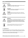
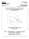
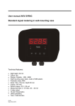
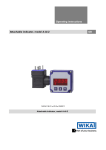
Operating instructions Digital indicator model DI30 14037419 • V2.3 • 02/2012 Digital indicator model DI30 for panel mounting or wall mounting GB GB Operating instructions model DI30 page 1 - 40 © 2010 WIKA Alexander Wiegand SE & Co. KG All rights reserved. WIKA® is a registered trademark in various countries. Prior to starting any work, read the operating instructions! Keep for later use! 2 WIKA operating instructions digital indicator DI30 Contents 1 2 General information ................................................................................4 Safety .......................................................................................................5 2.1 2.2 2.3 2.4 3 4 Intended use........................................................................................5 Personnel qualification.........................................................................7 Special hazards ...................................................................................7 Labelling / Safety marks ......................................................................8 Specifications ..........................................................................................9 Design and function ..............................................................................11 4.1 Short description................................................................................11 4.2 Scope of delivery ...............................................................................12 5 Transport, packaging and storage .......................................................12 5.1 Transport ...........................................................................................12 5.2 Packaging..........................................................................................12 5.3 Storage ..............................................................................................12 6 Commissoning, operation ....................................................................13 6.1 Mounting............................................................................................13 6.2 Electrical connection ..........................................................................16 6.3 Function and operation description ....................................................19 6.4 Programming .....................................................................................22 6.5 Description of the measuring input ....................................................24 6.6 Description of device parameters ......................................................26 6.7 Program number table .......................................................................30 6.8 Default values ....................................................................................32 7 Maintenance and cleaning....................................................................32 7.1 Maintenance ......................................................................................32 7.2 Cleaning ............................................................................................32 8 9 Faults .....................................................................................................33 Dismounting, return and disposal .......................................................34 9.1 Dismounting ......................................................................................34 9.2 Return ...............................................................................................34 9.3 Disposal.............................................................................................35 10 Application example: DI30 and gas cylinder scale GCS-1 .................36 11 Appendix: Declaration of conformity...................................................38 Declarations of conformity can be found online at www.wika.com. WIKA operating instructions digital indicator model DI30 3 1 General information 1 General information The instrument described in the operating instructions has been designed and manufactured using state-of-the-art technology. All components are subject to stringent quality and environmental criteria during production. Our management systems are certified to ISO 9001. These operating instructions contain important information on handling the instrument. Working safely requires that all safety instructions and work instructions are observed. Observe the relevant local accident prevention regulations and general safety regulations for the instrument's range of use. The operating instructions are part of the instrument and must be kept in the immediate vicinity of the instrument and readily accessible to skilled personnel at any time. Skilled personnel must have carefully read and understood the operating instructions, prior to beginning any work. The manufacturer's liability is void in the case of any damage caused by using the product contrary to its intended use, non-compliance with these operating instructions, assignment of insufficiently qualified skilled personnel or unauthorised modifications to the instrument. The general terms and conditions, contained in the sales documentation, shall apply. Subject to technical modifications. Further information: - Internet address: - Relevant data sheet: - Application consultant: 4 www.wika.de / www.wika.com AC 80.05 Tel.: (+49) 9372/132-0 Fax: (+49) 9372/132-406 E-Mail: [email protected] WIKA operating instructions digital indicator DI30 2 Safety Explanation of symbols WARNING! ... indicates a potentially dangerous situation that can result in serious injury or death, if not avoided. Information ... points out useful tips, recommendations and information for efficient and trouble-free operation. DANGER! ...identifies hazards caused by electric power. Should the safety instructions not be observed, there is a risk of serious or fatal injury. 2 Safety WARNING! Before installation, commissioning and operation, ensure that the appropriate instrument has been selected in terms of measuring range, design and specific measuring conditions. Non-observance can result in serious injury and/or damage to equipment. Further important safety instructions can be found in the individual chapters of these operating instructions. 2.1 Intended use The DI30 is designed for the evaluation and display measuring transmitter signals. With the alarm outputs, it is possible to perform simple control tasks. The instrument has been designed and built solely for the intended use described here, and may only be used accordingly. WIKA operating instructions digital indicator model DI30 5 2 Safety Please read the following safety advice and the assembly before installation and keep it for future reference. If the instrument is transported from a cold into a warm environment, the formation of condensation may result in the instrument malfunctioning. Before putting it back into operation, wait for the instrument temperature and the room temperature to equalise. Notes on installation There must be no magnetic or electric fields in the vicinity of the device, e.g. due to transformers, mobile phones or electrostatic discharge. Do not install inductive consumers (relays, solenoid valves etc.) near the device and suppress any interference with the aid of RC spark extinguishing combinations or free-wheeling diodes. Keep input, output and supply lines separate from one another and do not lay them parallel with each other. Position “go” and “return lines” next to one another. Where possible use twisted pair. So, you receive best measuring results. Screen off and twist sensor lines. Do not lay current-carrying lines in the vicinity. Connect the screening on one side on a suitable potential equaliser (normally signal ground). The device is not suitable for installation in areas where there is a risk of explosion. Any electrical connection deviating from the connection diagram can endanger human life and/or can destroy the equipment. The terminal area of the devices is part of the service. Here electrostatic discharge needs to be avoided. Attention! High voltages can cause dangerous body currents. Galvanic insulated potentials within one complex need to be placed on a appropriate point (normally earth or machines ground). So, a lower disturbance sensibility against impacted energy can be reached and dangerous potentials, that can occur on long lines or due to faulty wiring, can be avoided. The fuse rating of the supply voltage should not exceed a value of 1A N.B. fuse. The manufacturer shall not be liable for claims of any type based on operation contrary to the intended use. 6 WIKA operating instructions digital indicator DI30 2 Safety 2.2 Personnel qualification WARNING! Risk of injury should qualification be insufficient! Improper handling can result in considerable injury and damage to equipment. The activities described in these operating instructions may only be carried out by skilled personnel who have the qualifications described below. Keep unqualified personnel away from hazardous areas. Skilled electrical personnel Skilled electrical personnel are understood to be personnel who, based on their technical training, knowledge of measurement and control technology and on their experience and knowledge of country-specific regulations, current standards and directives, are capable of carrying out work on electrical systems and independently recognising and avoiding potential hazards. The skilled electrical personnel have been specifically trained for the work environment they are working in and know the relevant standards and regulations. The skilled electrical personnel must comply with current legal accident prevention regulations. 2.3 Special hazards DANGER! Danger of death caused by electric current. Upon contact with live parts, there is a direct danger of death. Electrical instruments may only be installed and mounted by skilled electrical personnel. Operation using a defective power supply unit (e.g. short circuit from the mains voltage to the output voltage) can result in life-threatening voltages at the instrument! WARNING! Do NOT use this product as safety or emergency stopping device, or in any other application where failure of the product could result in personal injury or material damage. Failure to comply with these instructions could result in death or serious injury and material damage. WIKA operating instructions digital indicator model DI30 7 2 Safety 2.4 Labelling / Safety marks Product label 1: power supply 2: order code 3: serial no. 4: CE mark 5: product name 6: connection diagram Explanation of symbols Before mounting and commissioning the instrument, ensure you read the operating instructions! CE, Communauté Européenne Instruments bearing this mark comply with the relevant European directives. 8 WIKA operating instructions digital indicator DI30 3 Specifications 3 Specifications Specifications Display Principle Character size Indication range Indication time Memory Input Number and type Input signal Input configuration Accuracy Temperature drift Measuring principle Resolution Measuring time Transmitter supply Power supply Power consumption Electrical connection Alarm output Number and type Contact Switching cycles 7-Segment-LED, red, 4 digit 20 mm -999 … +9999 0.1….10 sec EEPROM (Parameter memory, Data storage > 20 years) 1 input for standard signals 4...20 mA, input resistance ≤ 100 Ω or 0...20 mA, input resistance ≤ 100 Ω or DC 0...5 V, input resistance ≥ 150 kΩ or DC 0...10 V, input resistance ≥ 150 kΩ selectable via terminal configuration and programming ± 0.1 % of the measuring span ± 1 Digit All measuring inputs 50 ppm/K Voltage/Frequency converter approx. 20 bit, (at measuring time 1second) 0.1….10 sec DC 24 V, max. 50 mA, galvanically isolated AC 230 V, 50/60 Hz, ± 10 % {AC 115 V, 50/60 Hz, ± 10 %} Max. 8 VA removable screw terminals Line cross section up to 2.5 mm2 2 independent switching contacts (relays), freely adjustable load: AC 230 V, 5 A (resistive load) DC 30 V, 5 A (resistive load) 0,5 * 105 at max. contact rating 5 * 106 mechanically Separation as per DIN EN 50178 Characteristics as per DIN EN 60255 WIKA operating instructions digital indicator model DI30 9 3 Specifications Case Material Ingress protection Dimensions Mounting clearance Weight Mounting {Wall mounting enclosure} Material Ingress protection Dimensions Cable gland Mounting Aluminium, black Front: IP 54, Rear: IP 00 96 x 96 x76 mm (w x h x d) including terminals horizontal 120 mm / vertical 120 mm (recommended) Approx. 530 g sliding fasteners, fixed via screws, for panel thicknesses from 1 mm to 10 mm ABS, black, cable gland IP 65 160 x 130 x 60 mm (w x h x d) Cable thickness: 4.0...8.0 mm Fixing holes for screws Permissible ambient conditions Operating temperature 0…60 °C Storage temperature -20…80 °C Humidity 0…75 % relative humidity, non-condensing CE conformity EMC directive Low voltage directive 2004/108/EC, EN 61326-1 Emission (Group 1, Class B) and Immunity (industrial locations) 2006/95/EC, EN 61010-1 { } Items in curved brackets are optional extras for additional price. For further specifications see WIKA data sheet AC 80.05 and the order documentation. 10 WIKA operating instructions digital indicator DI30 4 Design and function Operating elements 1: Program key 2: DOWN key 3: UP key 4: Zero key 5: 7 segment display 6 +7: LEDs for displaying the alarm contacts 4 Design and function 4.1 Short description With the digital indicator DI30 standard signals DC 0/4…20 mA or DC 0…5/10 V can be measured. The 4 digit display shows the measurements or the scaled value of the measurement. During programming the display is used to indicate the set values and the user prompts. Two relays (alarm outputs 1 and 2) are available to monitor threshold values, the status of which is displayed via two separate LED on the front. The integrated DC 24 V transmitter supply is used to supply connected sensors. WIKA operating instructions digital indicator model DI30 11 5 Transport, packaging and storage 4.2 Scope of delivery The scope of delivery is: Indicator for panel mounting: Indicator 2 fixing elements Seal Operating instructions Indicator for wall mounting: Indicator Operating instructions Cross-check scope of delivery with delivery note. 5 Transport, packaging and storage 5.1 Transport Check instrument for any damage that may have been caused by transport. Obvious damage must be reported immediately. 5.2 Packaging Do not remove packaging until just before mounting. Keep the packaging as it will provide optimum protection during transport (e.g. change in installation site, sending for repair). 5.3 Storage Permissible conditions at the place of storage: Storage temperature: -20 ... +80 °C Humidity: 0 ... 75 % relative humidity (no condensation) Avoid exposure to the following factors: 12 Direct sunlight or proximity to hot objects Mechanical vibration, mechanical shock (putting it down hard) Soot, vapour, dust and corrosive gases Potentially explosive environments, flammable atmospheres WIKA operating instructions digital indicator DI30 6 Commissoning, operation Store the instrument in its original packaging in a location that fulfils the conditions listed above. If the original packaging is not available, pack and store the instrument as described below: 1. Wrap the instrument in an antistatic plastic film. 2. Place the instrument, along with shock-absorbent material, in the packaging. 3. If stored for a prolonged period of time (more than 30 days), place a bag, containing a desiccant, inside the packaging. WARNING! Before storing the instrument (following operation), remove any residual media. This is of particular importance if the medium is hazardous to health, e.g. caustic, toxic, carcinogenic, radioactive, etc. 6 Commissoning, operation Please read the safety instructions and installation instructions in chapter 2 before installation and keep this user manual for future reference. 6.1 Mounting Indicator for panel mounting: Before assembly a cut-out must be made to accommodate the device. The sizes and tolerances are given in the technical data. On front of the DI30 are the operating and display elements. On the sides are the fixing elements to mount the device in the panel. On the back are the terminals for all the electrical connections. A gasket is inserted between the contact surface of the front collar and the control panel. WIKA operating instructions digital indicator model DI30 13 6 Commissoning, operation 1. After removing the fixing elements, insert the device. 2. Check the seal to make sure it fits securely. 3. Click the fixing elements back into place and tighten the clamping screws by hand. Then use a screwdriver to tighten them another half a turn. CAUTION! The torque should not exceed 0.1 Nm! Indicator for wall mounting: The wall-type housing consists of an upper part and a lower part. A suitable seal has been inserted in the lower part to achieve protection IP 66. In the upper part is the DI30 with its operating and display elements. On the back are the terminals for all the electrical connections. 14 WIKA operating instructions digital indicator DI30 6 Commissoning, operation 1. The cover flaps have to be opened on the right and left side. Loose the four fixing screws, which connect the upper and lower part of the enclosure, with a screw driver. Remove the upper part. 2. Fasten the enclosure to the wall. 3. Connecting cables have to be fed into the enclosure via the PG screws. 4. After connection the upper part of DI30 will be placed on the lower part. Using the four fixing screws, screw the upper part to the lower part. Be sure that the screws are completely tightened in order to attain ingress protection IP66. Finally close the cover flaps again.. Screws for wall mounting are not part of scope of delivery. Please use screws according to the material of the wall, where you want to install the enclosure. WIKA operating instructions digital indicator model DI30 15 6 Commissoning, operation 6.2 Electrical connection All the necessary signals for operation are connected to the rear terminals. The connecting terminals are designed as removable screw-type terminals with a grid pitch of 5.08 mm. This makes it possible to connect wires of up to 2.5 mm². 6.2.1 Terminal configuration 9-pole connector strip On the 9-pole connector strip with terminals 1 to 9, the power supply (supply voltage) of the digital indicator and the two relay outlets of the alarm outputs are connected. Power supply 4 N Relay 2 (A2) 1 2 Com Normally open 5 PE 3 Normally closed 6 L Relay 1 (A1) 7 8 Com Normally open 9 Normally closed 5-pole connector strip On the 5-pole connector strip with terminals 10 to 14 the input signal and the transmitter supply are connected. Measuring input for standard signals The input signal is connected to terminals 10 to 12. The DI30 has a voltage input and a current input, to which most conventional sensors with a standard signal output can be connected. The measuring input is galvanically isolated from the power supply (supply voltage) and the transmitter supply. Input for standard signals 10 11 12 U (+) I (+) 16 U (-) I (-) Sensor signal 0…5 V 0…10 V 0…20 mA 4…20 mA Measuring range -12…+12 V -24…+24 mA WIKA operating instructions digital indicator DI30 6 Commissoning, operation Transmitter supply The DC 24 V transmitter supply is available at terminals 13 and 14. The transmitter supply is galvanic insulated from the measuring input. Current loop sensors (2-wire) and 3-wire and 4-wire sensors can be operated via the transmitter supply as long as their current consumption is not higher than 50 mA (Power consumption < 1.2 VA). Transmitter supply 13 Transmitter supply (-) 14 Transmitter supply (+) 6.2.2 Connection Examples This section gives a few examples of practical connections. a) 4…20 mA signal, 2-wire-transmitter b) 0…20 mA signal, 3-wire-transmitter The voltage drop on the transmitter supply wire is irrelevant, which is why this can also be bridged directly on the indicator. WIKA operating instructions digital indicator model DI30 17 6 Commissoning, operation c) 0…5 V/0…10 V signal, 3-wire-transmitter The ground is bridged via the sensor, which eliminates the measuring error through the drop in voltage on the transmitter supply wires. 18 WIKA operating instructions digital indicator DI30 6 Commissoning, operation 6.3 Function and operation description 6.3.1 Operation The DI30 has 4 keys ([P], [], [], [O]), with which you can parameterise and call up various functions during operation. Additionally it has a 4-digit 7-segment display and two LEDs for displaying the alarm contacts. 1 Name Program key [P] 2 DOWN key [▼] 3 UP key [▲] 4 5 Zero key [O] 7-segment display 6+7 Alarm displays Description With the program key, you can call up the programming mode or perform various functions in the programming mode. With the DOWN (decrease) key, you can call up the MIN memory or alter parameters in the programming mode. With the UP (increase) key, you can call up the MAX memory or alter parameters in the programming mode. Zero key for TARA and HOLD function In the 7-segment display measuring values are displayed, respectively, during programming, the program numbers or parameters are displayed. The alarm display indicates the state of the relays of the alarm outputs. If a relay is switched, the LED lights up.. WIKA operating instructions digital indicator model DI30 19 6 Commissoning, operation 6.3.2 Switching on Before switching on you have to check all the electrical connections to make sure they are correct. On completion of the installation, the device can be switched on by applying the power supply. During the switching-on process a segment test is performed for approx. 1 second, whereby all LEDs on the front (including alarm LEDs) are triggered. After this, the type of software is indicated for approx. 1 second and then, also for 1 second, the software version. After the starting procedure, the unit changes to operation/display mode. 6.3.3 General functions MIN/MAX Memory The measured minimum and maximum values are saved in a volatile memory in the unit and get lost when the unit is switched off. You can call up the contents of the memory by pushing (less than 1 second) the [▲] or [▼] key. The relevant value is indicated for approx. 7 seconds. By briefly pressing the same key again, you will return immediately to the display mode. [▲] Display of the MAX value [▼] Display of the MIN value You can erase the value shown in the display by simultaneously operating the [▲] & [▼] keys. The erasure is acknowledged by horizontal bars. The content of the memory is lost when the unit is switched off. Overflow and Underflow An overflow of the display is indicated by horizontal bars at the top of the 7segment display „ ¯ ¯ ¯ ¯ “. An underflow of the display is indicated by horizontal bars at the bottom of the 7 segment display „ _ _ _ _ “ 20 WIKA operating instructions digital indicator DI30 6 Commissoning, operation 6.3.4 Description of the alarm outputs With the aid of the LEDs below the 7-segment display, you can view the switching state of the alarm outputs. An active relay is indicated by the relevant LED lighting up. Working principle The alarm outputs have the following properties with regard to their switching properties: Parameter Alarm output Threshold Hysteresis Operating principle Switch-on delay Switch-off delay Description Deactivated, activated Threshold value for switchover Width of the window between the switch thresholds Active above SP value / active below SP value Time between reaching the threshold and the resultant switching on of the relay Time between reaching the threshold and the resultant switching off of the relay Active above threshold The alarm output is off below the threshold and switched on when reaching the threshold. Active below threshold The alarm output is on below the threshold and switched off on reaching the threshold. WIKA operating instructions digital indicator model DI30 21 6 Commissoning, operation Switch-on delay The relay is on e.g. 10 seconds after reaching the threshold. Briefly exceeding the threshold does not lead to the relay being switched on. The switch-off delay functions in a similar manner, in other words it keeps the alarm output switched on until the parameterised time has elapsed. Optical response: display flashing The switching on of one or more alarm outputs can also be set to trigger a flashing of the display, to enhance the optical response. 6.4 Programming The display shows the program numbers (PN) right-aligned, as a 3-digit number with a P at the front. Display of e.g. program number 0 Programming Procedure The entire programming of the DI30 is done by the steps described below. Change to the programming mode Pushing the [P] key changes to programming mode. The unit goes to the lowest available program number. When the programming lock is activated, the key must be pressed for at least 1 second. Example: Change to programming mode by pushing key [P]. The first released program number (PN) appears, in this case PN0 22 WIKA operating instructions digital indicator DI30 6 Commissoning, operation Changing to other program numbers To change between individual program numbers, hold the [P] key down and press the [] key for changing to a higher program number or the [] key for changing to a lower number. By keeping the keys pushed, e.g. [P] & [], the display will begin, after approx. 1 second, to automatically run through the program numbers. Example: Under PN0 a 1 is parameterized. Hold the [P] key down and press the [] key once. PN1 appears in the display. Under this parameter, the final value of input can be changed. Change to the parameter Once the program number appears in the display, you can press the [] or [] key to get to the parameters set for this program number. The currently stored parameters are displayed. Example: By pressing the [] or [] key, the currently stored value for PN1 appears in the display. In this case it is 75.64. Changing a parameter After changing to the parameter, the lowest digit of the respective parameter flashes on the display. The value can be changed with the [] or [] key. To move to the next digit, the [P] key must be briefly pressed. Once the highest digit has been set and confirmed with [P], the lowest digit will begin to flash again. Example: The 4 is flashing; this is the lowest value digit and, by flashing, it is asking for a figure to be entered. In our example, the value is to be changed from 75.64 to 75.00. You can change the value by changing the figure from 4 to 0 using the [] or [] key. To move to the next digit, the [P] key must be briefly pressed. The 6 begins flashing. Change the value from 6 to 0 using the [] or [] key. The 5 and the 7 need no change. WIKA operating instructions digital indicator model DI30 23 6 Commissoning, operation Saving parameters All parameters must be acknowledged by the user by pressing the [P] key for one second. The changed parameters are then taken over as the current operating parameters and saved in the EEPROM. This is confirmed by horizontal bars lighting up in the display. Example: Save the parameters by pressing [P] for one second. All the newly entered data are confirmed by the unit. If no confirmation is received, the relevant parameters have not been saved. Example: You receive confirmation from the unit that the changes have been saved through the appearance of horizontal bars in the middle segments. Change to the operating mode If no key is pressed in programming mode for approx. 7 seconds, the unit automatically returns to operating mode. 6.5 Description of the measuring input The DI30 is equipped with a measuring input for standard signals that enables standardised signals (e.g. 4 … 20 mA) from all kinds of different measuring transmitters on the market to be measured directly. Factory calibration For this, various sensor values for 0 … 10 V, 0 … 5 V, 0 … 20 mA and 4 … 20 mA are stored in the unit and can be called up via the parameter PN0. They are called factory calibrations, because the data were established during production and are saved permanently in the unit. It means that a preadjusted transmitter can be operated directly with the indicator, without any need to previously connect the signal to be measured to the indicator. The indicator can be scaled freely according to the physical dimension to be measured. Sensor calibration If, on the other hand, the sensor has not been pre-calibrated, the indicator can be adjusted and calibrated direct via the measurement together with the sensor path. This can be selected via the parameter PN0 = 0 and is consequently called sensor calibration. 24 WIKA operating instructions digital indicator DI30 6 Commissoning, operation Sensor linearisation In addition, non-linear sensors can be linearised with the aid of a characteristic line that can be saved in the indicator. This is described with the following example: The sensor signal must be parameterised in a strictly monotonously manner, i.e. every new calibration point (e.g. PN104) must have a higher input signal than the previous one (e.g. PN103) so that it is taken over by the indicator. Otherwise, no confirmation will be shown. On the other hand, the relevant indication values do not need to increase constantly. They can also fall or alternate between rising and falling. Example: Linearisation of a pressure transmitter (0...100 mbar) with output 0…20 mA. To program e.g. 5 additional calibration points, “5” must be entered under PN100. Subsequently, for each of the calibration points, the voltage/current must be applied to the unit and the respective indication value programmed under the following program numbers PN101 - PN105. The indicated value before correction can be either calculated from the known characteristic line of the transmitter or determined empirically. The non-linear range is between 0 ... 75 mbar. For calibration point 101, this means: A pressure of 15 mbar, the transmitter delivers 3.3 mbar instead of the ideal value of 3.0 mbar. Since 20 mA in the display corresponds to 100.0 mbar, 3.3 mA in the display corresponds to 16.5 mA before the correction. Setpoint (PN) 2 101 102 103 104 105 1 Pressure [mbar] 0 15 30 40 60 75 100 Output Indication transmitter before [mA] correction (IN) 0.5 2.5 3.3 16.5 6.2 31.0 9.2 46.0 11.4 57.0 14.7 73.5 20.0 100.0 WIKA operating instructions digital indicator model DI30 Desired indication (OUT) 0.0 15.0 30.0 40.0 60.0 75.0 100.0 25 6 Commissoning, operation 6.6 Description of device parameters The DI30 has a number of unit parameters with which the function of the indicator can be adjusted to the relevant measuring tasks. Because of the large number of these settings and the limited possibility of displaying them on the 7-segment display, the parameters have been given consecutive numbers. (see chapter “6.7 Program Number Table”) PN0: Measuring input One of the aspects in the basic configuration is the desired measuring input, which consists of the terminal selection and the relevant factory or sensor calibration. PN1 and PN2: Scaling The two program numbers 1 and 2 are used to scale the indication. With these two parameters the end value and start value are parameterised. If sensor calibration has been selected via PN0 = 0, then the current for the relevant sensor signal must be applied during programming. Otherwise, a simple allocation of the selected input configuration will be made. For example, at PN0 = 3, which corresponds to a standard signal input 0 … 10 V, the value saved under PN1 will be indicated at 10 V, and the value saved under PN2 will be indicated at 0 V. PN3: Decimal point By changing this parameter the number of places shown after the decimal point in the display is changed. This parameter has no influence on the scaling of the indication value, only on the position of the decimal point in the display. PN5: Offset shift With this parameter it is possible to carry out a parallel shift of the parameterised characteristic line. This may be necessary, if for example a pressure transmitter ages over the course of time, giving rise to a shift in the zero point. With the parallel shift the transmitter can be adjusted back to the zero point. Another application is to parameterise a certain tank level to zero and have any deviation from this level displayed. PN10: Zero point suppression Via the zero point suppression, an indication value window can be defined as zero. This means, for example, that at PN10 = 10, all indication values between –10 … +10 are shown in the display as zero. This function is intended to produce a reliable zero indication at high display resolution and low sensor accuracy around zero. This could be, for example, the rpm of an engine for which a zero would be expected in the display when standing still. 26 WIKA operating instructions digital indicator DI30 6 Commissoning, operation PN13: Indication time The indication time is the interval at which the display is updated. The longer the time between two indication cycles, the more calm the display. As a rule, the eye perceives the indication time of 1 sec. as very pleasant. If the adjusted indication time is longer than the adjusted measuring time (PN14), no averaging of the detected measuring values during the display time takes place. The display will be always refreshed with the newest detected measuring value. PN14: Measuring time The measuring time corresponds to the conversion time of the A/D conversion, which determines the response time of the alarm outputs. The longer the conversion time the smaller the influence of disturbances and the higher the resolution of the measured signal. PN50 to PN52: Security setting, user level With the parameters in the security settings, access to the program numbers is regulated through the setting of various user levels. The user levels divide the access into various levels. The user is only given access to the settings authorised by the system operator, such as the setting of thresholds. The lower the figure for the user level given in PN52, the lower is the security level of the unit parameters against user intervention. (●: available function at the selected userlevel) Userlevel (PN 52 =) Access to: Locking code / user level Measuring input parameters Tara / Hold Linearization parameters for measuring input Parameters of the alarm outputs Hysteresis of the alarm outputs Thresholds of the alarm outputs Access code Serial number 0 1 2 3 4 5 6 7 8 PN: 51, 52 0 ... 3, 5, 10, 13, 14 54 100 ... 110 ● ● ● ● ● ● ● ● ● ● 59, 60, 63 … 65,70, 73 … 75 62, 72 61, 71 50 200 ● ● ● ● ● ● ● ● ● ● ● ● ● ● ● ● ● ● ● ● ● ● ● ● ● ● ● ● ● ● ● ● ● ● ● ● The user levels 1, 3 and 7 are reserved user levels at which access to the higher numbered user level is active. The parameterised user level PN52 is active as long as the locking code PN51 and the access code PN50 are different. On delivery of the DI30 both parameters are set to 0000, so that the programming lock is deactivated. WIKA operating instructions digital indicator model DI30 27 6 Commissoning, operation To activate the set user level, you must enter a 4-digit number under PN51 as a “locking code” and confirm it by pressing the [P] key for approx. 1 second. On changing to programming mode, the unit jumps to the first authorised program number. If user level PN52 = 3, then, for example, the parameters of the alarm outputs can be changed, but changing the parameter of the measuring input (PN0) is not possible at this user level. In order to obtain access to all program numbers later (equivalent to user level 0), you have to enter under PN50 the same code you entered before under PN51. You must then acknowledge this by pressing the [P] key for approx. 1 s. After this you have access to all program numbers. Information If the locking code becomes lost, the unit can be set to the default value 0000 at the manufacturer's without any data loss. PN54: Allocation of functions of the zero key By pushing of the zero key [O] functions like e.g. TARA and HOLD can be actuated or an offset shift can be preset. By allocation of TARA the key needs to be pushed for at least 1 second. The device confirms the function by showing „0000“ in the display. With activated offset shift, the value in PN5 will be added to the initial value directly by pushing the key. A display hold can only be actuated for approx. 20 seconds. By pushing the zero key again one turns back into the current measurement directly. During HOLD phase the display flashes. PN59: Display flashing By activating the display flashing, various alarm states can be optically reinforced. The trigger for the display flashing can be freely assigned to the setpoint outputs. PN60 to PN75: Alarm outputs The behaviour of the alarm outputs can be influenced via various program numbers. The data refer to the scaled measurement and are updated with the set measuring time. A description of the various parameters is given in chapter “6.3.4 Description of alarm outputs”. 28 WIKA operating instructions digital indicator DI30 6 Commissoning, operation PN100 to PN110: Linearisation Through linearisation, the user has the possibility to linearise a non-linear sensor signal. A detailed description can be found in the chapter on Sensor linearisation. Under PN100, the desired number of additional set points can be released. Only after changing the number are they accessible via the configuration PN101 to max. PN110. If PN100 = 0, then no PN101 will be displayed. To monitor the desired linearisation, all the set points should first be parameterised, otherwise there may be deviations from the desired value in the display! PN200: Serial number Under PN200 the 4-digit serial number can be called up, that allows allocation to the production process and the manufacturing procedure. This parameter can only be viewed. WIKA operating instructions digital indicator model DI30 29 6 Commissoning, operation 6.7 Program number table The program table lists all the program numbers (PN) with their function, range of values, default values and user level. PN Function Range of value 0 Measuring input Current, Voltage: 0 = Sensor calibration 1 = 0 ... 20 mA 2 = 4 ... 20 mA 3 = 0 ... 10 V 4 = 0 ... 5 V -999 ... 9999 -999 ... 9999 0=0 1 = 0.0 2 = 0.00 3 = 0.000 -999 … 9999 Parameters 1 to 4 make use of the factory calibration. 1 2 3 Scaling final value Scaling starting value Number of decimal places 5 Offset shift on display value 10 Zero point suppression General settings 13 Indication time 14 Measuring time Security settings 50 Access code 51 Locking code 52 User level Function of the zero key 54 Actuator via zero key Flashing of the LED-display 59 Display flashing (approx. 0.5 seconds) No flashing Flashes at alarm 1 Flashes at alarm 2 Flashes at alarm 1 and 2 30 Default 2 User level 2 1000 2 0 2 0 2 0 2 0 … 999 0 2 0.1 ... 10.0 0.01 ... 10.0 1,0 0.1 2 2 0000 ... 9999 0000 ... 9999 1 ... 8 0000 0000 8 8 0 0 0 = deactivated 1 = TARA 2 = Offset shift 3 = HOLD 0 2 0 4 0 = no flashing 1 = flashes at 1 2 = flashes at 2 3 = flashes at 1 and 2 WIKA operating instructions digital indicator DI30 6 Commissoning, operation PN Function Alarm output 1 60 Alarm output 1 61 62 63 64 65 Threshold Hysteresis Active below / above threshold value Switch delay Delay type Alarm output 2 70 Alarm output 2 71 72 73 74 75 Threshold Hysteresis Active below / above threshold value Switch delay Delay type Linearisation 100 Number of additional setpoints 101... Setpoints 1 ... 10 110 Information 200 Serial number Range of value Default User level 0 = deactivated 1 = activated -999 ... 9999 1 ... 9999 0 = active below 1 = active above 0 … 1000 seconds 0 = none 1 = switch-on delay 2 = switch-off delay 3 = switch-on/-off delay 1 4 1000 1 1 6 5 4 1 0 4 4 0 = deactivated 1 = activated -999 ... 9999 1 ... 9999 0 = active below 1 = active above 0 … 1000 seconds 0 = none 1 = switch-on delay 2 = switch-off delay 3 = switch-on/-off delay 1 4 1000 1 1 6 5 4 1 0 4 4 0 ... 10 0 2 -999 ... 9999 0 ... 9999 WIKA operating instructions digital indicator model DI30 2 0 8 31 7 Maintenance and cleaning 6.8 Default values Reset to default values To return the unit to a defined basic state, a reset can be carried out to the default values. The following procedure should be used: Switch off the power supply Press button [P] Switch on the power supply and press [P] for further approx. 2 seconds until „- - - -“ is shown in the display. With reset, the default values of the program table are loaded and used for subsequent operation. This puts the unit back to the state in which it was supplied. Caution! This is only possible when the programming lock PN50 allows access to all PNs or “HELP” is shown in the display. Caution! All application-related data are lost 7 Maintenance and cleaning 7.1 Maintenance This instrument is maintenance-free. Repairs must only be carried out by the manufacturer. 7.2 Cleaning CAUTION! Before cleaning, correctly disconnect the instrument from the mains. Clean the instrument with a moist cloth. Electrical connections must not come into contact with moisture. For information on returning the instrument see chapter "9.2 Return". 32 WIKA operating instructions digital indicator DI30 8 Faults 8 Faults Fault The unit permanently indicates overflow „ ¯ ¯ ¯ ¯ “ (4 bars in the upper part of the display) The unit permanently indicates underflow „ _ _ _ _ “. (4 bars in the lower part of the display) The device shows “HELP” in the 7segment display. Program numbers for parameterising the input are not available. „Err1“ lights up in the 7-segment display Solution The input has a very high measurement, check the measuring circuit. The input has a very low measurement, check the measuring circuit. The unit has found an error in the configuration memory. Perform a reset on the default values and reconfigure the unit according to your application. The program lock is set to a user level that does not permit access. This error can only be eliminated by the manufacturer. Please return to the manufacturer. CAUTION! If faults cannot be eliminated by means of the measures listed above, the instrument must be shut down immediately, and it must be ensured that pressure and/or signal are no longer present, and it must be prevented from being inadvertently put back into service. In this case, contact the manufacturer. If a return is needed, please follow the instructions given in chapter "9.2 Return". WIKA operating instructions digital indicator model DI30 33 9 Dismounting, return and disposal 9 Dismounting, return and disposal WARNING! Residual media in dismounted instruments can result in a risk to persons, the environment and equipment. Take sufficient precautionary measures. 9.1 Dismounting To dismount the instrument, do the following steps: Indicator for panel mounting: 1. Open the clamping screws and remove the fixing elements. 2. Remove the instrument and seal from panel cutout. Indicator for wall mounting: For dismounting the indicator open the four fastening screws of the enclosure and remove it. 9.2 Return WARNING! Strictly observe when shipping the instrument: All instruments delivered to WIKA must be free from any kind of hazardous substances (acids, bases, solutions, etc.). When returning the instrument, use the original packaging or a suitable transport package. Enclose the completed return form with the instrument. The return form is available on the internet: www.wika.de / Service / Return 34 WIKA operating instructions digital indicator DI30 9 Dismounting, return and disposal 9.3 Disposal Incorrect disposal can put the environment at risk. Dispose of instrument components and packaging materials in an environmentally compatible way and in accordance with the country-specific waste disposal regulations. WIKA operating instructions digital indicator model DI30 35 10 Application example: DI30 and gas cylinder scale GCS-1 10 Application example: DI30 and gas cylinder scale GCS-1 Adjustment hints for digital indicator DI30 in combination with gas cylinder scale GCS-1 In the following there is an example explaining the setting parameters of DI30. With the help of the gas cylinder scale GCS-1 the level of a gas cylinder has to be calculated. This value shall be displayed on DI30. At a certain level, an alarm will be triggered. Please look at the type label for relevant datas: Measuring range: 0…136.1 kg Output signal: 4…20 mA, 2-wire Additionally the TARA weight of the empty gas cylinder, which is printed on the outside of the cylinder, eg. TARA=20,0 kg. Connection example Measurement of current signal (4…20 mA, 2-wire) using the integrated transmitter supply: 36 WIKA operating instructions digital indicator DI30 10 Application example: DI30 and gas cylinder scale GCS-1 Adjustment With the program numbers 0, 1, 2 and 3 the indicator is configured according to the connected scale. For program number 5 „Offset shift on display value“ the TARA-value has to be entered as negative value. The weight of the scale is subtracted automatically, only the actual weight of the filling will be shown in the display. PN 0 1 2 3 5 Function Input signal Scaling final value (value, which is shown at 20 mA; Corresponds to the full measuring range of GCS-1) Scaling starting value (value which is shown at 4 mA; Corresponds to the beginning of the measuring range) Number of decimal places after separator Offset shift on display value (negative TARA value, which is printed on the gas cylinder) Set values 2 = 4 ... 20 mA 1361 0 1 = 0,0 -20,0 If an alarm should be activated at an certain filling level (eg. 5 kg) the alarm output (eg. A1) has to be configured accordingly: Alarm output 1 60 Alarm output 1 61 Threshold 1 = activated 5 Program numbers P62…P65 have to be set accordingly to your technical conditions. WIKA operating instructions digital indicator model DI30 37 11 Appendix: Declaration of conformity 11 Appendix: Declaration of conformity 38 WIKA operating instructions digital indicator DI30 11 Appendix: Declaration of conformity WIKA operating instructions digital indicator model DI30 39 WIKA global WIKA subsidiaries worldwide can be found online at www.wika.com. WIKA Alexander Wiegand SE & Co. KG Alexander-Wiegand-Straße 30 63911 Klingenberg • Germany Tel. (+49) 9372/132-0 Fax (+49) 9372/132-406 E-Mail [email protected] www.wika.de 40 WIKA operating instructions digital indicator DI30