Download User Manual - R. Barot & Co.
Transcript
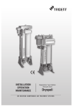
Installation,
Operation,
Maintenance
Series DP
WE REDEFINE COMPRESSED AIR TREATMENT SYSTEMS
Contents
1.
Introduction
3
1.1
1.2
1.3
1.4
1.5
1.6
Design
Specifications
Description
Adsorbant Material
Operating Principles
Safety
3
3
3
4
4
4
2.
Installation
5
2.1
2.2
2.3
2.4
Storage
Installation site and connections
Electrical connections
Running the Installation
5
5
6
6
3.
Operation
7
3.1
3.2
3.3
3.4
Operator
Control panel
Operating cycle time
How to stop the dryer
7
7
7
8
4.
Maintenance
8
4.1
4.2
Changing the pre, oil and after filter element
Changing the desiccant
9
9
5.
Changing the desiccant
9
6.
Repair work
6.1
6.2
6.3
6.4
6.5
6.6
6.7
LEDs not glowing
Tower status led not changing
LEDs status changes but tower not switching
No purging
Continuous purging at tower 1
High purge loss
High pressure drop across dryer
7.
Commissioning Report
10
This Document may be modified without notice
reproduction, even partial, forbidden without written Authentication
INSTRUCTION MANUAL -
DP Series
READ THIS MANUAL CAREFULLY
BEFORE INSTALLING OR OPERATING THE EQUIPMENT
!
These symbols warn you of any dangers and the measures to be taken to
prevent them.
The most important points for the correct operation of your dryer are printed in bold type.
1. Introduction
DP series is a heatless adsorption air dryer range especially made for higher compressed air flow
treatment. Rigid and easy to maintain, each dryer is equipped with a pre-filter 25micron to protect the
desiccant from the variety of air-compressed pollutant and with after filters to avoid fine desiccant
powders at the outlet.
1.1 Design
DP series heat-free regenerating adsorption dryers make it possible to eliminate any water vapour
remaining in the compressed air at the outlet of the compressor + final condenser assembly. The dryers
have been designed under nominal standard conditions in order to obtain a dew point at atmospheric
pressure of - 40oC.
1.2 Specifications
Operational Data
Inlet Air
Condition
:
Temperature
Humidity
:
:
Free of dirt, oil and corrosive
Substances
Max + 40oC
Saturated at specified
condition
Outlet Air
Pre Filter rating
After Filter rating
:
:
25 Microns
5 Microns
Oil Adsrober rating
Atm. Dew point
:
:
1 PPM
Better than -40oC
Control Voltage
:
230 VAC / 1Ø / 50 Hz
2
Reference : Manual Version 2
Constructional Data
Model
End
Connections
DP 72
¾"BSP
DP 96 to
DP 288
1" BSP
DP 384
1½" BSP
DP 480 to
DP 960
2" NB ANSI B
16.5 Cl.150
DP 1440 to
DP 1920
3" NB ANSI B
16.5 Cl.150
1.3 Description
The dryer consists of :
z
z
z
z
z
z
z
z
z
z
z
z
z
2
1
2
3
2
1
1
3
2
1
1
1
1
Adsorbent towers filled with desiccant
Inlet valve or 2 Nos (above DP1440)
Exhaust valve
solenoid valves
exhaust silencers
regeneration nozzle
electronic control panel
Non return valve or 2 Non return valve (above DP960)
Pressure gauge
3/2 ball valve or 2 3/2 way (above DP 960)
Pre filter with drain valve
oil filter with drain valve
After filter
1.4 Adsorbant material
The desiccant takes the form of highly porous particles with surfaces, which are able to retain (adsorb)
the water vapour present in the compressed air (drying phase) and restore it when the air is at
atmospheric pressure (regeneration phase). The desiccant used is activated alumina (Al2O3).
1.5 Operating Principle
z
z
z
z
z
Moist Air from the compressor enters into the Pre filter through the inlet valve, water and oil
coalesces here. The condensate is drained by Drain valve.
Then it passes through the Oil filter, oil vapour condenses here. The condensate is drained by
the Drain valve.
In the drying tower, Alumina adsorbs the water vapour present in air and drops the dewpoint to
lesser than -40oC.
Fine Alumina fines are removed in the After filter, rating 5 microns.
Clean air is let out through the outlet port.
The two towers operate alternately in the drying and regeneration phases. Regeneration in one tower
results from the expansion to atmospheric pressure of part of the compressed air in the other. Under
nominal conditions (service pressure of 7 bar), 10% of the nominal flow is used for regeneration. The
regeneration phase is shorter than the drying phase in order to allow the regenerated tower to return
This Document may be modified without notice
reproduction, even partial, forbidden without written Authentication
3
INSTRUCTION MANUAL -
DP Series
to service pressure before a new cycle starts. The dryer is equipped with a two pressure gauge in each
tower in order to measure the operating pressure of the tower.
1.6 Safety
!
Pressurised tanks may explode if used improperly. It is therefore essential to
locate any equipment, which contains one or more of such tanks in such a way
that the risks relating to incorrect use are reduced to the absolute minimum.
The person responsible for the stuff who is going to install, operate and maintain the machines described
in this manual must make sure that they have read and understood these instructions.
In particular we draw your attention to the safety procedures which are described in this manual and
which must be scrupulously adhered to. Observing these measures will allow you to install, operate and
maintain your dryer without risk.
DP Series dryers are intended for the drying of compressed air. Under no circumstances should they
be used to dry other gases before Trident has performed a preliminary study and provided special
instructions.
The desiccants used are not noxious. However, they may cause respiratory problems if they are inhaled
in dust form. The use of a dust mask is sufficient to protect personnel. If dispersed in the environment,
desiccants may represent a source of pollution the consequences of which are uncontrollable. By the
end of its lifetime, the desiccant will have accumulated all the pollutants present in the compressed air.
Use a non-polluting method of disposal.
2. Installation
!
Various risks (crushing, explosion, projection, noise,…) : The installation
operations described in this chapter should be performed by personnel qualified
in the installation of electro-pneumatic systems. Follow the procedure described
below with care in order to prevent exposing personnel to danger.
2.1 STORAGE
If your dryer is about to be stored during a long time before installation and use, take care to the
following instructions :
z
4
If possible let the dryer in its original packing (In particular products fitted with marine packing
with plastic film and desiccant)
Reference : Manual Version 2
z
Check that air inlet and outlet are correctly blocked in order to protect the desiccant against
humidity and dust.
z
Check that the machine is correctly protected from atmospheric dust or water.
z
Check that the store is frost protected
z
Make sure to archive correctly the attached documents.
2.2 Installation site and connections
1. Install the dryer in a closed clean, dry room protected. Access to the room should be restricted to
personnel qualified in unit maintenance and operation. The room must be adequately ventilated. The
dryer must not be directly exposed to sources of heat. The temperature of the room must not exceed
43°C.
2. Make sure that the dryer is not near any equipment which does not comply with the electromagnetic
compatibility directives and which may degrade dryer operation. There must be a minimum distance
of 1 m between the dryer and any other equipment, which uses electricity.
3. Ensure that the dryer is installed in vertical position.
4. Fix the anchor points if it's necessary.
5. No bypass valve is required since the dryer itself is provided with the bypass system.
6. Connect the compressed air for processing to the dryer inlet (pre-filter connection) with strain-free
ducts.
This Document may be modified without notice
reproduction, even partial, forbidden without written Authentication
5
INSTRUCTION MANUAL -
DP Series
7. Connect the processed compressed air to the dryer output with strain-free ducts.
8. Check that all the connectors are airtight and that the fixings are tight.
2.3 Electrical connections
Connect the electrical power cable to a 220-240 V, single phase, 50 Hz grounded power supply. The
electrical connecting is done by the DIN connector located on the front face of the dryer.
!
Risk of electrical shock: When connecting the machine, cut off the power at the
connecting point.
2.4 Running the Installation
!
Various risks (explosion, projection, noise, ...) : Do not pressurise until the
installation procedure has been completed.
The Bypass valve must be closed and the inlet air to be bypassed from the Dryer. Check the pressure
in the tower and no deflection in the pressure gauge to be observed.
1. Switch on the Dryer and check the LED timings.
2. Open slowly the inlet 3/2 way valve and check the pressure on the dryer's pressure gauge.
3. Avoid any sudden variation in pressure as this may damage the dryer.
4. Slowly open the upstream valve and check the pressure at the dryer's pressure gauge.
5. Check the inlet flow and machine utilization and select the purge economizer.
6. Check the timings as per the chart given in 3.3 operating cycle time.
3.1 Operator
Only a minimum level of experience in handling compressed air is necessary to operate a Series DP
dryer:
z
z
z
z
6
Pressure in kg/cm2 unit
Flow in m3 /hr unit
Dew points in oC unit
Components of a fluid network: compressor, valves, drains, taps, pressure gauges, filters, tanks
Reference : Manual Version 2
3.2 Control panel
The control panel presents all the instruments necessary to control and regulate the dryer (see appendix):
z
z
z
z
z
A schematic diagram
Two LEDs indicating the pre filter and oil filter drain operation (K).
Six LEDs indicating the inlet and regeneration valve position and Tower status.
Cycle failure indicator LED
Purge Economiser selection LED.
3.3 Operating cycle time
z
Regeneration cycle - occurs every 5 mins. During this cycle, air is depressurized in the tower.
Sudden depressurisation brings the water molecules trapped in the desiccant pores to the surface.
Dry air purged over the desiccant removes the water molecules.
z
Repressurising cycle - To prevent Dryer from pressure spike, Regenerated tower is pressurized
before it starts to drying cycle.
z
Purge Economiser - It reduces the purge loss proportionate to the usage of compressed air.
Select the Purge Economiser switch 40%, 60%, 80% or 100% according to air source delivery
and usage. Select the nearest higher setting if the User percentage comes in between
Purge Economiser Vs Cycle time (Out of 5 mins)
Eco0nomiser
Regeneration
Repressurisation
40%
60%
80%
100%
1 min 36 secs
2 min 24 secs
3 min 12 secs
4 min
3 min 24 secs
2 min 36 secs
1 min 48 secs
1 min
Pre and Oil filter drain valves open at 9 min 30 secs for 4 secs
z
Step Mode - This mode helps for individual checking of exhaust and inlet flow valves. In the dip
switch, switch 1 is kept in ON condition. When the data switch is selected, each valve energises,
indicated by the corresponding LEDs in the display board.
z
Service mode - This mode helps to test the Dryer in a short time. In the dip switch, switch 2
is kept in ON condition. Dryer's 10 min cycle time is changed into 1 min time. (Each tower drying
30 secs).
z
After completing the Tests (Service & step mode) push back the Dip switch to all OFF condition.
This Document may be modified without notice
reproduction, even partial, forbidden without written Authentication
7
INSTRUCTION MANUAL -
DP Series
3.4 How to stop the dryer
!
Various risks (projection, explosion, noise,...) : Whenever working on the dryer,
it is essential to disconnect it from the network. Follow the procedure below:
1. Change the inlet 3/2 way valve to Bypass position.
2. Leave the Dryer controller in switched on condition.
3. Ensure the 2 tower pressure gauges indicate 0 kg/cm2 pressure.
4. Switch off the controller.
4. Maintenance
Adsorption dryers are robust, reliable machines. To ensure uninterrupted, problem-free operation,
regularly perform the inspections below.
z
Cycle functions normally.
z
The silencers are not clogged.
z
Drain valve functions proper.
z
Regeneration is proper.
z
Pressure drop across the dryer is not more than 0.3 kg/cm2
z
Repeat the Daily, Monthly, Quarterly and Yearly Inspections periodically as per Table 2
z
Apply Grease to the piston type Exhaust valves only
Table 2
Type of
Inspection
LED
Timings
Function
Choke
Replace
Cleaning
Quality check
D
—
—
—
1
—
D - Daily
8
M - Monthly
Drain
Valve
Muffler
D
D
—
—
Q
—
—
—
Q
—
H
—
Q - ¼ Yearly
Filters
Pre
Oil
After
Inlet &
Exhaust
Valve
—
—
—
Y
—
—
—
—
—
H
—
—
—
—
—
Y
—
—
D
D
—
—
—
—
H - ½ Yearly
Y - Yearly
Reference : Manual Version 2
Desiccant
O rings,
Gaskets
—
—
—
2Y or R
—
2Y
—
—
—
Y or R
—
Y
2Y - Two yearly R - As required
4.1 Changing the Pre filter, Oil filter and after filter element.
!
1.
2.
3.
4.
5.
6.
7.
8.
9.
10.
11.
Various risks (projection, noise, ...) : This operation should be performed by
professionals of adsorption dryers. During the entire operation, the compressor and
the dryer must be shut down. It is obligatory for all personnel who are in the
presence of the desiccant to wear dust masks.
Stop the dryer.
Loosen the Bolts and nuts of Filter housing
Remove the lock nut of solenoid coil in Drain valve assembly (for pre and oil filter only)
Remove the coil and remove the bottom housing without damaging the Drain valve
Unscrew the Filter element
Replace the old gasket with new one
Screw the new filter element, ensure that the joint is leak proof
Refit the bottom housing of the filter
Refit the drain valve assembly and solenoid coil (for pre and oil filter only)
Ensure the joints are leak proof
Start the machine
4.2 Changing the Desiccant
!
1.
2.
3.
4.
5.
6.
7.
8.
9.
Various risks (projection, noise, ...) : This operation should be performed by
professionals of adsorption dryers. During the entire operation, the compressor and
the dryer must be shut down. It is obligatory for all personnel who are in the
presence of the desiccant to wear dust masks.
Stop the Dryer
Remove the top desiccant inlet port-closing plug.
Remove the bottom port plug of one tower and collect the desiccant in the bin
Ensure there is no old desiccant in the tower
Similarly remove the desiccant from the other tower
Close the bottom ports with the plugs, ensure that there is no leakage
Fill the new desiccant through the top port
Refit the top plug, ensure there is no leakage through the plugs
To get the right quantity of desiccant for replacement, inform the Dryer model no and serial no
to trident.
This Document may be modified without notice
reproduction, even partial, forbidden without written Authentication
9
INSTRUCTION MANUAL -
DP Series
5. Recommended spares list for 2 years
Mechanical spares
a)
b)
c)
d)
e)
f)
g)
h)
i)
j)
k)
l)
Electrical spares
Inlet Flow control valve spare kit
Tower 1 Exhaust valve
Tower 2 Exhaust valve
Non Return valve spare kit
Pre filter drain valve spare kit
Oil filter drain valve spare kit
Oil Adsrober element
Pre filter element
After filter element
Muffler
Solenoid valve NO
Solenoid valve NC
1
1
1
1
1
1
3
1
1
2
1
1
a)
b)
c)
d)
e)
Controller PCB assembly
Transformer kit
Fuse pack
Solenoid coil
Filter drain valve coil
1
1
1
1
1
6. Repair work
The repair operations described in this section should be performed only by
qualified persons in electro-pneumatic systems installation.
Problem
1 No LED display in the controller
Cause
z
Fuse blown
z
z
PCB problem
z
One of the coil may be
shorting
Change Controller PCB
z
Clean the choked port
z
Clean the damaged parts
z
Service valve or replace
z
Service valve or replace
2 Very high Purge Loss during Regeneration
2.1 Tower 1
z Inlet valve exhaust
port may be choked
z Plunger and Spring of
Inlet valve solenoid
valve may be damaged
z Piston stuck in inlet
valve
z Tower 1 non return
valve may not be
closing properly
10
Solution
Reference : Manual Version 2
2.2 Tower 2
z
z
z
z
Power may not be
coming to the inlet
valve
Inlet valve Solenoid
coil may be Open
Solenoid valve in/out
ports may be choked
Tower 2 non return
valve may not be
closng properly
z
Check controller, correct
the loose connections.
z
Change the Solenoid coil
z
Clean the choked port
z
Service valve or replace
z
z
Clean the Muffler
Correct the loose
connection
z
Clean the Exhaust valve
z
Replace the gauge
Solenoid valve in/out
Port may be choked
Diaphragm may be
damaged
z
Clen the choked port
z
Change Diaphragm
Solenoid valve-exhaust
may be choked
Solenoid valve plunger
or spring may be
damaged
Exhaust valve piston
stuck or poppet
assembly damaged
z
Clean the choked port
z
Service or replace the
damaged parts
z
Service or replace
the damaged parts
Inlet/Bypass ball valve
may be partially open
in bypass/
Improper selection of
purge economiser
z
Open the valve
completely in inlet
position
Select Purge properly
3 During regeneration, pressure not coming
to zero in corresponding tower
z Muffler choke
z Exhaust valve Din
connection may be
loose
z Exhaust valve may
be choked
z Pressure gauge error
4 Continuous Air loss through Exhaust
valve even after Controller in OFF condition
4.1 For Diaphragm type
exhaust valve
z
z
4.2 For Piston type exhaust valve
z
z
z
5 Water at the outlet
z
z
z
This Document may be modified without notice
reproduction, even partial, forbidden without written Authentication
11
INSTRUCTION MANUAL -
DP Series
z
Place a Trident oil filter
or pre cooler to control
the oil level and
temperature
Change Controller
z
Clean or change Muffler
z
Service the valves
z
Service the valves
Piston stuck
Core tube exhaust
port may be choked
Plunger spring or
Main spring may be
damaged
Popper assembly or
Poppet spring may be
damaged
z
Service the valve
Clean the choked port
z
z
z
z
z
z
z
Inlet air oil level may
be more than 5 ppm
or temperature my be
very high (<50oC)
Cycle may not be
changing
Muffler may be
choked
Exhaust may not take
place during regeneration
Drain valve does not
function
z
6 Filter Drain valve always open
6.1 For Piston type
z
z
z
z
6.2 For Strainer type
z
z
Service or replace the
damaged parts
z
Service or replace the
damaged parts
Plunger spring or
Main spring may be
damaged
z
Service or replace
the damaged parts
Pilot air nozzle may
be choked
Coil may be open
z
Clean nozzle
z
Replace coil
Nozzle may be choked
Strainer may be
choked
Coil may be open
z
z
Clean nozzle
Clen the choked parts
z
Replace coil
7 Filter drain valve not opening
7.1 For Piston type
z
7.2 For Strainer type
z
z
z
12
Reference : Manual Version 2
P & I DIAGRAM DP 72 - DP 768
S.No. MODEL DWG. No. PIPE SIZE
QTY/UNIT
S.No. DESCRIPTION
1.
DP 72
AD073
1”
S.No. DESCRIPTION
1.
3/2 Way Ball Valve
1 No.
11.
After Filter
1 No.
2.
DP 96
AD071
1”
2.
Pre-Filter
1 No.
12.
Muffler
2 Nos.
3.
DP 144
AD074
1”
3.
Filter Drain Valve (Pre-Filter)
1 No.
13.
Regeneration Nozzle
1 No.
4.
DP 192
AD075
1”
4.
Inlet Flow Control Valve - 3/2 way
1 No.
14.
Oil Filter
1 No.
5.
DP 288
AD076
1”
5.
Non Return Valve
3 Nos.
15.
Filter Drain Valve (Oil filter)
1 No.
6.
DP 384
AD072
1½”
6.
Exhaust Valve - 2/2 Way N/O
2 Nos.
16.
Controller (Not shown)
1 No.
7.
DP 480
AD077
2”
7.
Solenoid Valve N/O
2 Nos.
17.
Filter Drain Valve (After filter)
1 No.
8.
DP 576
AD078
2”
8.
Pressure Gauge (0-21 Bar, 2-½” Dial)
2 Nos.
9.
DP 768
AD505
2”
9.
Solenoid Valve N/O
1 No.
10.
Pressure Relief Valve
1 No.
This Document may be modified without notice
reproduction, even partial, forbidden without written Authentication
QTY/UNIT
13
INSTRUCTION MANUAL -
DP Series
P & I DIAGRAM DP 960
S.No.
14
DESCRIPTION
QTY/UNIT
S.No.
DESCRIPTION
1.
3/2 Way Ball Valve
1 No.
11.
After Filter
1 No.
2.
Pre-Filter
1 No.
12.
Muffler
2 Nos.
3.
Filter Drain Valve (Pre-Filter)
1 No.
13.
Regeneration Nozzle
1 No.
4.
Inlet Flow Control Valve - 3/2 Way
1 No.
14.
Oil Filter
1 No.
5.
Non Return Valve
3 Nos.
15.
Filter Drain Valve (Oil filter)
1 No.
6.
Exhaust Valve - 2/2 way N/O
2 Nos.
16.
Controller (Not shown)
1 No.
7.
Solenoid Valve N/O
2 Nos.
17.
Filter Drain Valve (After filter)
1 No.
8.
Pressure Gauge (0-21Bar, 2-½” Dial)
2 Nos.
9.
Solenoid Valve N/O
1 No.
10.
Pressure Relief Valve
1 No.
Reference : Manual Version 2
QTY/UNIT
P & I DIAGRAM DP 1440 - DP 1920
S.No. DESCRIPTION
QTY/UNIT
S.No. DESCRIPTION
1.
3/2 Way Ball Valve
1 No.
11.
After Filter
1 No.
2.
Pre-Filter
1 No.
12.
Muffler
2 Nos.
3.
Filter Drain Valve (Pre-Filter)
1 No.
13.
Regeneration Nozzle
1 No.
4.
Inlet Flow Control Valve - 3/2 Way
1 No.
14.
Oil Filter
1 No.
5.
Non Return Valve
3 Nos.
15.
Filter Drain Valve (Oil filter)
1 No.
6.
Exhaust Valve - 2/2 way N/O
2 Nos.
16.
Controller (Not shown)
1 No.
7.
Solenoid Valve N/O
2 Nos.
17.
Filter Drain Valve (After filter)
1 No.
8.
Pressure Gauge (0-21Bar, 2-½” Dial)
2 Nos.
9.
Solenoid Valve N/O
1 No.
10.
Pressure Relief Valve
1 No.
This Document may be modified without notice
reproduction, even partial, forbidden without written Authentication
QTY/UNIT
15
INSTRUCTION MANUAL -
DP Series
WIRING DIAGRAM
S. No.
16
DESCRIPTION
TAG. No.
MAKE
1.
POWER ON/OFF SWITCH
SW-1
ELCOM/EQ.
2.
GLASS FUSE, 2 Amps, φ5
F1
ELCOM/EQ.
3.
SOLENOID COIL
H, E, G, K
TRIDENT/JANATICS/EQ.
4.
CONTROLLER
—
TRIDENT
Reference : Manual Version 2
CONTROLLER SCHEMATIC LAYOUT
TOLERANCE CLASS
GENERAL TOLERANCE FOR LINEAR DIMENSIONS IS2102-1993
DESCRIPTION
0.56
730
31120
121400
4011000
1001- 20012000 4000
MEDIUM
+0.1
+0.2
+0.3
+0.5
+0.8
+1.2
This Document may be modified without notice
reproduction, even partial, forbidden without written Authentication
+2
17
INSTRUCTION MANUAL -
DP Series
INLET FLOW CONTROL VALVE
Sizes in mm
S.No. DESCRIPTION
18
Reference : Manual Version 2
Drg. No.
1.
Housing Valve
2.
Plug Machined
32014
31785
3.
Rod Actuating
32027
4.
Cover Valve
32023
5.
Piston Machined
32022
6.
Guide Bush
32024
7.
Washer Machined - I
32025
8.
Washer Machined - II
32025
9.
Poppet Moulded
31788
10.
Spring Comp.
31815
11.
O Ring Piston
31513
12.
O Ring Guide Bush Outer
31546
13.
O Ring Stem
31790
14.
O Ring Guide Bush Inner
31540
15.
U Ring
31488
16.
Signal Stem
32026
17.
Cap
31869
18.
Soc. HD. Cap Screw
30055 (M10x35)
19.
Spring Washer
30006 (M10)
20.
Nut Hexagon
30021 (M10)
21.
Nylon Lock Nut
30054 (M10)
TOWER EXHAUST VALVE - NC
Sizes in mm
Sl. No.
Port P1 & P2 Sizes
¾” BSP
1” BSP
1½” BSP
2” BSP
Assy. Blow Down Valve
32033
32036
32037
32038
1.
Housing Valve
32011
32012
32013
32014
2.
Plug Machined
32039
31663
31785
3.
Rod Actuating
32010
32020
32027
4.
Cover Valve
32003
32017
32023
5.
Piston Machined
32002
31661
32022
6.
Guide Bush
32004
32018
32024
7.
Washer Machined - I
31974
31974
32025
8.
Washer Machined - II
32005
32005
32025
9.
Poppet Moulded
32007
31666
31788
10.
Spring Comp.
31808
31810
31815
11.
O Ring Piston
31604
31643
31513
12.
O Ring Guide Bush Outer
31044
31066
31546
13.
O Ring Piston Small End
31623
31623
31790
14.
O Ring Guide Bush Inner
31540
31540
31540
15.
U Ring
31488
31488
31488
16.
Signal Stem
32008
32019
32026
17.
Cap
31869
31869
31869
30055 (M10x35)
18.
Soc. HD. Cap Screw
30055 (M8x35)
30055 (M10x35)
19.
Spring Washer
30003 (M8)
30006 (M10)
30006 (M10)
20.
Nut Hexagon
30019 (M8)
30019 (M8)
30021 (M10)
21.
Nylon Lock Nut
30053 (M8)
30053 (M8)
30054 (M10)
This Document may be modified without notice
reproduction, even partial, forbidden without written Authentication
19
INSTRUCTION MANUAL -
DP Series
TOWER EXHAUST VALVE - NO
Sl. No. DESCRIPTION
ORDERING CODE
1
2
3
4
5
24 - 72
½” BSP
31683
31679
30037
31678
31681
2.
96 - 144
¾” BSP
31694
31689
30038
31692
31692
3.
192 - 384
1” BSP
31698
31701
30039
31700
31696
4.
480 - 1920
1” BSP
31698
31701
30039
31700
31696
1.
20
THREAD
SIZE
Reference : Manual Version 2
FILTER DRAIN VALVE
Sizes in mm
Sl. No. DESCRIPTION
NOTE :
1. PRE-FILTER DRAIN VALVE : MODEL DP 192 and above.
2. OIL FILTER DRAIN VALVE : MODEL DP 960 and above-
QTY
MATERIAL
1.
Lock Nut
1 No.
Brass
2.
Poppet Springq
1 No.
P. Bronze
3.
Poppet
1 No.
Brass
4.
HD Valve Body - I
1 No.
Aluminium
5.
Brass Insert
1 No.
Brass
6.
Wiping Seal
1 No.
N. Rubber
7.
Insert O Ring
1 No.
N. Rubber
8.
Piston O Ring Small
1 No.
N. Rubber
9.
Piston O Ring Big
1 No.
N. Rubber
10.
Piston
1 No.
Aluminium
11.
Adaptor Plate
1 No.
Aluminium
12.
Coretube Subassy - HD
1 No.
Various
13.
Plunger - HD
1 No.
SS 410
14.
Spring Main - HD
1 No.
P. Bronze
15.
O Ring Solenoid
1 No.
N. Rubber
16.
M 6 x 25 Allen Bolts
1 No.
Steel
17.
1/4” - 1/8” BSP Connector
1 No.
Brass
18.
Gasket
1 No.
CAF
19.
M10x1.25 Retaining Nut - HD
1 No.
M.S.
20.
Vent Connector Assy
1 No.
Various
21.
14mm Spacer
2 Nos.
M.S.
22.
Solenoid Coil
1 No.
Various
This Document may be modified without notice
reproduction, even partial, forbidden without written Authentication
21
INSTRUCTION MANUAL -
DP Series
FILTER DRAIN VALVE
Sizes in mm
Sl. No.
NOTE :
1. PRE-FILTER DRAIN VALVE : MODEL DP 72 - 144
2. OIL FILTER DRAIN VALVE : MODEL DP 72 - 768
22
DESCRIPTION
QTY
MATERIAL
1.
Valvebody EDV 1 (M/c ing)
1 No.
Various
2.
O Ring Solenoid
1 No.
N. Rubber
3.
Coretube Subassy - Reg
1 No.
Various
4.
Plunger Assy - Reg
1 No.
Various
5.
Spring Main - Reg
1 No.
SS
6.
M10 x 1.25 Retaining Nut
1 No.
M.S.
7.
14mm Spacer
1 No.
M.S.
8.
Solenoid Coil with Cup
1 No.
Various
9.
Drain Plug Assy
1 No.
Various
10.
Strainer Assy - Y
1 No.
Various
Reference : Manual Version 2
WARRANTY
Products of Trident Pneumatics Pvt Ltd are guaranteed to be
free from defects in materials and workmanship when
installed and operated in accordance with the instructions
outlined in the Instruction Manual.
Trident Pneumatics Pvt. Ltd.'s obligation under this warranty
shall be limited to repair or replacement (at the discretion
of Trident) of defective goods returned to Trident's plant
within one (1) year from the date of commissioning.
Product
:
Model
:
Serial No.
:
:
___________________________
Quality Assurance Dept.
Trident Pneumatics Pvt Ltd
5/232, K.N.G Pudur Road, Somayampalayam,
Coimbatore 641 108. Ph : 0422 2400492, 2401373
Fax : 0422 2401376 e-mail : [email protected]
Website : www.tridentpneumatics.com
INSTALLATION & COMMISSIONING REPORT
HEATLESS DESICCANT DRYER
Customer
:
Model
:
Sl.No
:
Contact person :
Phone
:
Designation
Fax
:
:
(Please add any comments or remarks here found while unpacking)
1. INSTALLATION
a) Installation at
: Before / After Air Receiver
LED Glowing
Yes / No
b) Inlet Air
Temperature
: Normal / High
Tower 1 and 2 Drying
Yes / No
c) Side clearance
provided
: Yes / No
Depressurizing
Yes / No
d) Power Grounded : Yes / No
Regeneration
Yes / No
e) Air Flow Outlet
: Normal / Faulty
Purge Economiser
40% / 60% / 80% / 100%
Yes / No
f) Change over
sequence
: Normal / Faulty
Filter Drain Valves
Yes / No
g) Change over
sequence
: Normal / Faulty
2. COMMISSIONING
Installation
Date of completion
Commissioning
Date of completion
Comments :
Customer
Signature & Name of
installing Engineer
Installation Engineer
Dealers
Signature & Seal
Customer's
Signature & Seal
INSTALLATION & COMMISSIONING REPORT
HEATLESS DESICCANT DRYER
Customer
:
Model
:
Sl.No
:
Contact person :
Phone
:
Designation
Fax
:
:
(Please add any comments or remarks here found while unpacking)
1. INSTALLATION
a) Installation at
: Before / After Air Receiver
LED Glowing
Yes / No
b) Inlet Air
Temperature
: Normal / High
Tower 1 and 2 Drying
Yes / No
c) Side clearance
provided
: Yes / No
Depressurizing
Yes / No
d) Power Grounded : Yes / No
Regeneration
Yes / No
e) Air Flow Outlet
: Normal / Faulty
Purge Economiser
40% / 60% / 80% / 100%
Yes / No
f) Change over
sequence
: Normal / Faulty
Filter Drain Valves
Yes / No
g) Change over
sequence
: Normal / Faulty
2. COMMISSIONING
Installation
Date of completion
Commissioning
Date of completion
Comments :
Customer
Signature & Name of
installing Engineer
Installation Engineer
Dealers
Signature & Seal
Customer's
Signature & Seal
TRIDENT PNEUMATICS PVT LTD
5/232, K.N.G. Pudur Road, Somaiyampalayam P.O.,
Coimbatore - 641 108, India. Ph : +91-422-2400492 Fax : +91-422-2401376
e-mail : [email protected] Website : www.tridentpneumatics.com


