1
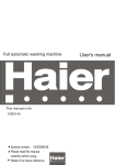
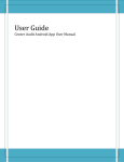
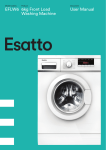
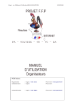
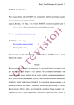
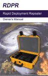
Pipe Line:
Connecting By Hose:
Install a Drop Leg for
draining the water in
the Pipeline
Continuous Downward
Slope - No U bend is
allowed
Receivers at the Top
Continuous Downward
Slope - No U bend is
allowed
Filters:
z
Only Ball Valves
should be used,
No needle valve
used
z
No Strainers in
front of the valves
STANDARD LIMITED WARRANTY
1. Never Combine
Two Filters for
draining
2. Install Separate
Drain Valves
Products of Trident Pneumatics Pvt Ltd are warranted for a period
of 1 year from the date of supply to be free from defects in
material and workmanship and operated in accordance to the
instructions outlined in the installation manual.
Trident Pneumatics Obligation under the warranty shall be limited
to repair or replace (at the discretion of Trident). Please send
material freight paid to the dealer from whom purchased, with a
copy of Purchase Invoice.
LDV 1000
LDV 2000
Level Sensing
Drain Valves
Installation &
Service Instructions
WARNING
Trident Pneumatics Pvt. Ltd.,
5/232 KNG Pudur Road, Coimbatore 641 108, India.
Ph : +91 422 2400492, Fax: +91 422 2401376,
Email : [email protected]
Website : www.tridentpneumatics.com
1. Valve discharges under pressure, stay away from
flow path.
2. Install and Remove only when depressurized and
electrically disconnected.
MODEL : LDV 1000 & 2000
SPECIFICATION LDV 1000:
Recommended Installation LDV1000 & 2000:
To ensure proper performance of your Trident Level Sensing
Drain Valve, proper selection is needed. Please verify your model
before reading this manual.
Inlet
Outlet
Pressure
Capacity
Operating Ambient
Electrical Connection
Overall Dimension
Receiver Installation LDV 1000:
PRINCIPLE OF OPERATION:
Level Sensing Drain Valves are designed for installation on
equipment requiring draining of accumulated fluids of compressed
air. The valves are opened based on condensate level in the
valve, once the water level reaches upper level, the sensor
senses the condensate and energizes the outlet solenoid valve,
the moment the condensate reaches lower level it de-energize
the outlet solenoid valve ensuring no loss of compressed air. A
Bi-color LED Indicator glows RED when energized and GREEN
when draining.
INSTALLATION PROCEDURE:
Inlet
Outlet
Pressure
Capacity
Operating Ambient
Electrical Connection
Overall Dimension
z
:
:
:
:
:
:
:
½" BSP (F)
½" BSP (F)
2 to 16 bar g
1000 scfm (Max.)
3 - 70oC, 0 - 100% RH
DIN 43650 Micro
237 x 118 x 165
G 3/ 4"
1. Continuous Downward
Slope for Inlet
2. Pressure Balance for
Bottom Inlet
Receiver Installation LDV 2000:
97.0
137.0
G 3/4"
118.0
115.0
237.5
165.0
z
The Drain Valve should
be well below the
Receiver Dish End
G 1/2"
MAINTENANCE:
Check the Drain function Daily.
Check the Valve function by pressing Test Button at
least weekly once.
Replace O-rings and seals every 3 Years
½" BSP (F)
¼" Hose Barb
2 to 10 bar g
250 scfm (Max.)
3 - 70oC, 0 - 100% RH
DIN 43650 Micro
115 x 97 x 137
SPECIFICATION LDV 2000:
1. Ensure pressure & voltage are as specified in the valve.
2. Prior to installing, close all pressure lines to vessel and blow
down the solid particles inside.
3. Install a manual shut off valve on drain line before the LDV.
This will enable to remove drain valve without interrupting
compressed air system.
4. Install valve as per the installation drawing shown below.
Before installing apply proper thread sealant.
5. Connect to the electrical source as per the specification
through a fused outlet.
6. Open shut off valve and switch ON power supply to operate
the Drain valve.
z
:
:
:
:
:
:
:
Top I nlet
1/2" B SP
Bottom Inl et
1/2" BSP
Outlet
1/2" BSP
The Pressure Balance
Line should be
minimum ¼",
Max. ½" Pipe sizes