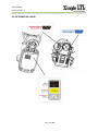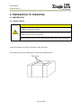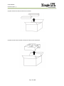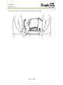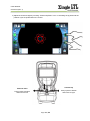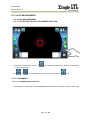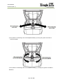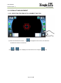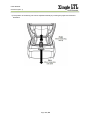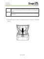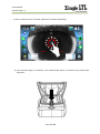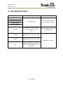
1
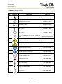
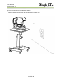
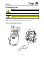
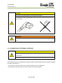
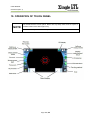
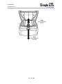
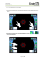
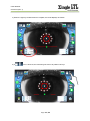
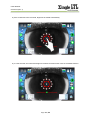
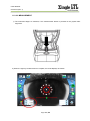
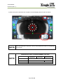
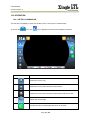
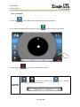
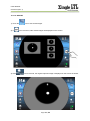
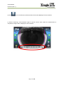
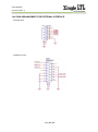
2014-06
GTUM-001 (Rev. 1)
User’s Manual
For Auto Ref-keratometer SINGLE LTL
This document is described by G2 Optic Co., Ltd.
Please read this manual carefully before using the device.
G2 Optic Co., Ltd.
B-1512 Woorimlions valley-Ⅱ 14, Sagimakgol-ro 45 beon-gil,
Jungwon-gu, Seongnam-si, Gyeonggi-do, Korea
Tel. +82-31-698-2332
Fax. +82-70-4369-4878
USER’S MANUAL
GTUM-001 (REV. 1)
CONTENTS
1. IMPORTANT NOTICE .......................................................................................................................................................... 1
2. SAFETY INFORMATION .................................................................................................................................................... 2
3. MAINTENANCE INFORMATION .................................................................................................................................... 5
3.1 USER MAINTENANCE ............................................................................................................................................ 5
3.2 WARRANTY REGULATION .................................................................................................................................. 5
4. SAFETY ...................................................................................................................................................................................... 6
4.1 SAFETY REGULATION .......................................................................................................................................... 6
4.2 PROPER USE .............................................................................................................................................................. 7
4.3 PRODUCT CHARACTERISTICS ........................................................................................................................ 8
5. DESCRIPTION OF COMPONENT ................................................................................................................................. 9
6. COMPOSITION OF PARTS WHICH CONTCT THE PATIENT ....................................................................... 11
7. STANDARD ACCESSORIES......................................................................................................................................... 12
8. LABELING REQUIREMENT .......................................................................................................................................... 13
8.1 MARKING PLATE ................................................................................................................................................... 13
8.2 INFORMATION LABEL ........................................................................................................................................ 14
9. PREPERATION TO OPERATING ................................................................................................................................ 15
9.1 PREPERATION ........................................................................................................................................................ 15
9.2 RECOVERY FROM POWER SAVE STATUS ............................................................................................. 22
10. OPERATION OF TOUCH PANEL ............................................................................................................................. 23
11. GENERAL OPERATION ................................................................................................................................................ 26
11.1 PREPARATION BEFORE MEASUREMENT ............................................................................................ 26
USER’S MANUAL
GTUM-001 (REV. 1)
11.2 REF MEASUREMENT ........................................................................................................................................ 30
11.2.1 AUTO MEASUREMENT ................................................................................................................................. 31
11.2.2 SEMI-AUTO MEASUREMENT.................................................................................................................... 41
11.2.3 MANUAL MEASUREMENT ......................................................................................................................... 51
11.3 KER MEASUREMENT........................................................................................................................................ 59
11.3.1 AUTO MEASUREMENT ................................................................................................................................. 59
11.3.2 SEMI-AUTO MEASUREMENT.................................................................................................................... 59
11.3.3 MANUAL MEASUREMENT ......................................................................................................................... 59
11.4 R/K MEASUREMENT ......................................................................................................................................... 60
11.4.1 AUTO MEASUREMENT ................................................................................................................................. 60
11.4.2 SEMI-AUTO MEASUREMENT.................................................................................................................... 60
11.4.3 MANUAL MEASUREMENT ......................................................................................................................... 60
11.5 DISPLAYING MEASUREMENT DATA ........................................................................................................ 61
12. ADDITIONAL OPERATION .......................................................................................................................................... 64
12.1 SELECTING THE ADDITIONAL MEASUREMENT .............................................................................. 64
12.2 OPERATION ........................................................................................................................................................... 66
12.2.1 RETRO-ILLUMINATION ....................................................................................................................... 66
12.2.2 CORNEA DIAMETER MEASUREMENT ....................................................................................... 70
12.2.3 CONTACT LENS BASE CURVE MEASUREMENT ................................................................ 72
12.2.4 PERIPHRAL KERATOMETRY MEASUREMENT ..................................................................... 74
13. AFTER USE ........................................................................................................................................................................ 75
14. SETTING ON THE MANU SCREEN ........................................................................................................................ 76
USER’S MANUAL
GTUM-001 (REV. 1)
15. MAINTENANCE ................................................................................................................................................................ 81
15.1 DAILY CHECKUP ................................................................................................................................................. 81
16. TROUBLESHOOTING ................................................................................................................................................... 83
17. SPECIFICATIONS AND PERFORMANCE ........................................................................................................... 84
18. GENERAL INFORMATION ON USAGE ................................................................................................................ 85
18.1 INTENDED USER PROFILE ........................................................................................................................... 85
18.2 ENVIRONMENTAL CONDITION OF USE ................................................................................................. 85
18.3 STORAGE, USAGE PERIOD .......................................................................................................................... 85
18.4 ENVIRONMENTAL CONDITIONS FOR PACKAGING IN STORAGE .......................................... 87
18.5 ELECTRIC RATING ............................................................................................................................................. 87
18.6 PINS ARRANGEMENT FOR EXTERNAL INTERFACE ..................................................................... 88
USER MANUAL
GTUM-001 (REV. 1)
1. IMPORTANT NOTICE
[Classification under the provision of 93/42/EEC(MDD)]
The SINGLE LTL is classified as Class Im device.
[Form of protection against electric shock]
The SINGLE LTL is classified as Class Im.
This product is always protected from electric shock when the power cord is connected between the
product and wall outlet.
Class Im is a product in which the protection against electric shock does not rely on basic insulation only,
but which includes an additional safety precaution in such a way that means are provided for the
connection of the product to the protective (ground) conductor in the fixed wiring of the installation in such
a way that accessible metal parts cannot become live in the event of a failure in the basic insulation. Use
a power outlet which is equipped with a grounding terminal.
[Degree of protection against electric shock]
The SINGLE LTL is classified as a device with a TYPE B APPLIED PART.
[Degree of protection against ingress of liquids]
The SINGLE LTL is classified as IPX0.
[Degree of protection against flammability]
The SINGLE LTL is classified as a device not suitable to be used in a potentially flammable environment.
Never use near flammable materials.
[Method(s) of sterilization or disinfection recommended by the manufacturer]
The forehead rest and chinrest should be wiped using a cloth dampened with soapy water as necessary.
[Mode of operation]
Classification of SINGLE LTL is continuous operation.
Electromagnetic waves discharged from mobile phones, radiotelegraphs, wireless toys can cause
malfunction of this product. Please keep away any device that can influence this product.
It is a compulsory obligation to learn the operating manual thoroughly, before installation, use, repair,
wash or adjustment of the auxiliary parts of this equipment. For user’s safety, please use this equipment
only after reading all the instructions included in this manual.
All the information in this manual has been checked out carefully and discerned as accurate one at the
time of publication. However, G2 Optic Co., Ltd. takes no responsibilities of the results caused by default,
omission, or misuse of it.
G2 Optic Co., Ltd. has rights to modify the product itself or specifications of the product without any prior
notice, as well as rights not to renew that modification on this manual.
G2 Optic Co., Ltd.
B-1512 Woorimlions valley-Ⅱ 14, Sagimakgol-ro 45 beon-gil,
Jungwon-gu, Seongnam-si, Gyeonggi-do, Korea
Tel. +82-31-698-2332
Fax. +82-70-4369-4878
All rights are reserved to G2 Optic Co., Ltd.
Page 1 / 89
USER MANUAL
GTUM-001 (REV. 1)
2. SAFETY INFORMATION
Accessory equipment connected to the analog and digital interfaces must be certified according to the
respective IEC/EN standards (e.g. IEC/EN 60950 for data processing equipment and IEC/EN 60601-1
for medical equipment).
Furthermore all configurations shall comply with the system standard EN 60601-1-2:2007. Everybody
who connects additional equipment to the signal input part or signal output part configures a medical
system, and is therefore responsible that the system complies with the requirements of the system
standard IEC 60601-1:2005+A1:2012.
If in doubt, consult the technical service department or your local representative.
For EU Countries
The following mark, the name and address of the EU representative shows compliance of the instrument
with Council Directive 93/42/EEC of 14 June 1993 as amended by Directive 2007/47/EC concerning
medical instruments.
Page 2 / 89
USER MANUAL
GTUM-001 (REV. 1)
SYMBOLS FOR SAFETY
No.
Symbol
Description
Reference
1
TYPE B APPLIED PART
IEC 60878-02-02
2
Protective earth (ground)
IEC 60417-5019
3
Alternating current
IEC 60417-5032
4
“On” (power)
IEC 60417-5007
5
“Off” (power)
IEC 60417-5008
6
Do not throw away with general household
waste
7
General warning sign
8
Warning: dangerous voltage
IEC 60878
9
Refer to instruction manual
ISO 7010-M002
10
General mandatory action sign
ISO 7010-M001
11
General prohibition sign
ISO 7010-P001
12
Keep away from rain
ISO 7000-0626
13
Use no hand hook
ISO 7000-0622
14
Fragile; handle with care
ISO 7000-0621
15
This way up
ISO 7000-0623
WEEE
Wastes of electrical and
electronic equipment
ISO 7010-W001
Page 3 / 89
USER MANUAL
GTUM-001 (REV. 1)
16
Handle with care
IATA regulations
17
Stacking limit by number
ISO 7000-2403
18
Authorized representative in the EC
EN 980-5.13
19
Manufacturer
EN 980-5.12
20
Serial number
ISO 7000-2498
21
Operating instruction
ISO 7000-1641
22
Do not reuse
ISO 7000-1051
23
Sufficient for 1
ISO 7000-0518
24
Temperature limit 10°C min. to 40°C max
ISO 7000-0632
25
Humidity limit 10% to 90% R.H.
ISO 7000-2620
26
Air pressure limit 800hPa to 1060hPa
ISO 7000-2621
Page 4 / 89
USER MANUAL
GTUM-001 (REV. 1)
3. MAINTENANCE INFORMATION
3.1 USER MAINTENANCE
To maintain the safety and performance of the equipment, never attempt to repair it yourself.
These tasks should be performed by an authorized service representative.
Maintenance tasks that can be performed by the user are as follow;
For details; follow instructions of user’s manual
3.2 WARRANTY REGULATION
The manufacturer, G2 Optic Co., Ltd. warrantees the end customer that the product will function properly,
have no material or manufacturing flaws for 24 months from the date of purchase under the flowing
conditions.
- In the case of valid complaints due to defects or a short delivery, manufacturer will make good its
warranty by replacing the product free of charge or repairing it as necessary.
- All other claims of any kind are excluded, especially claims for damages. In case of delayed performance,
gross negligence or criminal intent, this shall apply only if there are no compelling legal regulations to
the contrary.
- The manufacturer is not liable for defects and their consequences that arise from natural wear, improper
cleaning or servicing, the non-observance of instructions for use, servicing or connection, scale
formation or corrosion, impurities in the air and water supply, or chemical or electrical influences that
are unusual or impermissible according to the manufacturer’s specifications.
- The warranty does not generally extend to lamps, glassware, rubber parts and the color fastness of
plastic parts.
- No liability is assumed when defects or their consequences can arise from manipulations or changes to
the product by the customer or a third party.
- Claims from this warranty can only be asserted when the “Statement of Delivery” has been sent to the
manufacturer, and the original can be presented by the operator or user.
Page 5 / 89
USER MANUAL
GTUM-001 (REV. 1)
4. SAFETY
4.1 SAFETY REGULATION
The instrument SINGLE LTL as a medical instrument complies with the safety regulation EN 60601-1.
Safety is everyone’s obligation and responsibility. The safe use of this product is related to everyone such
as installer, user, operator and equipment’s manager. It must read and learn this user manual is
compulsory before installation, using, cleaning, fixing or operation of this product or its accessories. Pay
particular attention and be familiar with warning symbols about safety. If do not follow safety direction of
this manual, you can get injured or accident when you operate this product. After read carefully and
understand this manual, use this product.
This manual is in keep a place where you can find easily.
4.1.1 MEANING OF SYMBOLS
WARNINGS
This is provided to alert the user to potential serious consequence (death, injury, or
side effect) to the patient or the user.
CAUTION
Also it is provided to alert the user to use special care necessary for the safe and
effective use of the instrument. They may include actions to be taken to avoid effects
on patients or users that may not be potentially life threatening or result in serious
injury, but about which the user should be aware. Cautions are also provided to alert
the user to adverse effects on this instrument of use or misuse and the care
necessary to avoid such effects.
This explains compulsory obligation before use or operation.
This explains overall prohibition about installation, operation and maintenance.
Carelessness can cause considerable personnel and material loss.
NOTE
This is provided additional information.
Page 6 / 89
USER MANUAL
GTUM-001 (REV. 1)
4.2 PROPER USE
The user must ensure that that the instrument works properly and is in a satisfactory condition before
each use.
The instrument SINGLE LTL is intended only for use in the field of ophthalmology. It is impermissible to
use the product for a purpose for which it was not intended.
“PROPER USE” includes following all the instructions for use and ensuring that all inspections and service
tasks are performed.
Apply and meet the overarching guidelines and/or national laws, national regulations and the rules of
technology for medical instruments applicable for startup and use of the product for the intended purpose.
The user must observe the following:
- Only use properly operating equipment.
- Protect himself/herself and third parties from danger.
- Avoid contamination from the product.
During use, the following national regulations must be observed:
- The applicable health and safety regulations.
- The applicable accident prevention regulations.
To ensure that product maintains their value and are always ready for use, they must be serviced once a
year as recommended:
- The safety checks must be performed every year.
Repair and service of the product is authorized only to those who meet the requirements below:
- Technicians of authorized dealers specially trained by the manufacturer, G2 Optic Co., Ltd.
- The trained technicians of manufacturer’s branches.
INFORMATION ON ELECTROMAGNETIC COMPATIBILITY
Based on EN 60601-1-2 concerning the electromagnetic compatibility of electromedical instruments, we need to point out that:
NOTE
- medical electrical instruments are subject to special measures regarding
electromagnetic compatibility and must be operated in accordance with G2 Optic
Co., Ltd. Assembly instructions;
- portable and mobile high-frequency communications instruments can influence
medical electronics.
Page 7 / 89
USER MANUAL
GTUM-001 (REV. 1)
CAUTION
DAMAGE BY USING IMPROPER PARTS
If parts from other suppliers, not manufacturer are used, it can influence quality of
the product.
Use only the parts authorized by manufacturer, G2 Optic Co., Ltd.
The manufacturer, G2 Optic Co., Ltd. cannot guarantees that parts not delivered by
manufacturer will correspond with EMC requirements of EN 60601-1-2.
DISPOSAL
For environment and safety of human, wastes must be recycled or separated.
Please contact your local authorized dealer if you have any questions about
recycling of the product.
4.3 PRODUCT CHARACTERISTICS
The instrument projects the infrared dots of light onto the retina and the reflection of the dots are captured
by a CCD camera.
4.3.1 REFRACTIVE MEASUREMENT (REF)
Internal computer analyzes the image and calculates the spherical, cylindrical and axial values.
4.3.2 KERATOMETRY MEASUREMENT (KER)
Internal computer analyzes the image and calculates the curvature radius, corneal astigmatic axis and
the corneal refractive value.
INTENDED USE
NOTE
- The instrument SINGLE LTL is designed to measure the refraction, keratometry
and peripheral keratometry of children and adults in the field of ophthalmology.
- The instrument may only be used by medical professionals.
Page 8 / 89
USER MANUAL
GTUM-001 (REV. 1)
5. DESCRIPTION OF COMPONENT
Page 9 / 89
USER MANUAL
GTUM-001 (REV. 1)
Description
Function
LCD Screen
shows all the information as well as measurement results.
Measurement Button
allows to measure the patient’s eye.
Status LED
shows status of instrument.
Joystick
allows to move measuring unit.
Chinrest Unit
supports the patient’s chin & forehead during measurement.
Chinrest
supports the patient’s chin during measurement.
Chinrest paper pin
fixes chinrest papers.
Power switch
allows to turn on the instrument.
Page 10 / 89
USER MANUAL
GTUM-001 (REV. 1)
Auxiliary lights
helps to show the patient’s eye clearly on the screen.
Forehead rest
supports the patient’s head during measurement.
Measuring unit
carries out to measure the patient’s eye.
Base unit
helps measuring unit to measure and supplies power to
measuring unit.
Measuring window
shows accommodation target to the patient.
Rubber foot
fixes body of instrument on the table.
Fuse Holder
keeps safe condition in case of over-current.
Power Inlet
supplies electric-power to body of instrument.
Video out
allows to display on external monitor.
RSC-232Port
allows to communicate with other electric devices.
WARNINGS
Insert a plastic cover on the unused interface ports such as RSC-232C & Video port
external connectors to avoid damage due to water spills or humidity.
6. COMPOSITION OF PARTS WHICH CONTCT THE PATIENT
Forehead rest
Silicon rubber
Chinrest
Silicon rubber
Chinrest unit
Non-flammable grade FV-0
Acrylonitrile Butadiene and Styrene
Page 11 / 89
USER MANUAL
GTUM-001 (REV. 1)
7. STANDARD ACCESSORIES
The following accessories are standard. Make sure that all these items are included (quantity).
Power code (1)
Chinrest paper pin (2)
Model eye (1)
KKP-4891R
GT-SLMP-0378
GT-SLAC-0103
Chinrest paper (1)
Dust cover (1)
User’s Manual (1)
GT-SLAC-0101
GT-SLAC-0102
GTUM-001
Fuse (2)
T2AL250V, 5x20mm
Using non-genuine parts can cause equipment failure. The manufacturer, G2 Optic
Co., Ltd. strongly recommends use of guaranteed parts from the manufacturer.
The model eye (GT-SLAC-0103) needs to be handled carefully due to potential
scratching by tiny particles of dust and alteration from environmental factors.
Page 12 / 89
USER MANUAL
GTUM-001 (REV. 1)
8. LABELING REQUIREMENT
8.1 MARKING PLATE
CE Mark by EC directive 93/42
Notice about waste disposal after use
TYPE B APPLIED PART
Refer to instruction manual
Product name
Functional name
Manufacturer’s serial number
Power supply
Power consumption
Weight
Country of origin
Manufacturer’s company name, address
Specified Authorized EC representative by
manufacturer
Page 13 / 89
USER MANUAL
GTUM-001 (REV. 1)
8.2 INFORMATION LABEL
Page 14 / 89
USER MANUAL
GTUM-001 (REV. 1)
9. PREPERATION TO OPERATING
9.1 PREPERATION
9.1.1 INSTALLATION
CAUTION
To prevent damage and injuries, do not install the instrument on an uneven,
unsteady or sloped floor surface.
When setting the instrument on the table, be careful not to injury the patient’s fingers
between the instrument and the table.
When moving the instrument, two people should lift the bottom side of the product.
1) Place the packing box with the instrument on the stable floor.
2) Cut plastic strings using safe scissors and remove the adhesive tape.
Page 15 / 89
USER MANUAL
GTUM-001 (REV. 1)
3) Open the box and remove PE forms in the box.
4) Open the inner box and then remove PE forms on the instrument.
Page 16 / 89
USER MANUAL
GTUM-001 (REV. 1)
5) Take out the instrument of the box and hold the instrument as follows.
Page 17 / 89
USER MANUAL
GTUM-001 (REV. 1)
6) Place the instrument on the stable table as follow.
Distance between the instrument and wall outlet should be within 2 m.
Page 18 / 89
USER MANUAL
GTUM-001 (REV. 1)
9.1.2 CONNECTING THE POWER
WARNING
Make sure that the power cord is connected to AC 3-pins socket equipped with
grounding.
CAUTION
To avoid electric shocks, do not touch the power cord with wet hands.
1) Make sure that the power switch at the bottom of the instrument is ‘OFF’ (O).
2) Connect the power cord to the power inlet.
3) Insert the power cord into the AC 3-pins socket.
Page 19 / 89
USER MANUAL
GTUM-001 (REV. 1)
CAUTION
Never touch any parts related to electricity with wet hands.
To avoid electric shock caused by the power cord, please using the bent power cord
only as follows.
WARNING
The power cord which is suitable for the policy and law of local country should be
used.
9.1.3 CONNECTION OF EXTERNAL INTERFACE
CAUTION
To avoid electric shock, do not touch the external connection terminal and patient at
the same time.
Never touch any parts related to electricity with wet hands.
This instrument can be connected to the external monitor, external thermal printer, personal computer
and other external device.
1) Connect the connection cable to the external interface port of the instrument.
2) Connect the other side of the connection cable to the external interface.
Page 20 / 89
USER MANUAL
GTUM-001 (REV. 1)
9.1.4 SETTING CHINREST PAPER
Never reuse the chinrest paper to prevent cross-contaminants that can cause skin
disease.
Page 21 / 89
USER MANUAL
GTUM-001 (REV. 1)
9.2 RECOVERY FROM POWER SAVE STATUS
The instrument has power saving function for protecting electrical circuit and saving electricity. When the
instrument is not operated during the setting time in MENU, the screen saver will be activated.
1) Touch the touch panel or operate the joystick.
2) After few seconds, the measurement screen is displayed and measurement can start.
Page 22 / 89
USER MANUAL
GTUM-001 (REV. 1)
10. OPERATION OF TOUCH PANEL
The instrument has a touch panel. Never use any sharp tools such as a pen or
NOTE
needle. Please touch with fingers only.
Do not touch two points on the touch panel at the same time.
Page 23 / 89
USER MANUAL
GTUM-001 (REV. 1)
Icon
Function
Measuring unit is moved horizontal position to right eye.
Measuring unit is moved horizontal position to left eye.
Reserve the screen
-Show general information of the instrument such as VD, STEP and CYL sign.
- In case of KER mode, INDEX, STEP and CYL sign are displayed.
- When the measurement is completed both eyes, this icon is changed to
icon with PD value.
Display the measurement result.
If the external printer is connected, the measurement result can be printed.
Change the measurement mode.
: Refractive measurement only
: Kertometry measurement only
: Simultaneous refractive measurement and Keratometry measurement
Move the measuring unit in the patient’ direction.
Move the measuring unit in the operator’s direction.
Measurement is started manually.
If focusing and alignment is completed, this icon is changed to
icon.
To measure the patient who has implanted IOL due to cataract and presbyopia, touch
this icon. When this function is executed, this icon is changed to
Page 24 / 89
icon.
USER MANUAL
GTUM-001 (REV. 1)
Clear all measurement result data and return to the measurement screen.
Show the measurement result data
The chinrest goes up vertically.
The chinrest goes down vertically.
Change the tracking method
: Auto measuring function after auto tracking & focusing
: Auto tracking & focusing without measurement
: Manual measuring without auto function
Page 25 / 89
USER MANUAL
GTUM-001 (REV. 1)
11. GENERAL OPERATION
11.1 PREPARATION BEFORE MEASUREMENT
11.1.1 TURNING ON THE INSTRUMENT
1) Make sure the power cord is connected between the product and the wall outlet.
2) Turn on the power switch.
If touching the cord or switch with wet hands, it can cause electric shock.
This instrument requires periodic checking for any damage of the power cord
because it can cause fire or electric shock.
3) After startup screen is displayed, the measurement screen is displayed in a few seconds.
Page 26 / 89
USER MANUAL
GTUM-001 (REV. 1)
11.1.2 SELECTING THE MEASUREMENT MODE
This instrument has three measurement modes as follows:
: Refractive measurement only
: Kertometry measurement only
: Simultaneous refractive measurement and Keratometry measurement
1) Check that the measurement screen is on.
2) Touch the “Measurement mode” icon on the touch panel and select the one of them and indicate the
icon is changed.
Never touch the touch panel with wet hands to prevent electric shock and
malfunction.
Do not touch two points on the touch panel at the same time.
NOTE
If the patient who has implanted IOL is measured REF or R/K, IOL function should
be activated by touching IOL icon before measurement.
Page 27 / 89
USER MANUAL
GTUM-001 (REV. 1)
11.1.3 POSITIONING THE PATIENT
CAUTION
Do not insert fingers under the chinrest, it can cause injury.
When operating “Chinrest Up/Down”, be careful not to catch the patient’ fingers
under the chinrest. Give the patient a warning.
When operating the instrument, be careful that it does not touch the patient’s face.
If it touches, wipe the instrument.
Before the patient’s forehead touches the forehead rest, there are no contaminants
on the forehead rest. It can cause skin disease.
The chinrest paper should be replaced every measurement.
NOTE
Adjust properly the height of the chair and the table that the product is placed on.
An uncomfortable position can affect the accuracy of measurement result.
1) Make sure that the patient seat comfortably in a safe chair so that the patient’s chin is positioned on
the chinrest safely.
2) Adjust the height of the instrument table for patient to lean his/her chin on the chinrest comfortably.
3) Place the patient’s chin on the chinrest and check that his/her forehead is touching to the forehead
rest.
Page 28 / 89
USER MANUAL
GTUM-001 (REV. 1)
4) Adjust the chinrest height by touching “Chinrest Up/Down” icon or controlling the joystick until the
patient’s eyes are positioned on the screen.
Chinrest down
Chinrest up
Push joystick to bottom
and incline to left
Push joystick to bottom
and incline to right.
Page 29 / 89
USER MANUAL
GTUM-001 (REV. 1)
11.2 REF MEASUREMENT
CAUTION
When operating the instrument, be careful that it does not touch the patient’s face.
If it touches, wipe the instrument.
If the eyelid and eyelashes cover the pupil, AUTO MEASUREMENT mode may not
be possible. In this case, tell the patient to open their eyes as wide as possible or
lift the eyelid to allow for measurement.
Auto measurement mode may not be possible due to frequent blinks or existing
abnormalities in the corneal surface caused corneal disease etc.
NOTE
If the patient blinks or measurement is taken without proper alignment, the error
message will be displayed on the screen.
If the pupil diameter of patient’s eye is less than 2.0mm, this instrument could not
measure the refractive power.
When measuring a patient who has IOL implant, IOL function should be activated
by pressing the IOL button before measurement.
Page 30 / 89
USER MANUAL
GTUM-001 (REV. 1)
11.2.1 AUTO MEASUREMENT
11.2.1 AUTO MEASUREMENT
11.2.1.1 SELECTING THE AUTO ALGINMENT FUNCTION
1) Check the measurement screen.
If
icon appears on the screen, the auto measurement
function is executed.
2) If
or
icon is displayed, touches that icon to change to
icon.
11.2.1.2 ALIGNMENT
11.2.1.2.1 ALIGNING WITH JOYSTICK
1) The position of measuring unit can be adjusted horizontally by inclining the joystick to left or right.
Page 31 / 89
USER MANUAL
GTUM-001 (REV. 1)
2) The position of measuring unit can be adjusted laterally by turning the joystick clockwise or
counterclockwise.
3) The position of measuring unit can be adjusted vertically by inclining the joystick to forward or
backward.
Page 32 / 89
USER MANUAL
GTUM-001 (REV. 1)
Page 33 / 89
USER MANUAL
GTUM-001 (REV. 1)
11.2.1.2.2 ALIGNING WITH TOUCH PANEL
1) The position of measuring unit can be adjusted horizontally by touching left/right side of touch
panel.
2) The position of measuring unit can be adjusted laterally by touching
icon of the touching panel.
Page 34 / 89
and
USER MANUAL
GTUM-001 (REV. 1)
3) The position of measuring unit can be adjusted vertically by touching upper/bottom of touch panel.
Page 35 / 89
USER MANUAL
GTUM-001 (REV. 1)
11.2.1.3 MEASUREMENT
1) If
icon is touched, measuring unit is moved to patient’s right eye.
2) If the central red circle is touched, alignment is started automatically.
Page 36 / 89
USER MANUAL
GTUM-001 (REV. 1)
If the focus is out of focus or measurement is not carried out even though central
red circle is touched, please touch the central red circle again until the measurement
NOTE
is started.
If the pupil diameter is less than 2.0 mm, the measurement value is not appeared
on the screen.
3) In a few seconds, the instrument begins to measure for times which is set on the MANU function.
Page 37 / 89
USER MANUAL
GTUM-001 (REV. 1)
4) When the right eye measurement is complete, the result displays as follows:
5) If
icon is touched, the measuring unit moves to patient’s left eye.
Page 38 / 89
USER MANUAL
GTUM-001 (REV. 1)
6) If the central red circle is touched, alignment is started automatically.
8) In a few seconds, the instrument begins to measure for times which is set on the MANU function.
Page 39 / 89
USER MANUAL
GTUM-001 (REV. 1)
9) When both eyes measurement is complete, the result displays with PD value as follows:
NOTE
If Auto measurement mode does not work, select Manual measurement mode.
Auto measurement mode may not work depending on the corneal conditions.
Page 40 / 89
USER MANUAL
GTUM-001 (REV. 1)
11.2.2 SEMI-AUTO MEASUREMENT
11.2.2.1 SELECTING THE SEMI-AUTO ALGINMENT FUNCTION
1) Check the measurement screen.
If
icon appears on the screen, the semi-auto
measurement function is executed.
2) If
or
icon is displayed, touches that icon to change to
Page 41 / 89
icon.
USER MANUAL
GTUM-001 (REV. 1)
11.2.2.2 ALIGNMENT
11.2.2.2.1 ALIGNING WITH JOYSTICK
1) The position of measuring unit can be adjusted horizontally by inclining the joystick to left or right.
2) The position of measuring unit can be adjusted laterally by turning the joystick clockwise or
counterclockwise.
Page 42 / 89
USER MANUAL
GTUM-001 (REV. 1)
3) The position of measuring unit can be adjusted vertically by inclining the joystick to forward or
backward.
Page 43 / 89
USER MANUAL
GTUM-001 (REV. 1)
11.2.2.2.2 ALIGNING WITH TOUCH PANEL
1) The position of measuring unit can be adjusted horizontally by touching left/right side of touch
panel.
2) The position of measuring unit can be adjusted laterally by touching
icon of the touching panel.
Page 44 / 89
and
USER MANUAL
GTUM-001 (REV. 1)
3) The position of measuring unit can be adjusted vertically by touching upper/bottom of touch panel.
Page 45 / 89
USER MANUAL
GTUM-001 (REV. 1)
11.2.2.3 MEASUREMENT
1) If
icon is touched, measuring unit is moved to patient’s right eye.
2) If the central red circle is touched, alignment is started automatically.
Page 46 / 89
USER MANUAL
GTUM-001 (REV. 1)
If the focus is out of focus or measurement is not carried out even though central
red circle is touched, please touch the central red circle again until the measurement
NOTE
is started.
If the pupil diameter is less than 2.0 mm, the measurement value is not appeared
on the screen.
3) The instrument begins to measure, if the measurement button is pressed on the joystick after
alignment.
Page 47 / 89
USER MANUAL
GTUM-001 (REV. 1)
4) When the right eye measurement is complete, the result displays as follows:
5) If
icon is touched, the measuring unit moves to patient’s left eye.
Page 48 / 89
USER MANUAL
GTUM-001 (REV. 1)
6) If the central red circle is touched, alignment is started automatically.
8) The instrument begins to measure, if the measurement button is pressed on the joystick after
alignment.
Page 49 / 89
USER MANUAL
GTUM-001 (REV. 1)
9) When both eyes measurement is complete, the result displays with PD value as follows:
Page 50 / 89
USER MANUAL
GTUM-001 (REV. 1)
11.2.3 MANUAL MEASUREMENT
11.2.3.1 SELECTING THE MANUAL ALIGNMENT FUNCTION
1) Check the measurement screen.
If
icon appears on the screen, the manual
measurement function is executed.
2) If
or
icon is displayed, touches that icon to change to
Page 51 / 89
icon.
USER MANUAL
GTUM-001 (REV. 1)
11.2.3.2 ALIGNMENT
11.2.3.2.1 ALIGNING WITH JOYSTICK
1) The position of measuring unit can be adjusted horizontally by inclining the joystick to left or right.
2) The position of measuring unit can be adjusted laterally by turning the joystick clockwise or
counterclockwise.
Page 52 / 89
USER MANUAL
GTUM-001 (REV. 1)
3) The position of measuring unit can be adjusted vertically by inclining the joystick to forward or
backward.
Page 53 / 89
USER MANUAL
GTUM-001 (REV. 1)
11.2.3.2.2 ALIGNING WITH TOUCH PANEL
1) The position of measuring unit can be adjusted horizontally by touching left/right side of touch
panel.
2) The position of measuring unit can be adjusted laterally by touching
icon of the touching panel.
Page 54 / 89
and
USER MANUAL
GTUM-001 (REV. 1)
3) The position of measuring unit can be adjusted vertically by touching upper/bottom of touch panel.
Page 55 / 89
USER MANUAL
GTUM-001 (REV. 1)
11.2.3.3 MEASUREMENT
1) The instrument begins to measure, if the measurement button is pressed on the joystick after
alignment.
2) When the right eye measurement is complete, the result displays as follows:
Page 56 / 89
USER MANUAL
GTUM-001 (REV. 1)
2) Move the measuring unit to patient’s left eye.
3) The instrument also begins to measure, if the measurement button is pressed on the joystick after
alignment.
Page 57 / 89
USER MANUAL
GTUM-001 (REV. 1)
4) When both eyes measurement is complete, the result displays with PD value as follows:
NOTE
If the pupil diameter is less than 2.0 mm, the measurement value is not appeared
on the screen.
COMPARATIVE TABLE FOR MEASUREMENT FUNCTION
Alignment
NOTE
AUTO
SEMI-AUTO
Focusing
Measurement
AUTO
AUTO
MANUAL
MANUAL
MANUAL
Page 58 / 89
USER MANUAL
GTUM-001 (REV. 1)
11.3 KER MEASUREMENT
CAUTION
When operating the instrument, be careful that it does not touch the patient’s face.
If it touches, wipe the instrument.
If the eyelid and eyelashes cover the pupil, AUTO MEASUREMENT mode may not
be possible. In this case, tell the patient to open their eyes as wide as possible or
lift the eyelid to allow for measurement.
Auto measurement mode may not be possible due to frequent blinks or existing
NOTE
abnormalities in the corneal surface caused corneal disease etc.
If the patient blinks or measurement is taken without proper alignment, the error
message will be displayed on the screen.
If “D” is selected in “m/D” option of the MENU, K1 & K2 would be displayed instead
of R1 & R2 to distinguish m & D mode.
11.3.1 AUTO MEASUREMENT
SEE “11.2.1 AUTO MEASUREMENT”
11.3.2 SEMI-AUTO MEASUREMENT
SEE “11.2.2 SEMI-AUTO MEASUREMENT”
11.3.3 MANUAL MEASUREMENT
SEE “11.2.3 MANUAL MEASUREMENT”
Page 59 / 89
USER MANUAL
GTUM-001 (REV. 1)
11.4 R/K MEASUREMENT
CAUTION
When operating the instrument, be careful that it does not touch the patient’s face.
If it touches, wipe the instrument.
If the eyelid and eyelashes cover the pupil, AUTO MEASUREMENT mode may not
be possible. In this case, tell the patient to open their eyes as wide as possible or
lift the eyelid to allow for measurement.
Auto measurement mode may not be possible due to frequent blinks or existing
abnormalities in the corneal surface caused corneal disease etc.
If the patient blinks or measurement is taken without proper alignment, the error
NOTE
message will be displayed on the screen.
If the pupil diameter of patient’s eye is less than 2.0mm, this instrument could not
measure the refractive power.
When measuring a patient who has IOL implant, IOL function should be activated
by pressing the IOL button before measurement.
If “D” is selected in “m/D” option of the MENU, K1 & K2 would be displayed instead
of R1 & R2 to distinguish m & D mode.
11.4.1 AUTO MEASUREMENT
SEE “11.2.1 AUTO MEASUREMENT”
11.4.2 SEMI-AUTO MEASUREMENT
SEE “11.2.2 SEMI-AUTO MEASUREMENT”
11.4.3 MANUAL MEASUREMENT
SEE “11.2.3 MANUAL MEASUREMENT”
Page 60 / 89
USER MANUAL
GTUM-001 (REV. 1)
11.5 DISPLAYING MEASUREMENT DATA
1) Touch the
icon on the touch panel after measurement, measurement data will display as
follows:
Page 61 / 89
USER MANUAL
GTUM-001 (REV. 1)
2) If touch the
,
Icon
or
icon on the touch panel, the correspondent data will display.
Function
Display the refractive measurement data
Display the keratometry measurement data
Display the CLBC(contact lens base curve) measurement data
Page 62 / 89
USER MANUAL
GTUM-001 (REV. 1)
3) To print out or transmit to other device the measurement data, touch the
4)
If the
or
Icon
icon.
icon is touched, return to the measurement screen.
Function
Return to the measurement screen only.
Return to the measurement screen with clearance off all
measurement data
Page 63 / 89
USER MANUAL
GTUM-001 (REV. 1)
12. ADDITIONAL OPERATION
12.1 SELECTING THE ADDITIONAL MEASUREMENT
1) If the measurement mode icon is touched, additional measurement icons are displayed on the screen
as follows:
Page 64 / 89
USER MANUAL
GTUM-001 (REV. 1)
2) Touch the one of additional measurement icons on the screen that you want to measure.
Icon
Function
RETRO-ILLUMINATION:
It is available to check the condition of the cornea prior to measurement.
CORNEA DIAMETER MEASUREMENT:
Measure the diameter of cornea.
CONTACT LENS BASE CURVE MEASUREMENT:
Measure the contact lens base curve.
PERIPHERAL KERATOMETRY MEASUREMENT:
Measure the keratometry of peripheral cornea as well as central keratometry
measurement.
Page 65 / 89
USER MANUAL
GTUM-001 (REV. 1)
12.2 OPERATION
12.2.1 RETRO-ILLUMINATION
This function is available to check the condition of the cornea prior to measurement.
1) If touch the
icon, this
icon is appeared and the screen displays as follows:
Icon
Function
Capture the screen only.
Capture the screen after refractive measurement.
Capture the screen after refractive measurement with IOL function.
Display the saved image.
Increase the value of LED brightness which is selected.
Page 66 / 89
USER MANUAL
GTUM-001 (REV. 1)
Decrease the value of LED brightness which is selected.
Select the LED to be adjusted.
The index of captured image
The brightness of REF LED
This is the adjustable brightness for illumination which is reflected on the
patient’s cornea.
The brightness of AUXILIARY LIGHT
If this value is increased, the screen is bright.
The brightness of PATINT’S CHART
If this value is increased, the chart which can be seen by patient is
brighter.
This RETRO-ILLUMINGATION is used only for pre-checking in order to measure
accuracy result.
Never use for diagnosis of any diseases such as cataract, glaucoma and etc..
Page 67 / 89
USER MANUAL
GTUM-001 (REV. 1)
12.2.2.1 CAPTURE
1) Touch the
icon to capture the screen after alignment and focusing.
2) The captured image displays as follow. Touch the
3) Then, touch the
If
icon to save the current image.
icon to leave to measurement mode.
or
is touched instead of the
measurement result displays as follows:
NOTE
Page 68 / 89
icon, refractive
USER MANUAL
GTUM-001 (REV. 1)
12.2.1.2 DISPLAY
1) Touch the
2) If
3) If the
icon to see saved images.
icon is touched, other saved images are displayed on the screen.
icon is touched, the original captured image is displayed on the screen as follows.
Page 69 / 89
USER MANUAL
GTUM-001 (REV. 1)
12.2.2 CORNEA DIAMETER MEASUREMENT
1) Touch the
icon to get the still image on the screen.
2) If the captured image is displayed, move vertical positions of two violet bars using this
icon until violet bars meet both edges of cornea.
Page 70 / 89
or
USER MANUAL
GTUM-001 (REV. 1)
3) If the
icon is touched, the measured value is saved and displayed on the result box.
4) Perform measuring cornea diameter again to get the correct value. When the measurement is
completed, average value is displayed on the result box.
Page 71 / 89
USER MANUAL
GTUM-001 (REV. 1)
12.2.3 CONTACT LENS BASE CURVE MEASUREMENT
12.2.3.1 ATTACHING CONTACT LENS
1) Put a little water on the concave surface of the model eye as follows.
2) Attach the contact lens on the model eye cap.
Page 72 / 89
USER MANUAL
GTUM-001 (REV. 1)
12.2.3.2 MEASUREMENT
1) After alignment and focusing as “11.2.2 ALIGNMENT”, touch the
2) After measurement, its data is displayed on the result box as follows.
Page 73 / 89
icon on the screen.
USER MANUAL
GTUM-001 (REV. 1)
12.2.4 PERIPHRAL KERATOMETRY MEASUREMENT
1) The central keratometry measurement is performed in the same way as the refractive measurement.
2) Let the patient look at the green lights and perform peripheral keratometry measurement as following
procedure.
NOTE
Inferior
Superior
Nasal/Temporal
Nasal/Temporal
When the peripheral keratometry measurement, advice the patient to turn pupil only,
not forehead.
Page 74 / 89
USER MANUAL
GTUM-001 (REV. 1)
13. AFTER USE
1) Move measuring unit to place properly on the center of vase unit by touching the touch panel or
operating joy stick.
2) Turn off the power switch (O).
NOTE
When external devices are connected with the instrument, turn off the power of both
devices. (If power switch is provided.)
3) Unplug the power cord from a 3 pins AC inlet with grounding.
CAUTION
Never touch any parts related to electricity with wet hands.
NOTE
When the instrument is not used for a long period, unplug the power cord and detach
the cable connected to the external interface ports.
WARNING
When not using the instrument for extended periods of time, put the dust
cover (GT-SLAC-0102) on the instrument to prevent dirty.
Page 75 / 89
USER MANUAL
GTUM-001 (REV. 1)
14. SETTING ON THE MANU SCREEN
1) Touch the
icon on the screen of the measurement mode.
2) When displaying screen appears as below, touch the
Page 76 / 89
icon.
USER MANUAL
GTUM-001 (REV. 1)
3) Then, Touch the “MENU 01”, “MENU 02”, “OFFSET”, “LABEL”, or “SETUP” icon which desire to change.
4) Touch the article to be changed.
Page 77 / 89
USER MANUAL
GTUM-001 (REV. 1)
LIST OF MENU FUNCTION
Descriptions
Options
Details
Default
MENU 01
Related to the measurement conditions
0
VD value is set to 0 mm (for contact lens).
12
VD value is set to 12 mm.
VD
12
13.5
15
CYL
VD value is set to 15 mm.
-
The sign of astigmatic power is “-“.
+
The sign of astigmatic power is “+“.
-/+
0.01
STEP D
VD value is set to 13.5 mm.
0.12
0.25
0.01
STEP mm
0.05
The sign of astigmatic power is “-“ and “+”.
Refractive measurement result is displayed by 0.01 D
step.
Refractive measurement result is displayed by 0.12 D
step.
Refractive measurement result is displayed by 0.25 D
step.
Curvature measurement result is displayed by 0.01 mm
step.
Curvature measurement result is displayed by 0.05 mm
step.
mm
Curvature results are printed as R1 & R2 in KER mode.
D
Curvature results are printed as K1 & K2 in KER mode.
mm / D
INDEX
MODE
-
0.25
0.01
mm
1.3375
Corneal refractive index is set to 1.3375.
1.3320
Corneal refractive index is set to 1.3320.
1.3360
Corneal refractive index is set to 1.3360.
REF
Initial measurement mode is REF when power on.
KER
Initial measurement mode is KER when power on.
R/K
Initial measurement mode is R/K when power on.
ON
Beep sounds.
OFF
Beep does not sound.
BEEP
1.3375
REF
ON
Page 78 / 89
USER MANUAL
GTUM-001 (REV. 1)
MENU 02
Related to the measurement conditions
ON
Measurement / Print number is displayed.
OFF
Measurement / Print number is not displayed.
YMD
Date is displayed as year-month-day.
MDY
Date is displayed as month-day-year.
DMY
Date is displayed as day-month-year.
ALL
All the measurement results are printed out.
NUMBER
DATE TYPE
ON
PRINT
ALL
ECONO
REF/KER
PRINT SEQ
LEFT/RIGHT
AUTO
Average of measurement results are only printed out.
Measurement results are printed in terms of REF or KER.
Measurement results are printed in terms of LEFT or
RIGHT.
REF/KER
Auto cut is carried out.
PAPER CUT
AUTO
MANUAL
Auto cut is not carried out.
1
The number of continuous measurement is 1.
3
The number of continuous measurement is 3.
5
The number of continuous measurement is 5.
7
The number of continuous measurement is 7.
REPEAT
3
3 min
Power save status in 3 min after operation.
5 min
Power save status in 5 min after operation.
10 min
Power save status in 10 min after operation.
15 min
Power save status in 15 min after operation.
POWER SAVE
AUTO /
MANUAL
YMD
3 min
AUTO-1
Initial measurement mode is auto.
AUTO-2
Initial measurement mode is auto for binocular eyes.
AUTO-3
Initial measurement mode is auto for binocular eyes with
printing without any operation.
SEMI
MANUAL
Initial measurement mode is semi-auto.
Initial measurement mode is manual.
OFFSET
Related to adjusting of measurement results
Page 79 / 89
AUTO-3
USER MANUAL
GTUM-001 (REV. 1)
REF SPH
SPH value of REF measurement is adjusted.
0
REF CYL
CYL value of REF measurement is adjusted.
0
REF AXIS
AXIS value of REF measurement is adjusted.
0
KER R1
R1 value of KER measurement is adjusted.
0
KER R2
R2 value of KER measurement is adjusted.
0
KER AXIS
AXIS value of KER measurement is adjusted
0
CLBC R1
R1 value of CLBC measurement is adjusted.
0
CLBC R2
R2 value of CLBC measurement is adjusted.
0
AXIS value of CLBC measurement is adjusted.
0
PD value is adjusted.
0
CLBC AXIS
PD ADJ
LABEL
Related to message function
PRINT LABEL
Input the string of up to 48 characters.
G2 OPTIC
CO.,LTD.
OFFSET
Related to control of hardware & display
LCD LIGHT
Brightness of LCE panel is adjusted.
0
FOCUS ADJ
Sensitivity of auto focus is adjusted.
30
2400
Baud rate is set to 2400 bps.
4800
Baud rate is set to 4800 bps.
9600
Baud rate is set to 9600 bps.
19200
Baud rate is set to 19200 bps.
38400
Baud rate is set to 38400 bps.
57600
Baud rate is set to 57600 bps.
115200
Baud rate is set to 115200 bps.
460800
Baud rate is set to 460800 bps.
BAUD RATE
INTERFACE
LANGUAGE
38400
PRINT &
RSC 232C
RSC 232C
ONLY
ENGLISH
OTHER
Data are transferred to printer & RSC 232C port.
Data are transferred to RSC 232C port only.
Language of characters is set to ENGLISH.
Language of characters is set to other.
Page 80 / 89
PRINT &
RSC 232C
ENGLISH
USER MANUAL
GTUM-001 (REV. 1)
15. MAINTENANCE
15.1 DAILY CHECKUP
15.1.1 CHECKING THE MEASURING ACCURACY
1) The model eye (GT-SLAC-0103) accompanied with the instrument should be measured and the
accuracy is checked at regular intervals.
2) To set up the model eye, insert the guide groove of the model eye to the chinrest paper pin.
WARNING
If the measurement result differed materially, contact your local authorized dealer.
15.1.2 CLEANING THE INSTRUMET
- If dust on the measuring window, blow off dust by a blower.
- If fingerprints and oil spots on the measuring window, below off dust by a blower and wipe the surface
with isopropyl alcohol using the clean gauze.
- If the instrument cover is dirty, wipe the surface with a dry soft cloth. Never use solvents or a chemical
duster.
Page 81 / 89
USER MANUAL
GTUM-001 (REV. 1)
15.1.3 CLEANING THE FOREHEAD REST AND CHINREST
- Wipe the forehead rest and chinrest with a cloth moistened by a tepid solution of neutral detergent for
kitchenware.
15.1.4 DAILY MAINTENANCE
- For this instrument, dust may cause the failure. When not in use, place the dust cover on the
instrument.
- When not in use, turn off the power switch.
15.1.5 ORDERING CONSUMABLE ITEMS
- When ordering consumable items, tell the product name, control-code and quantity to your local
authorized dealer.
Product name
Control-code
Power code
KKP-4891R
Chinrest paper
GT-SLAC-0101
Dust cover
GT-SLAC-0102
Fuse
T2AL250V
The information of all the spare parts including above items is provided in the website:
www.g2optic.com.
Page 82 / 89
USER MANUAL
GTUM-001 (REV. 1)
16. TROUBLESHOOTING
MESSAGE
CAUSE
ACTION
Initialization failure
Turn off the power, and then
turn it on after few seconds.
ERROR
Measurement failure caused by
wrong alignment or not proper
target.
Perform aligning correctly and
measuring again.
+ OVER
Spherical value is over than +25D.
- OVER
Spherical value is lower than -25D.
SYSTEM ERROR
EEPROM DATA ERROR
EEROM ERROR
MOTOR ERROR
Not available to measure.
C OUT
Refractive astigmatism is over than
10D or corneal astigmatism is over
than 15D.
Page 83 / 89
USER MANUAL
GTUM-001 (REV. 1)
17. SPECIFICATIONS AND PERFORMANCE
Refractive
Measurement
Sphere
-25.00 to +25.00D (VE 12mm) (0.01/0.12/0.25D
steps)
Cylinder
0 to +/-10D (0.01/0.12/0.25D steps)
Axis
1 to 180 degree (1 degree step)
Required minimum pupil
Keratometry
Measurement
Radius curvature
5.00 to 10.00mm (0.01/0.05mm steps)
Refractive power
67.50 to 33.75D (n=1.3375) (0.01/0.12/0.25D steps)
Astigmatism
0 to +/- 15D (0.01/0.12/0.25D steps)
Astigmatic axis
1~180 degree (1 degree step)
Peripheral
measurement
6.0mm (r=7.8)
Size Measurement (Cornea diameter)
Special
Functions
Target chart
2.0mm
0~12.7mm
PK(Peripheral Keratometry) ILLUM(Retro-illumination)
SIZE(Cornea diameter) CLBC(Contact lens base curve)
Auto fog system with dots chart / Auto fog system with scenery chart (optional)
Tilting wide 7 inch TFT color LCD
Display
Luminance 400cd/m2
Resolution 800x480 pixels
Interface
Dimension
RS-232C (RX/TX), D-sub(Video out)
458 x 210 x 405mm
Power supply
AC 100-240V 50/60Hz
Power
consumption
55-85 VA
Page 84 / 89
USER MANUAL
GTUM-001 (REV. 1)
18. GENERAL INFORMATION ON USAGE
18.1 INTENDED USER PROFILE
Since the instrument SINGLE LTL is medical device, the operation should be supervised by an
ophthalmologist.
18.2 ENVIRONMENTAL CONDITION OF USE
- Temperature:
10°C to 40°C
- Humidity:
10% to 90% RH (without condensation)
- Atmospheric pressure:
800 hPa to 1060 hPa
18.3 STORAGE, USAGE PERIOD
1) Storage environmental conditions (without package)
- Temperature:
10°C to 40°C
- Humidity:
10 % to 90 % RH (without condensation)
- Atmospheric pressure:
800 hPa to 1060 hPa
2) When storing the instrument, ensure that the following conditions:
- The instrument must not be splashed with water.
- Store the instrument away from environments where air pressure, temperature, humidity, ventilation
sunlight, dust, salty/sulfurous air, etc. could cause damage.
- Do not store or transport the instrument on a slanted or uneven surface or in an area where it is
subject to vibrations or instability.
- Do not use or store the instrument where chemicals are stored or gas is generated.
Page 85 / 89
USER MANUAL
GTUM-001 (REV. 1)
Do not store or use in place with the following conditions:
- harmful gases or polluted air;
- blowing dust or sand;
- easy exposure to oil residue or fuel elements;
- atmosphere that has above standard levels of salt;
- prone to dust collecting;
- floor surface with a slope higher than 10˚;
- voltage from wall sockets is changing severely;
- exposure to direct sunlight.
3. Normal life of this instrument: 10 years from delivery providing regular maintenance is performed.
4. Carelessness of installer or damage by a defective product may cause problems. If you are having
problems, contact the manufacturer G2 Optic Co., Ltd. or your authorized dealer to obtain the
assistance of a qualified technician.
WARNING
When using the instrument, be careful that the safety problems can occur.
If any problem comes up, never attempt to repair it yourself. Please contact your
local authorized dealer and obtain help from a qualified technician.
- Manufacturer accepts no responsibility for problems and accidents resulting from
arbitrary disassembly and modification by the user or unqualified technician.
- The instrument is a precision optical medical device so that it must be used by
trained opticians, ophthalmologists or related field employees. Do not allow
children to operate it.
- Installing the instrument around equipment which uses electromagnetic waves like
television or radio can cause malfunction.
- Because this product is using electricity, touching the plug with wet hands, can
cause shock. Always be careful of an electric shock.
- This instrument requires periodic checking for any damage of the power cord
because it can cause fire or an electric shock.
- If the inside lens or similar part is touched by hand directly, an accurate
measurement can be difficult.
Page 86 / 89
USER MANUAL
GTUM-001 (REV. 1)
- Be sure that the power cord is plugged into the outlet securely. Failure can cause
fire or an electric shock.
- Read the user manual carefully for precise use.
- You can prevent malfunctions and accidents caused by the instrument only if you
read user manual carefully before using the instrument.
18.4 ENVIRONMENTAL CONDITIONS FOR PACKAGING IN STORAGE
(Product in its normal transport and storage container as provided by manufacturer)
- Temperature:
10˚C to 40˚
- Humidity:
10 % to 90 %
18.5 ELECTRIC RATING
- Source voltage:
AC 100-240 V, 50/60 Hz
- Power input:
55-85 VA
Page 87 / 89
USER MANUAL
GTUM-001 (REV. 1)
18.6 PINS ARRANGEMENT FOR EXTERNAL INTERFACE
- RS-232C Port
- VIDEO OUT Port
Page 88 / 89
G2 Optic Co., Ltd.
B-1512 Woorimlions valley-II 14, Sagimakgol-ro 45beon-gil
Jungwon-gu Seongnam-si Gyunggi-do Korea
Phone. +82-31-698-2332
Fax +82-70-4369-4878