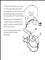
1
USER GUIDE
V-100 / V-200
Welcome
Thank you for making Fishman a part of your acoustic experience. We are proud
to offer you the finest acoustic amplification products available: high-quality
professional-grade tools which empower you to sound your very best.
Troubleshooting
If you are unfamiliar with this product, please pay close attention to the
requirements for installation. Failure to do so can result in permanent damage
to the pickup.
Installation by a qualified professional is strongly recommended.
Technical support, troubleshooting tips and installation information can be found
at http://www.fishman.com/support/
2
Installation
1. Measure the opening of the wing slot on the bridge with a vernier caliper.
The opening should be between .060” and .090” (1.5mm and 2.3mm) for
proper fit.
If the wing slot measures less than .060” (1.5mm), employ a qualified repairman
to enlarge the wing slot.
If the wing slot measures more than .090” (2.3mm), as is the case in violas, a small
wooden shim may be required. If so, use an adhesive to bond the shim to the
“leg” face.
3
2. Slide the V-100 Transducer into the wing
slot of the bridge. Make certain that the
sensing element is in contact with the wing
face and that the spring is in contact with
the corresponding “leg” face of the bridge.
The spring (made of tempered beryllium
copper) provides the proper tension for a
snug fit in wing slots ranging from .060” to
.090” (1.2mm to 2.3mm).
Note: For best performance, the wing
slot opening should be exactly
.070” (1.8mm).
4
3. Jack installation:
For V-100: Once the transducer is
properly installed in the bridge, attach
the output jack to the tailpiece with the
black plastic tie wrap.
For V-200: After fitting the pickup to the
violin, locate the jack to the left of the
chinrest on your violin and tighten it with
the enclosed chinrest key. Be careful not
to scratch the side of your violin.
5
Fine Tuning
Once the pickup is properly mounted, plug the instrument into an amplifier and
play at a low volume. Carefully shift the pickup a small distance within the slot
and test using the trial and error method, listening for the the best location.
Note: If installation is to be permanent, a small drop of adhesive on the side
(lower face) of the transducer can be used.
6
Plugging In
An impedance matching preamp is recommended, but not required. This will
help realize the full frequency response potential of the pickup and allow for
cable runs longer than 10 feet without signal deterioration. Use a high quality,
low capacitance ¼” shielded instrument cable. This will ensure minimal tone
coloration and hum.
7
WWW.FISHMAN.COM
513-300-154 Rev A 4-09