1
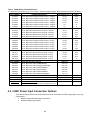
•
Method 1 - Give each mVEC in your vehicle a unique source address base by changing the
source address base value in software, and leave the source address offset (harness address
pins) the same for each. Refer to section 7.1.2.2. Changing the Source Address Base for more
information.
•
Method 2 - Give each mVEC in your vehicle a unique source address offset by configuring the
CAN harness address pins in the CAN connector, and leave the source address base the same
for each. Refer to section 7.1.2.3. Changing the Source Address Offset for more information.
If your system uses more than 8 mVECs, you can combine different source address bases with
different source address offsets to create more than 8 unique CAN source addresses.
7.1.2.1. Viewing the Source Address Base and Source Address Offset
To view an mVEC’s source address base and source address offset
•
Send message ID 0x97 to the mVEC. See Message ID 0x97 (Command) for more details
about the message.
The mVEC responds with message ID 0x97, which displays the current values for the
mVECs source address offset in byte 2.0 and source address base in byte 3.0. See
Message ID 0x97 (Reply).
7.1.2.2. Changing the Source Address Base
•
To set the source address base, set the desired source address base value in byte 1.0 of
message ID 0x90, and send the message to the mVEC. See Message ID 0x90 (Command).
The mVEC responds with message ID 0x01, which indicates if the change was a success or
failure in byte 2.0. See Message ID 0x01 (Reply).
Changes made to the source address base will not take effect until the ignition power to the
mVEC is cycled.
Note: Byte 2.0 in message ID 0x90 is the PGN base value. If you wish to leave the PGN
base value as is, then use 0xFF.
7.1.2.3. Changing the Source Address Offset
The mVEC’s source address offset is assigned by configuring the CAN harness address pins
(called ADDR_0, ADDR_1 and ADDR_2) in the mVEC’s CAN connector. Refer to section 5.1.6.
CAN Connection for more information about connecting and configuring the CAN harness
address pins.
Up to 8 different source address offsets can be created using different combinations of CAN
harness address pin states. There are two CAN harness address pin states: open and
GND_REF.
•
GND_REF indicates the CAN harness address pin is connected to the GND_REF pin on the
CAN connector.
•
Open indicates the CAN harness address pin is open circuit (not connected).
Changes made to the source address offset when the mVEC is powered will not take effect until
the ignition power to the mVEC is cycled.
32


![Hospice Technical Questions & Answers [PDF 114 KB]](http://vs1.manualzilla.com/store/data/005731144_1-513883a519d0031f5bbd9acf18f18865-150x150.png)