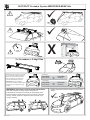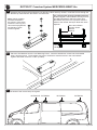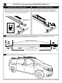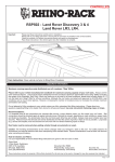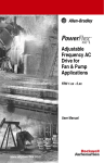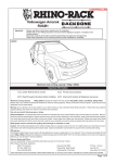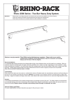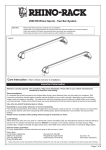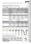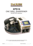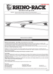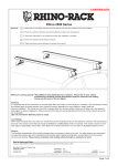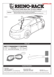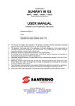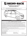
1
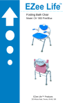
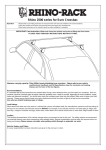
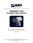
CONTROLLED RLTP/RLTF Crossbar System MERCEDES-BENZ Vito Important: Please read these instructions carefully prior to installation. Check the contents of this kit before commencing fitment and report any discrepancies. Place these instructions in the vehicle’s glove box after installation is complete. Important Information Maximum carrying capacity: 2 Crossbars = 100kg/220lbs evenly distributed over both crossbars. 3-4 Crossbars = 120kg/264lbs evenly distributed over all crossbars. Please refer to your vehicle manufacturers handbook for your vehicles maximum roof loading capacity. Always use the lower of the two figures. When roof racks are to be used in off-road conditions, please build a safety factor of 1.5 into this load limit, 66kg/145lbs for 2 crossbars and 80kg/176lbs for 3-4 crossbars (including the weight of each crossbar assembly, 2.5kg/5.5lbs). Although the roof racks are tested and approved to AS1235-2000, road conditions can be much more rigorous. Do not attempt to fit the crossbars to your vehicle unless you fully understand these fitting instructions. Please direct any questions regarding fitting to the dealer from where the kit was purchased. Use only non-stretch fastening ropes or straps. Recommendations: It is essential that all bolt connections be checked after driving a short distance when you first install your roof racks. Bolt connections should be checked again at regular intervals (once a fortnight is enough, depending on road conditions, usage, loads and distances travelled). You should also check the roof racks each time they are re-fitted. Always make sure to fasten your load securely. Please ensure that all loads are evenly distributed and that the centre of gravity is kept as low as possible. Long loads (e.g. canoes, kayaks, stand-up paddle boards) must be secured front and rear with non-stretch fastening ropes or straps. Roof racks must be removed when putting vehicle through an automatic car wash. Caution: The handling characteristics of the vehicle changes when you transport a load on the roof. For safety reasons we recommend you exercise extreme care when transporting wind-resistant loads. Special consideration must be taken into account when cornering and braking. Note for Dealers and Fitters: It is your responsibility to ensure these fitting instructions are given to the end user or client. Rhino-Rack Australia Pty Ltd 3 Pike Street, Rydalmere, NSW 2116, Australia. Document No: RR111 (Ph) (02) 8846 1900 Prepared By: Kayle Everett (Fax) (02) 9638 4822 Authorised By: Chris Murty http://www.rhinorack.com.au Issue No: 06 Issue Date: 07/09/2015 These instructions remain the property of Rhino-Rack Australia Pty Ltd and may not be used or changed for any other purpose than intended. Page 1 of 7 RLTP/RLTF Crossbar System MERCEDES-BENZ Vito ! ! ! km/h 2 x Crossbars = 5.0kg/11lbs When these roof racks are to be used on a vehicle that is driven off sealed roads, the manufacturer maximum roof load rating (to be found in the vehicles User Manual) should be divided by 1.5. Do not forget to subtract the complete crossbar system weight from your maximum carrying capacity. ? kg 2 Crossbars 100kg/220lbs (Urban Road) = 66kg/145lbs (Off Road) = 80kg/176lbs (Off Road) 3-4 Crossbars 120kg/264lbs (Urban Road) WARNING! Important Load Carrying Instructions With utility vehicles, the cabin and the canopy move independently. Roofracks and vehicle can be damaged if the item transported is rigidly fixed at points on both the cabin and canopy. Instead, rigidly fix to either the cabin roofracks or the canopy roofracks. Page 2 of 7 X Paddle/ Surfboards should be fixed to the front of the vehicle. YES RLTP/RLTF Crossbar System MERCEDES-BENZ Vito Parts List Note: Fit kits (sold as separate) are required to level off 3 and 4 bar systems in both Vortex Aero Bar and Heavy Duty Bar. Refer to the table below for required kits. 13. 4. 10. 9. Vortex 3 Bar 4 Bar VA-FK1 3 4 LHS-A1PAIR 1 1 Heavy Duty 3 Bar 4 Bar LHSPAIR 1 1 Vortex 3 Bar 4 Bar VA150S/B 1500mm 3 4 Heavy Duty 3 Bar 4 Bar RB1500S/B 1500mm 3 4 15. 14. 2. 18. 17. Crossbars: 5. 1. 11. 16. 3. 6. 8. 19. 12. 7. Item Component Part No. RLTFMV04 RLTPMV04 RLTFMV04F 1 M6 x 16mm Button Security Screw B061 4 4 - 2 M6 x 20mm Button Security Screw B062 4 4 - 3 M10 x 25mm Hex Set Screw B071 2 2 2 4 M6 x 40mm Button Security Screw B085 4 4 4 5 M6 x 12mm Button Security Screw B148 4 4 4 6 Vito Front Left Bracket C452 - - 1 7 Vito Front Right Bracket C453 - - 1 8 Vito Bracket C339 2 2 - 9 RLTP Leg M057 - 2 - 10 RLTF Leg M010 2 - 2 11 M6 Nyloc Nut N013 4 4 - 12 M6 Cage Nut N017 4 4 4 13 M10 Channel Nut N024 2 2 2 14 M6 x 12.5mm Flat Washer W003 8 8 8 15 M6 Spring Washer W004 8 8 8 16 M10 Internal Shake Proof Washer W021 2 2 2 17 M10 x 38mm Flat Washer W022 2 2 2 18 M6 x 16mm Flat Washer W031 4 4 - 19 Torque Security Key TORKEY-S 1 1 1 20 Instructions RR111 1 1 1 Tools Required: - 5mm Torque Allen Key, (provided). - Flat Blade Screwdriver. - Tape Measure. - Cleaning Cloth. - 10mm Spanner. Note: All kits are sold as separate. Ensure you have the required kits to complete your fitment. Refer to www.rhino-rack. com.au ‘Fit My Car’ for all Crossbar options. Page 3 of 7 RLTP/RLTF Crossbar System MERCEDES-BENZ Vito 1 Move to the roof of the vehicle. Locate the Plastic Plugs covering the Mounting Points in the roof ditch. Remove the Plugs covering the Points intended to be used (a Flat Blade Screwdriver may be required). Side View: 4 Bars 3 Bars 2 Note Please refer to step 4 for vehicles with through Clean all dirt and debris out of roof ditch with a Cleaning Cloth. 3 hole Mount Points. Butyl Mastic must be applied in this instance to seal against water leaks. If your vehicle has blind threaded holes, Butyl Mastic is not required. Attach the Front Left and Right Brackets. Assemble the M6 Spring and Flat Washers onto the M6 x 16mm Security Screws and insert the Screws though the top of the Bracket as shown. Tighten with the Allen Key provided to 3-4 Nm (2-3 lb/ft). M6 x 16mm Button Security Screw. M6 Spring Washer M6 Flat Washer Rear Inside curve of the Bracket faces in toward roof. Page 4 of 7 Front Note: Vehicle variation has been identified in this vehicle. If the 16mm screws are too long and cannot be fully tightened, use the M6 x 12mm screws supplied. RLTP/RLTF Crossbar System MERCEDES-BENZ Vito 4 Assemble the Spring and Flat Washers onto the M6 x 16mm Security Screws. Insert the Screws though the Bracket top holes and into the bottom mounted holes. For vehicles with through hole Mount Points: Install using M6 x 20mm Button Security Screws Note: Vehicle variation and M6 Flat Washers and Nyloc Nuts. Drop has been identified in the Bracket into place. Fix in position from the this vehicle. If the 16mm inside of the vehicle with Nyloc Nuts and 10mm screws are too long and Spanner. cannot be fully tightened, M6 x 20mm Button use the M6 x 12mm Security Screw. screws supplied. M6 Flat Washer Roof M6 Nyloc 5 6 Place the Vito Brackets onto the roof Mounting Points. Insert the attachment screws into the threaded holes, start the screws. The brackets may have to be lifted to start the screws in the roof brackets. Tighten all bracket screws to 3-4 Nm (2-3 lb/ft). Be aware of the correct setup of Leg Kits. RLTFMV04F RLTPMV04 RLTPMV04 RLTFMV04 Page 5 of 7 RLTP/RLTF Crossbar System MERCEDES-BENZ Vito 7 Place the Legs onto their respective Bracket. Assemble the M6 Spring and Flat Washers onto the M6 x 40mm security bolts. Insert the leg attachment bolts through the leg and into the M6 cage nuts in the bracket. Finger tighten. M6 x 40mm Button Security Screw. M6 Spring Washer M6 Flat Washer Front Bar RLTFMV04F 8 Middle Bar RLTPMV04 Install Leg Height Spacers in the positions shown below to ensure all crossbars are level. 3 Heavy Duty Crossbars 4 Heavy Duty Crossbars N/A 3 Vortex Crossbars 4 Vortex Crossbars Page 6 of 7 Rear Bar RLTFMV04 VAFK1 N/A N/A LHSPAIR N/A N/A LHSPAIR VAFK1 VAFK1 VAFK1, LHS-A1PAIR VAFK1 VAFK1 VAFK1, LHS-A1PAIR RLTP/RLTF Crossbar System MERCEDES-BENZ Vito 9a Heavy Duty Crossbar Install 9b Vortex Crossbar Install Place the crossbar onto the support legs. Push the M10 x 25mm Hex Bolt up and turn the Bolt so that the Channel Nut is located fully across the Crossbar (figure 1.) Finger tighten the crossbar attachment bolts. Locate the Square Nut installed with the Spacer kits into the Crossbar. Finger tighten the M6 hardware. Install Vortex Rubber (cut to length). Install End Caps. Insert End Caps and Rubber. Figure 1. 10 Adjust crossbar overhang to be equal both sides. Tighten M10 Screws for Heavy Duty Bars to 10-11 Nm (7-8 lb/ft). Tighten M6 Screws for Vortex Bars to 4-5 Nm (3-4 lb/ft). EQUAL OVERHANG M10 Hardware (Heavy Duty Bars) M6 Hardware (Vortex Bars) 11 Make sure hardware is secure before use. Page 7 of 7