1
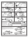
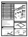
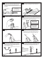
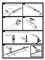
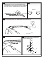
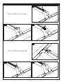
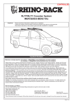
Foton Tunland - Two Bar Trackmount System (RSPT529)
Important:
Please read these instructions carefully prior to installation.
Please refer to your fitting instruction to ensure that the roof racks are installed in the correct locations.
Check the contents of kit before commencing fitment and report any discrepancies
Place these instructions in the vehicle’s glove box after installation is complete.
Important Information
Maximum carrying capacity: 100kg
Recommendations.
It is essential that all bolt connections be checked after driving a short distance when you first install your cross bars. Bolt
connections should be checked again at regular intervals (probably once a week is enough, depending on road conditions,
usage, loads and distances travelled). You should also check the cross bars each time they are refitted. Make sure to fasten
your load securely. Please ensure that all loads are evenly distributed and that the centre of gravity is kept as low as possible.
Use only non-stretch fastening ropes or straps.
Sensitivity to cross winds, behaviour in curves and braking.
The handling characteristics of the vehicle, changes when you transport a load on the roof. For safety reasons, we recommend
you exercise extreme care when transporting wind-resisting loads; special consideration must be taken into account when
braking.
Please remove cross bars when putting vehicle through an automatic car wash.
Load Ratings.
Maximum permissible load is 100kg per pair of cross bars (include the weight of the cross bars, 5kg). When roof racks are to
be used in off-road conditions, please build a safety factor of 1.5 into this load limit. Although the cross bars are tested and
approved to AS1235-2000, Australian road conditions can be much more rigorous. However, increasing the number of cross
bars does not increase the vehicles maximum permissible roof loading.
Note for Dealers and Fitters.
It is your responsibility to ensure instructions are given to the end user or client
Rhino-Rack
3 Pike Street, Rydalmere,
NSW 2116, Australia.
(Ph) (02) 9638 4744
(Fax) (02) 9638 4822
Document No: R413
Prepared By: Kayle Everertt
Issue No: 01
Authorised By: Chris Murty
Issue Date: 10/04/2014
These instructions remain the property of Rhino-Rack Australia Pty Ltd and may not be used or changed for any other purpose than intended.
Page 1 of 8
ü
ü
!
!
!
X
km/h
2 x Crossbars = 5kg
When these roof racks are to be
used on a vehicle that is driven off
sealed roads, the manufacturer
maximum roof load rating (to be
found in the vehicles User Manual)
should be halved. Do not forget to
subtract 5kg from your maximum
carrying capacity due to the weight
of the crossbars and legs.
70kg load rating
(Urban road)
WARNING! Important Load Carrying Instructions
With utility vehicles, the cabin and the canopy move
independently. Roofracks and vehicle can be damaged if the
item transported is rigidly fixed at points on both the cabin and
canopy. Instead, rigidly fix to either the cabin roofracks or the
canopy roofracks.
X
NO
Page 2 of 8
? kg
=
35 kg load rating
(Off road - 70kg / 2)
ü
YES
ü
YES
RSPT529
Parts List
Maximum carrying capacity: 100kg
Item
Component Name
Qty
Part No.
1
Track Mount End Cap FL & RR
2
M215
2
Track Mount End Cap FR & RL
2
M214
3
Foton Tunland Track
2
CA1236
4
Rivet
15
H008
5
Fitting Instruction
1
R413
6
Vortex Generating Strip
5
M626
7a
Sportz Bar Front 901
1
7b
Sportz Bar Rear 859
1
8
M6 x 35mm Button Security Screw
4
B092
8
9
M6 Spring Washer
4
W004
10
M6 x 12.5mm Flat Washer
4
W003
9
10
11
RSP Leg
4
M509
12
Top Pad
4
M173
13
Bottom Pad
4
M172
14
M6 x 16 Dowel Nut
4
N027
15
M6 Dowel Nut Housing
4
A341
16
1/2 x 10G Screw
4
B045
17
Mounting Pad Cover Plate
4
M126
18
Torque Key Small
1
Torkey-S
19
RSP Leg Flap
2
3
6
1
7a,b
A155
19
4
12
16
13
14
18
M183TEXT
Tools Required
Pneumatic or concertina type rivet gun
Marking pen
Power or Cordless drill
5mm drill bit with depth stop
Vacuum cleaner
Cold galvanize & brush
Selleys Butyl Mastic, Caulking Gun
5mm Security Allen key, provided in kit
5/8 or 16mm spanner or socket wrench
Measuring tape
Hacksaw
Flat Head screwdriver
11
17
15
Care Instruction:
Clean vehicle roof prior to fitting Rhino Heavy Duty Racks.
Layout
1
Gently lever the rubber roof trim from the centre with
fingers then starting with a screwdriver (wrap tape around
end of screwdriver to prevent paint scratching) then using
fingertips pull carefully upwards.Small plastic clips are
attached to the roof underneath each end of the strip.
2
Take note of track orientation when placing in the
roof channel. Both tracks are the same.
TOWARDS CENTRE
OF VEHICLE ROOF.
Page 3 of 8
3
Place the track in the channel and measure from
the edge of the windscreen rubber to the front
of the track.The use of masking tape will help
maintain this measurement while marking out holes
for drilling.
FRONT (Dual Cab
�
� measurement shown)
4
Hold track down tight in roof channel. Mark all
holes using a marking pen. Remove the track.
Windscreen Rubber to Track
Measurements
210mm
Dual Cab 210mm
210mm
REAR
5
Accurately centre punch all holes before drilling.
6
Marked out holes can now be drilled through using a
5mm drill bit and drill stop. Set the drill stop to ensure you
don’t drill through the roof lining. Use of a drill stop will
alleviate the need to remove the hood lining.
RDS Drill Stop
Sold Separately
Refer to page 8 for
detailed drilling
instructions
7
Use a vacuum to remove swarf from the roof
channel.
8
Apply a liberal amount of cold galvanize to the
inside and surrounds of all holes. Allow cold
galvanize to dry, then apply a liberal amount of
Selleys Butyl Mastic in and around each hole.
STEP 1.
9
Peel the backing tape off the track. Accurately
place the track over the drilled holes in the roof
channel using the rivets to position. Make sure
track orientation is correct.
TOWARDS CENTRE OF VEHICLE ROOF.
10
STEP 2.
Using either a pneumatic or concertina type rivet
gun, rivet the track into place. Make sure all rivets
are seated firmly onto the base of the track.
NOTE:
Start at the FRONT
and work back so the
track can be pulled
down to follow the
roof curve.
FRONT
Page 4 of 8
11
Push the Dowel Nut into the Dowel Nut Housing
with the thread facing up through the hole. Slide
the unit into the top ‘U’ section of the track.
12
Insert the Sportz leg fully into the cross bars, a
rubber mallet may be required to knock the leg in
place.
Dowel Housing sits
between this section.
Slide Dowel Nut
into Housing.
13
15
From the underside of the cross bar insert the
Phillips head screw.
14
Insert the rubber buffer strip into the top of the
crossbar.
Place the bottom pad over the Dowel Nut Housing then Top Pad. Sit the Leg/Cross bar assembly on the Top
Pad. Place the M6 Security Screw and washers through the hole in the Leg as shown and screw into the Dowel
Nut. Tightening torque is 3-4Nm. Tighten after positioning both sides equally.
Tangs face towards
outside of vehicle
16
Repeat steps 11 - 16 for the other crossbar assembly. The Front and Rear bars should be 830mm apart centre
to centre, 215mm back from the front of the track.
830mm
Front of
Vehicle
215mm
Be sure not to mount the legs
over any cut outs on the track.
Page 5 of 8
18
Measure and cut the rubber roof trim and put back in the vehicle roof
channel at the front and rear ends of the Track. The front piece needs
to be measured so the end of it sits under the windscreen rubber.
The measurement and cutting of the rubber roof trim isn’t critical since
the End Cap will cover it. Recommend using a fine tooth hacksaw
because of metal inside the rubber roof trim. A windscreen adhesive is
recommended to hold this roof trim in position.
19
Showing the orientation of the
end caps after installation. Caps
are LEFT and RIGHT handed..
FRONT VIEW
Cut trim 5-10mm from
end of Track.
Rear of vehicle
20
When front and rear cross bars are in required position, tighten legs and cross bars.
22
Check racks are secure before loading and driving.
23
When the cross bars and legs are removed the
roof pads can be covered for protection with the
Mounting Pad Cover Plates.
7
8
9
17
12
Page 6 of 8
How to use the accessory flap
1
How to OPEN the accessory flap
Remove crossbar rubber.
2
3
Lift flap.
Push flap down to allow hardware to slide into C channel.
1
How to CLOSE the accessory flap
Re-fit flap using security Allen key.
2
Re-insert Vortex rubber Strip.
3
Page 7 of 8
Foton Tunland - Two Bar Trackmount System (RTS529)
Optional Rhino Drill Stop (RDS) sold separately
1
2
Drill Stop
6mm
Warning!
MAXIMUM Drill Depth is 6mm.
Drill approximately halfway and then use a vacuum
to remove swarf from roof channel. Continue drilling
the hole, repeat operation for remaining holes.
3
5
4
3
2
1
FRONT
OF CAR
Page 8 of 8
6
7