1
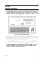
Section 7
Normal Operation
The optional Model 5230 Remote Annunciator provides annunciation of trouble and alarm
conditions, and can be used to program the system. Key functions for both the Model 5230
(Figure 7-1) and the 5204 built-in touchpad (Figure 7-2) are described in Section 7.1. Section
8 explains how to program the 5204 using the Model 5230.
Figure 7-1 Model 5230 Remote Annunciator
The Model 5230 Remote Annunciator has a liquid crystal display (LCD) for displaying
English-language messages. If the 5204 is not being programmed, the LCD cycles through all
messages that are applicable at the time, showing a different one every 1.5 seconds. Refer to
Section 9.3 for more information on troubleshooting messages.
When AC power is being supplied, and the battery is fully charged, the POWER LED glows
steadily. If the POWER LED is flashing, the AC power has been removed or the backup
battery is low. If neither AC nor battery power is being supplied, the POWER LED is off.
The audio transducer buzzer produces short beeps to annunciate keystrokes. It also emits a
long, high-pitched tone to denote a trouble condition or to indicate that an annunciator
function has been entered incorrectly (see Section 7.1).
150644
7-1
Model 5204 Fire Control/Communicator Installation Manual
Figure 7-2 Built-in Touchpad
7.1
Built-in Touchpad and Model 5230 Annunciator
Operation
To operate the 5204, you must use either the built-in touchpad or the Model 5230 Remote
Annunciator. This annunciator functions the same as the internal touchpad except for the
STEP key. The installer uses this key to step through programming options (see Section 8.3).
Following are the basic operating functions. Note that if no keys are pressed for 15 minutes
while in program mode, the system will time out and resume normal operation.
The message TRY AGAIN appears on the 5230 display if you do not press any keys for 5
seconds while accessing a function, or, if you attempt to access a function before exiting from
another function.
In the following table, Code 0 refers to the installer’s code (factory programmed as 5204).
Code 1 refers to the operator’s code (factory programmed as 1111). These two codes are
described in Step 45 and Step 46 of Step Programming (see Section 8.4.1).
7-2
150644
Normal Operation
Note: A valid operating code is always required when using the 5230.
Table 7-1: Touchpad Operations
Press:
To:
Additional Information
5230 Annunciator
Built-in Touchpad
Clear
CLEAR
Enables you to start again if you
enter the wrong keystrokes. If you
enter a function incorrectly on the
5230, the annunciator’s PZT
buzzer will emit a long, highpitched tone.
CLEAR
Test the system
TEST
ENTER
0
Reset alarms
(or smoke
detectors)
RESET
ALARM
1
ENTER
TEST
+ code 0 or 1
0
+ code 0 or 1
RESET
ALARM
1
The system will test the 4180
outputs, the built-in touchpad LED
display, signaling devices, sirens,
and communicator.
ENTER
ENTER
+ code 0 or 1
After a smoke alarm has been
triggered, this function removes
smoke detector power for the
programmed length of time (as
determined by the smoke
detector). This allows the smoke
detector to sense new alarm
conditions.
When a trouble condition occurs and you reset the alarm, the trouble condition is stored in memory until you clear the alarm
memory. If you do not clear the alarm memory, the trouble condition is displayed the next time a trouble condition occurs,
implying incorrectly that more than one trouble condition exists.
Clear alarm
memory
CLEAR
MEMORY
ENTER
2
Reset the dialer
DIAL.
RESET
ENTER
3
CLEAR
MEMORY
+ code 0 or 1
ENTER
Aborts an in-progress call to the
central station.
2
DIAL.
RESET
+ code 0
ENTER
Clears all data out of alarm
memory and resets the 4180.
(This function removes all
memory of alarms.)
+ code 0
3
Initiate download
LOAD
ENTER
4
Display alarm
memory
DISPLAY
MEMORY
ENTER
5
Display troubles
DISPLAY
TRBL.
ENTER
6
Silence trouble
or alarm conditions
150644
SILENCE
STEP
LOAD
+ code 0
+ code 0 or 1
ENTER
5
DISPLAY
TRBL.
+ code 0 or 1
+ code 0
4
DISPLAY
MEMORY
+ code 0 or 1
ENTER
Starts the downloading process.
Exit the DOWNLOADING mode
by pressing CLEAR CLEAR.
Displays the current alarm
memory. (It is recommended that
you clear alarm memory after
displaying it.)
Displays trouble conditions.
ENTER
6
SILENCE
Silences signaling devices that
are in trouble or alarm. (Onboard beeper and local annunciators continue to sound until
serviced. See Section 9.1 for
more details.)
7-3
Model 5204 Fire Control/Communicator Installation Manual
Table 7-1: Touchpad Operations
Press:
To:
Additional Information
5230 Annunciator
Fire drill
CLEAR
MEMORY
TEST
CLEAR
MEMORY
ENTER
+
0
2
Built-in Touchpad
2
code 0 or 1
TEST
ENTER
+ code 0
0
Causes the system to sound an
alarm and report a FIRE TEST.
To end a fire drill:
To end a fire drill:
SILENCE
SILENCE
STEP
Set time
SET
TIME
+ code 0 or 1
Enter time in military time..
SET
TIME
ENTER
9
ENTER
9
The SET MODE LED will turn on and the built-in touchpad display will flash 9- indicating that you are in the
SET TIME mode.
Note: The 5204 powers up in the SET TIME mode, with 9- showing on the display. If you wish to set the
time at this point, it is not necessary to press the 9 ENTER (code) key sequence. Simply key in the appropriate
digits. To exit the SET TIME mode, press ENTER.
Disable/Enable
(shunting / unshunting)
Note:
(Zone #1-4) +
code 1 or 0
DISABLE
SHIFT
+
DISABLE
(Zone #1-4) +
1 or 0
Disables a zone (prevents it
+ code from responding to an alarm
condition) or reactivates a disabled zone. When you disable,
a trouble buzzer will sound.
If the dialer is busy, modes 22, 25, and 27 are disabled.
If you are in mode 22, 25, or 27, the dialer is disabled.
Walk test
CLEAR
CLEAR
MEMORY MEMORY
Zone Troubleshooting mode
CLEAR
CLEAR
MEMORY MEMORY
ENTER
ENTER
+
code 0 (factory programmed
as 5204)
+ code 0
(factory programmed as
5204)
To exit press:
To exit press:
2
2
SILENCE
STEP
SILENCE
STEP
CLEAR
CLEAR
CLEAR DISPLAY
MEMORY MEMORY
2
2
2
SILENCE SILENCE
CLEAR
CLEAR
.
Enables you to test the system.
When you enter this mode, the
LCD will indicate that you are
in the Walk Test mode. When
a zone is violated, the signaling
device outputs will become active for approximately 6 seconds.
.
CLEAR DISPLAY
MEMORY MEMORY
ENTER
+
5
code 0
2
ENTER
+ code 0
5
To exit press:
Enables you to locate and correct problems. The use of this
mode is described in Section
9.2.2.
To exit press:
SILENCE SILENCE
7-4
SILENCE
STEP
SILENCE
STEP
CLEAR
CLEAR
CLEAR
CLEAR
.
.
150644
Normal Operation
Table 7-1: Touchpad Operations
Press:
To:
Additional Information
5230 Annunciator
Step Programming mode
CLEAR
MEMORY
2
Built-in Touchpad
CLEAR
MEMORY
ENTER
+
7
code 0
2
ENTER
+ code 0
7
To exit press:
To exit press:
SILENCE SILENCE
7.1.1
SILENCE
STEP
SILENCE
STEP
CLEAR
CLEAR
CLEAR
CLEAR
Enables you to program 5204
options stored on the EEPROM. Refer to Section 8.3
for instructions on using mode
27.
.
.
Operating Modes
The following table describes which codes can access operating modes during alarms:
Operating Mode
Allowed
During
Alarm
Code Required
On 5230
On Built-in Touchpad
00
System test
No
Code 0 or 1
None
01
Reset alarm
Yes
Code 0 or 1
Code 0 or 1
02
Clear alarm memory
No
Code 0 or 1
None
03
Dialer reset
Yes
Code 0
Code 0
04
Download
No
Code 0
Code 0
05
Display alarm memory
No
Code 0 or 1
None
06
Display troubles
No
Code 0 or 1
None
09
Set time
No
Code 0 or 1
Code 0 or 1
2B
Silence mode
Yes
Code 0 or 1
None
20
Fire drill
No
Code 0 or 1
Code 0 or 1
22
Walk test
No
Code 0
Code 0
27
Program
No
Code 0
Code 0
25
Troubleshooting
No
Code 0
Code 0
E0
Disable/enable zone
Yes
Code 0 or 1
Code 0 or 1
7.1.2
Built-in Touchpad Display Codes
The built-in touchpad display shows the zones in which a trouble or alarm condition is
occurring. It also displays two-digit codes that represent a variety of conditions, as an aid in
troubleshooting the system. These codes are listed below.
150644
7-5
Model 5204 Fire Control/Communicator Installation Manual
The following table describes the codes that appear on the built-in touchpad:
Display
0
1 through 4
Fire drill (with ALARM, ALARM MEMORY, or TROUBLE LED).
Zone numbers (with ALARM, ALARM MEMORY, or TROUBLE LED).
A “c” in front of the number indicates a supervisory sprinkler zone.
E7
Indicates trouble with the EEPROM memory.
F0
F1 through F3
5230 annunciator power trouble.
Indicates trouble with a particular annunciator.
A1 through A2
Indicates trouble with a particular bell output.
P3
P3 indicates a short between Earth Ground and Common Ground. To determine the
location of the short, remove field wiring circuits until the control returns to normal
operation. See Section 9.2.
P4
P4 indicates a short between Earth Ground and loop or bell power. To determine the
location of the short, remove field wiring circuits until the control returns to normal
operation. See Section 9.2.
P0
Indicates that the printer is out of paper.
dc
Ac
dF
Low battery condition.
Low AC condition.
Dialer failed to communicate or Data lost during an attempt to transmit data to the
central station.
L1
L2
Phone Line 1 Fault
Phone Line 2 Fault
-0
-2
-4
-5
-6
-7
-8
-9
Fire drill
Walk test
Downloading
Zone test
HEX PROGRAMMING mode
STEP PROGRAMMING mode
SET DATE mode
SET TIME mode
2-, 3-, 4-, 5-, 6-, 7-, 8-, 9-
7-6
Explanation
User must enter a code to perform the desired function with these prompts.
150644
Normal Operation
7.1.3
Silencing the System
To silence a trouble, press SILENCE.
To silence an alarm, follow these steps:
1. Disable the zone by pressing (zone number) + DISABLE + code 1 or 0.
2. Reset the system by pressing
RESET
ALARM
1
ENTER + code 1 or 0.
3. The zone is now in trouble because of the disabled zone and can be silenced in the normal
way by pressing SILENCE.
See Section 9.1 for related information.
7.1.4
LED Indicators
Six light emitting diodes (LEDs) appear in the 5204 cabinet window.
LED
ALARM (red)
SILENCED (yellow)
AC / DC (green)
MEMORY (yellow)
TROUBLE (yellow)
SET MODE (yellow)
REPORT
150644
Status
Condition
OFF
No alarm condition exists.
ON
A fire alarm condition exists in the zones shown on the
touchpad.
OFF
An alarm or trouble has not been silenced.
ON
An alarm or trouble condition exists and the audible
annunciators have been silenced.
OFF
Panel has lost all power.
ON
Panel is running on AC and battery power (normal
condition).
FLASHING
Panel is running on battery power only or AC power only.
OFF
No information is stored in alarm memory.
ON
An alarm condition has been reset.
OFF
No trouble condition exists.
ON
A trouble condition exists.
OFF
Normal operating mode and not reporting.
ON
System is in a SET (TEST or PROGRAM) mode.
FLASHING
System is reporting
7-7
Model 5204 Fire Control/Communicator Installation Manual
7.2
System Testing
System testing includes fire drills, zone testing, and 24-hour automatic tests.
7.2.1
Fire Drills (Mode 20)
You can run fire drills using either the built-in touchpad or the Model 5230 touchpad. To
CLEAR
MEMORY
TEST
0 ENTER + code 0 or 1. The system will sound an alarm
2
initiate a fire drill, press
and report a fire test. To end the fire drill, press SILENCE) + code 0 or 1.
7.2.2
Walk Test (Mode 22)
The Walk Test mode enables you to test individual sensors.
CLEAR
CLEAR
MEMORY MEMORY
2
2 ENTER + code 0 (factory-programmed as
To enter the Walk Test mode, press
5204). The LCD will indicate that you are in the Walk Test mode. When a zone is violated,
the bell outputs will become active for approximately six seconds. During a walk test, smoke
verification is disabled. Follow the manufacturer’s directions for testing smoke and heat
detectors. To violate a waterflow detector, open the waterflow valve.
Zones can be disabled individually to facilitate testing and troubleshooting. Disabled zones
will NOT be tested. If no zones are tripped during the Walk Test (or keys pressed) for 15
minutes, the system will time out and resume normal operation.
To exit Walk Test mode, press STEP STEP CLEAR CLEAR. If using the built-in touchpad,
press SILENCE SILENCE CLEAR CLEAR.
7.2.3
Automatic Self Test
The Model 5204 lets you select the time of day to send the 24-hour automatic test signal to the
central station.
The Auto Test (Dialer test sent automatically at specified times) also sends all unrestored
events, as now required by UL. Events listed before AUTO TEST on the printout at the
central station are new events. Events listed after AUTO TEST are old events that have not
been restored.
7.2.4
Watchdog Circuit
During normal operation, the control microprocessor of the 5204 is constantly running
programs to check inputs and carry out other routine functions. If this program stops running
for some reason, the watchdog circuit will automatically attempt to resume normal operation
by resetting the microprocessors. Each time the watchdog circuit initiates a reset signal, it
will also sound the audible trouble signal for approximately four seconds.
7-8
150644