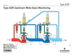
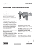
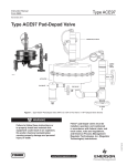
1
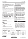
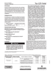
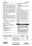
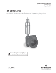
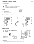
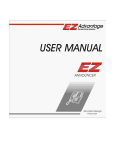
Bulletin 75.1:RF100 February 2006 RegFlo™ RF100 Series Pressure and Flow Instruments W8196 W8162 TYPE RF110 PRESSURE INSTRUMENT TYPE RF100 FLOW AND PRESSURE INSTRUMENT MOUNTED ON TYPE EZR REGULATOR W8379 • Flow Estimation TYPE RF100 FLOW AND PRESSURE INSTRUMENT MOUNTED ON A TYPE 1098-EGR REGULATOR New and Improved • New Algorithms • Improved Modem • Pressure Recorder • Inches w.c. Sensor • User Level Security • Extended Battery Life • More Mountings Available • Economical Flow Data • Expanded History Capacity • Low Power Consumption • Host and Local Communications • Type EZR or 1098-EGR Retrofit Capability • Metric Configuration Available • One Second Sample Rate Available US Patent Number 6441744 Other US and Foreign Patents Pending www.emersonprocess.com/regulators D102790X012 Benefits • Data Archive Bulletin 75.1:RF100 Introduction RegFlo™ RF100 Series pressure and flow instruments are devices which measure and archive flow and pressure data. Other parameters such as battery voltage, and minimum and maximum values are also stored. Alarms may be configured to signal abnormal or emergency conditions. The Type RF110 instrument is used as a stand-alone pressure instrument. Mounted on a regulator, such as the Type EZR or 1098-EGR, the Type RF100 instrument measures pressure and also estimates flow rates based on valve plug travel. Features • Flow Estimation—The RegFlo™ Type RF100 instrument estimates the flow rate through the regulator by measuring inlet pressure, outlet pressure and the valve plug travel of the Type EZR or 1098-EGR. The device stores these estimates in a time stamped history file. The accuracy is within ± 10% of actual flow. • Type EZR or 1098-EGR Retrofit Capability—The Type RF100 instrument can be field mounted to the bonnet of an existing Type EZR or 1098-EGR regulator. The Type EZR or 1098-EGR travel indicator or indicator plug is replaced with the Type RF100 instrument assembly. • Low Power Consumption—The RF100 Series electronics and firmware are designed for minimal power consumption. This allows the device to battery powered. External power may also be applied from a power supply or solar panel. • Extended Battery Life—Over 2 year battery life when set for one minute sample intervals and a five minute modem connection per day. • Configurable Sample and Log Intervals—The RegFlo instrument may be configured to meet specific customer requirements. The Sample Interval sets the frequency for measurements. The Log Interval sets the rate of recording data to the history file. • Data Archive—RegFlo instruments record data in a daily log at a specified log interval. Average, minimum, and maximum values are recorded for the pressure and flow inputs. Other records for battery voltage and board temperature are also stored. The RegFlo instrument stores 35 days of daily records and 840 logs for the log interval rate. 2 RegFlo Type RF100 Flow and Pressure Instrument Mounted on a Type EZR Pressure Reducing Regulator • Expanded History— Additional file maintains 8640 logs for the log interval rate. • Low Pressure Sensor—0 to 30-inches w.c. (0 to 75 mbar) range with accuracy of 1.5% of span. • User Level Security—The RegFlo instrument allows the user to specify a user name, password, and access level for up to fifteen different users. The access level controls who is allowed access to menus and screens in the RegLinkTM software. • Alarms—Alarms can be configured in the RegFlo instrument to trigger abnormal conditions for each of the sampled parameters. High and low alarm conditions are available. Alarms are stored in the alarm log. The RegFlo instrument will store the last 240 alarm logs. Each alarm may also be set for Spontaneous Report by Exception. Bulletin 75.1:RF100 Benefits • Easy Integration— The data acquired by the RegFlo instrument can be easily integrated into existing Supervisory Control and Data Acquisition (SCADA) systems with the use of ROC or Modbus protocols. • Time Stamped Data— Records regulator station parameters to help troubleshoot station performance problems. • Economical Flow Data—No requirement for expensive metering equipment. • Verify and Calibrate Model—Flow and pressure data from the RegFlo instrument can be used to verify and calibrate assumptions used to develop the model. Confidence in the model output is improved. RegFlo Type RF110 Pressure Instrument • Metric Units—Instrument can be configured to record pressures in kPa or bar and flow in Nm3/h. • Local Communications—The RegFlo instrument includes a Local Operator Interface (LOI) port for interface to the RegLink™ software with a personal computer (PC). • Increased Sample Rate—Selection provided for one second sample interval. • Logic Alarms—Logic alarms provide a mechanism to link multiple parameters together in a single alarm. Travel, pressures, and flow conditions may be combined to trigger conditions such as shutoff problems or monitor override control. • Pressure Recorder—The Type RF110 instrument is an Electronic Pressure Recorder. It can measure and record up to three different pressures. • New Modem Communications— Modem available to receive communications full time and maintain 27 month battery life. • Asset Management—Better information contributes to greater system efficiency, productivity and optimization. • Comparison—The data acquired can be used to compare customer demand on the system over certain time periods. Provides the ability to disclose areas that are at or near full capacity. • Defer Capital Expenditures—The data provided by the RegFlo instrument may enable companies to reduce or delay major capital expenditures, such as pipeline construction. • Host Communications—The RegFlo instrument supports two communication ports that can be used for host communications. These host ports support communication based on ROC and Modbus protocols. • Safety and Integrity—Report by exception and other alarm capabilities help ensure the health of the system. 3 Bulletin 75.1:RF100 Specifications Available Configurations Type RF100: Flow and Pressure Instrument measures valve plug travel, inlet pressure, and outlet pressure when mounted on a Type EZR or 1098-EGR Type RF110: Pressure Instrument is used as a stand-alone pressure recorder Diagnostics Board Temperature, Power Input, Logic/Battery Voltage Security 15 users with passwords and 3 levels of access Communication Ports Operator Interface: RS-232 (RX, TX, RTS); ROC protocol only COM1: RS-485; ROC and Modbus protocol COM2 (Optional): RS-232 or V-22 BIS Modem; ROC and Modbus protocol Alarms • Hi, Hi/Hi, Low, and Low/Low, on all analog inputs • Logic alarms • 240 logs in alarm log Sensor and Pressure Ranges(1) See Table 1 Instantaneous Flow Estimation Accuracy See Tables 2 and 3 and the Instantaneous Flow Estimation Accuracy section. Log Interval LOG INTERVAL, MINUTES STANDARD HISTORY CAPACITY, DAYS (840 LOGS STORED, ALL VERSIONS) EXTENDED HISTORY CAPACITY, DAYS (8640 LOGS STORED, AVAILABLE ONLY FOR FIRMWARE VERSION 2 AND HIGHER) 1 2 3 4 5 6 10 12 15 20 30 60 0.6 1.2 1.8 2.3 2.9 3.5 5.8 7.0 8.8 11.7 17.5 35.0 6 12 18 24 30 36 60 72 90 120 180 360 Daily Log 35 days of daily values (average, accum, min/max) Sample Intervals 1, 10, and 30 seconds; 1, 2, 5, 10, and 30 minutes Processor Memory Flash: 128 Kbytes EEProm: 32 Kbytes Static RAM: 128 Kbytes Power Battery Input: 3.6 Vdc Input Power: 10 to 28 Vdc Battery Information Lithium Ion, 3.6 Vdc, 19.0 amp-hours Real Time Clock • Hr:Min:Sec • Day:Month:Year • Battery Backed Environmental(1) Operating Temperature: -40° to 167°F (-40° to 75°C) Storage Temperature: -58° to 185°F (-50° to 85°C) Operating Humidity: 5% to 95% non-condensing Vibration: Meets SAMA PMC 31.1 Electromagnetic Interference: Designed to meet requirements of IEC 61326 Electrical Equipment for Measurement, Control, and Laboratory Use Radiated Emissions: FCC Part 15 Class A Approvals CSA Class I, Division 1, Explosion-Proof, Gas Groups C and D; Class I, Division 2, Nonincindive groups C and D; Certified to Canadian and U.S. Standards Construction Pressure Sensor Body: S31600 Stainless steel Housing and Cap: Die-cast aluminum alloy with iridite plating and paint Exposed Bar Parts: S31600 Stainless steel Pipe Plug: Plated steel Connections Electrical: Housing has 2-1/2-inch 14 NPT conduit connections for wiring Process: Sensors have 1/4-inch 18 NPT process connections Vents: Vent connections are tapped with 1/4-inch 18 NPT threads for use with piping in pit installations Weight Type RF100: 1 or 2-inch (DN 25 or 50): 7.8 pounds (3,54 kg) 3 or 4-inch (DN 80 or 100): 8.0 pounds (3,63 kg) 6-inch (DN 150): 9.0 pounds (4,08 kg) Type RF110: 7.0 pounds (3,18 kg) 1. The pressure/temperature limits in this bulletin or any applicable standard limitation should not be exceeded. 4 Bulletin 75.1:RF100 Table 1. Sensor and Pressure Ranges, and Accuracy ACCURACY, % OF SPAN SENSOR RANGE, PSIG (bar) 0 to 30-inches w.c. 0 to 15 0 to 35 0 to 100 0 to 300 0 to 500 0 to 1000 0 to 1500 -4° to 122°F (-20° to 50°C) -40° to 167°F (-40° to 75°C) MAXIMUM OPERATING PRESSURE, PSIG (bar) MAXIMUM EMERGENCY PRESSURE, PSIG (bar) 1.5 0.5 0.5 0.5 0.5 0.5 0.5 0.5 2.5 1.0 1.0 1.0 1.0 1.0 1.0 1.0 9 (0,62) 45 (3,10) 85 (5,86) 185 (12,8) 585 (40,3) 985 (67,9) 1500 (103) 1500 (103) 300 (20,7) 475 (32,8) 475 (32,8) 475 (32,8) 1500 (103) 1500 (103) 1500 (103) 1500 (103) (0 to 75 mbar) (0 to 1,03) (0 to 2,41) (0 to 6,90) (0 to 20,7) (0 to 34,5) (0 to 68,9) (0 to 103) Table 2. Type 1098-EGR Instantaneous Flow Estimation Accuracy PERCENTAGE OF ACTUAL FLOW CAGE TYPE For 5 to 10% of Travel ± 30 ± 20 Linear or Quick Opening Whisper Trim® For 10 to 20% of Travel For 20 to 30% of Travel For 30 to 40% of Travel For 40 to 100% of Travel ± 20 ± 15 ± 10 ± 10 ± 17.5 ± 15 ± 10 ± 7.5 Note: The accuracy of the flow estimation is dependant on pressure drop and pressure sensor range. Table 3. Type EZR Instantaneous Flow Estimation Accuracy 100 95 90 PERCENTAGE OF ACTUAL FLOW 3 and 4-Inch (DN 80 and 100) For 20 to 30% of Maximum Flow For 30 to 100% of Maximum Flow For 20 to 30% of Maximum Flow For 30 to 100% of Maximum Flow 17E97 Nitrile ±15 ±10 ±20 ±10 17E67 Nitrile ±20 ±15 ±20 ±15 80 75 PERCENT FLOW DIAPHRAGM MATERIAL 2-Inch (DN 50) 85 70 65 60 55 50 45 40 35 30 25 20 15 10 5 0 0 5 10 15 20 25 30 35 40 45 50 55 60 65 70 75 80 85 90 95 100 PERCENT TRAVEL - - - Linear Cage Principle of Operation The main function of RegFIo RF100 Series instruments is the acquisition and storage of pressure, travel, and flow data from the regulator installation. It also provides alarm and diagnostic functions relative to pressure, travel and flow. The flow algorithm uses upstream and downstream pressure measurements along with travel to calculate an instant and accumulate flow rate. The travel and pressure sensors are integral to the module. It is also available with an optional third pressure sensor. The module may also be mounted remotely and used only to monitor line pressures. Data storage will be provided in the unit. That data may be accessed via a local interface or remotely. The remote connection may be via dial-up phone or radio. The communications ports will support ROC and Modbus protocols. The unit is designed to meet Class 1 Division 1 explosion proof requirements and be submersible. It is DC powered by an internal battery or external source. Quick Open Cage Whisper Cage Figure 1. Typical Flow Characteristic of the Type 1098-EGR Type RF100 Flow and Pressure Instrument The Type RF100 instrument measures valve plug travel, inlet pressure, and outlet pressure. A third pressure sensor is available as an option to measure an auxiliary pressure. An algorithm estimates the flow through the regulator and archives pressure, travel, and flow data in the history log. It also records other parameters such as battery output, minimums and maximum values, etc. Alarms may be configured to signal abnormal or emergency conditions. The Type RF100 flow and pressure instrument is available for the 1, 2, 3, 4, and 6-inch (DN 25, 50, 80, 100, and 150) Type EZR and the 2, 3, 4, and 6-inch (DN 50, 80, 100, and 150) Type 1098-EGR body sizes. The flow estimation is not available for the 1-inch (DN 25) Type EZR. It is also not available for the 6-inch (DN 150) Type EZR when the differential pressure exceeds 175 psi (12,1 bar). 5 Bulletin 75.1:RF100 Type RF100 Pressure and Travel Indication The Type RF100 instrument is available for the 1, 3, and 6-inch (DN 25, 80, and 150) Type EZR body sizes as a pressure and travel indicator. The instantaneous flow estimation capability for these sizes is currently not available. Instantaneous flow estimation capability will be added when development of the required Flow Estimation Algorithm is completed. A field installable software update will be available to add the Flow Estimation Algorithm. The unit will not have to be removed from its installation to install the update. Until the software update is installed, the instrument will display the value of zero for the Estimated Flow, Accumulated Flow, and Accumulated Travel values. Instantaneous Flow Estimation Accuracy Type EZR The instantaneous flow estimation accuracy of the RegFlo Type RF100 instrument is related to the percentage of flow through the Type EZR regulator. As the flow rate through the regulator increases, the instrument’s flow estimation becomes more accurate. The typical flow estimation accuracy for each Type EZR body size is shown in Table 3. Note The percent of flow is not equivalent to percent of travel. The Type EZR regulator does not exhibit a linear valve characteristic. The regulator in most cases will not start to flow through the main valve until the percentage of travel reaches 10% of full open. Refer to the Type EZR Bulletin, 71.2:EZR (D102626X012) capacity tables for the maximum flow of the regulator. The maximum flow is related to inlet pressure and outlet pressure of the regulator. Field data shows that the RegFlo Type RF100 has the ability to estimate hourly flow rates within ± 5% of the actual flow and daily rates within ± 2% of the actual when the Type EZR regulator is operating at or above mid-range of capacity. Type 1098-EGR The instantaneous flow estimation accuracy of the RegFlo Type RF100 instrument is related to the percentage of travel through the Type 1098-EGR regulator. As the flow rate through the regulator increases, the instrument’s flow estimation becomes 6 more accurate. The typical flow estimation accuracy for each Type 1098-EGR cage is shown in Table 2. The accuracy is improved at higher pressure drops. The data in Table 3 is representative of a 5 to 10 psi (0,34 to 0,69 bar) pressure drop. Accuracy of the pressure sensor at lower pressure drops also has an impact. The relationship of flow to travel is dependent on the main valve cage type used. Figure 1 shows the typical characteristic (flow vs. travel) for each cage type. Type RF110 Pressure Instrument The Type RF110 instrument is used as a stand-alone pressure recorder. It is the same as the Type RF100 instrument except it is mounted remotely from the regulator and does not measure regulator travel or estimate flow rates. Pressures are piped to the unit and are measured and archived in the history log. Other parameters such as battery output, and minimum and maximum values are also stored. Alarms may be configured to signal abnormal or emergency conditions. Configuration Parameters Sample Interval The Sample Interval is how often a sample is taken of Analog Input values. The RegFlo instrument electronics will go into a low power mode between samples. This allows the power consumption to be minimized. The more frequently the RegFlo instrument samples the Analog Inputs the more power is consumed, or the shorter the battery life. The default Sample Interval is 1 minute. See Table 3 to determine power requirements for the device. The following selections for Sample Interval are provided: • 1 second • 2 minute • 10 second • 5 minute • 30 second • 10 minute • 1 minute • 30 minute Periodic Log Interval The Log Interval is the rate sampled values are logged to the History log. For example, if a 60 minute Log Interval is selected, the History log will include a log record for every 60 minute interval. The selection of Log Intervals influences the memory capacity of the History log. The History log will store 840 of the most current records. See the Specifications section on page 4 for further information. The following selections for the Periodic Log Interval are provided: • 1 minute • 10 minute • 2 minute • 12 minute Bulletin 75.1:RF100 • • • • 3 minute 4 minute 5 minute 6 minute • • • • 15 minute 20 minute 30 minute 60 minute Log intervals for the Extended History log include the above plus 10, 20, and 30 seconds. Regulator Parameters (Type RF100 only) The flow calculation requires the user to configure parameters relative to the regulator type, size, material, and construction. Other parameters, such as specific gravity and temperature of the gas must also be specified. The user has the option to use a different temperature for each month of the year. The user may also configure the type of regulator installation. The Installation Type is used for setting the default Logic Alarms. The Installation Types are defined in the following paragraphs: Single Cut (2 or 3 sensors)—Refer to Figure 2A on page 8. The Type RF100 instrument is installed on a single pressure cut and the unit is measuring the inlet and outlet pressure of the regulator. An optional third pressure sensor could measure another pressure at the installation. Upstream RegFlo Instrument (3 sensors)—Refer to Figures 2D and 2E on page 9. In an Downstream Wide-Open System it is recommended that the Type RF100 instrument be installed on the working (upstream) regulator. In a Working Monitoring System the Type RF100 instrument may be installed on either regulator. In this type, it is installed on the upstream regulator. The inlet pressure (P1) sensor is monitoring the station inlet pressure and the outlet pressure sensor (P2) is monitoring the pressure between the two regulators (intermediate pressure.) The auxiliary (P3) sensor is monitoring the station outlet pressure. Custom—Any other installation type not defined above. This selection will clear all of the default Logic Alarms. Communication Ports The RegFlo instrument communication ports provide a data link to the RegLink software and host systems. Available Comm Ports are as follows: • Local Operator Interface (LOI)—EIA-232 for use with RegLink (Standard) • COM1 (Host)—EIA-485 Serial Communications (Standard) • COM2 (Host)—Dial up modem or EIA-232 Serial Communications (Optional) Downstream RegFlo Instrument (2 sensors)—Refer to Figures 2B and 2C on page 8. In an Upstream Wide-Open System it is recommended that the Type RF100 instrument be installed on the working (downstream) regulator. In a Working Monitoring System the Type RF100 instrument may be installed on either regulator. In this type, it is installed on the downstream regulator. The inlet pressure (P1) sensor is monitoring the pressure between the two regulators (intermediate pressure) and the outlet pressure sensor (P2) is monitoring the station outlet pressure. The Local Operator Interface port supports Fisher ROC protocol. The Host ports support Fisher ROC and Modbus protocols on the same channel. Refer to the RegLinkTM Software User Manual (Form 5669, PN D102780X012) for further information. Downstream RegFlo Instrument (3 sensors)—This is the same as the Downstream RegFlo Instrument (2 sensors) with the additional auxiliary (P3) sensor monitoring the station inlet pressure. The RegFlo instrument supports Modbus Function Codes 3 and 16 over communications ports COM1 and COM2. All RegFlo values are read or written as Floating-point values. See Table 4 for the default assignments and descriptions for Function Code 3. For further details of the Modbus functionality, refer to the RegLink Software User Manual (Form 5669, D102780X012), September 2005. Table 4. Modbus Register Assignments MODBUS REGISTER AI NUMBER DESCRIPTION 7001 A1 P1 inlet pressure 7002 A2 P2 outlet pressure 7003 A3 P3 auxiliary pressure 7004 A4 Travel 7005 A5 Instantaneous flow 7006 A6 Accumulated flow 7007 A7 Barometric pressure 7008 A8 Input voltage 7009 A9 Board temperature 7010 A10 Logic (battery) voltage The COM2 host port supports Spontaneous Report by Exception (RBX). This allows the RegFlo instrument to call-in to a host computer when an alarm occurs. Modbus Configuration Alarms Alarms may be set for each of the Analog Inputs (listed below). High, Low, Hi/Hi, and Lo/Lo alarms are available. Each Analog Input alarm may also be set for RBX alarming. A record of the alarms is stored in the Alarm Log. The Alarm Log stores 240 of the latest alarms. 7 Bulletin 75.1:RF100 OPTIONAL P3 (AUXILIARY) P1 P2 BLOCK VALVE BLOCK VALVE STATION INLET STATION OUTLET SUPPLY PRESSURE LINE E0680_A CONTROL LINE RESTRICTOR PILOT 2A—Single Regulator Installation with 2 or 3 Pressure Sensors Used in the RF100 Series [Installation Type: Single Cut (Two or Three Sensors)] OPTIONAL P3 (AUXILIARY) P2 P1 MONITOR REGULATOR BLOCK VALVE STATION INLET WORKING REGULATOR BLOCK VALVE STATION OUTLET INTERMEDIATE PRESSURE SUPPLY PRESSURE LINE HAND VALVE RESTRICTOR E0680_B SUPPLY PRESSURE LINE PILOT EXHAUST RESTRICTOR PILOT CONTROL LINE PILOT CONTROL LINE 2B—Upstream Wide-Open Monitoring System Installation with 2 or 3 Pressure Sensors Used in the Type RF100 [Installation Type: Downstream RegFloTM (Two or Three Sensors)] OPTIONAL P3 (AUXILIARY) P2 P1 BLOCK VALVE STATION INLET DOWNSTREAM REGULATOR UPSTREAM REGULATOR BLOCK VALVE STATION OUTLET INTERMEDIATE PRESSURE SUPPLY PRESSURE LINE E0680_C RESTRICTOR SUPPLY PRESSURE LINE CONTROL LINE MONITOR PILOT WORKING PILOT RESTRICTOR PILOT CONTROL LINE 2C—Working Monitoring System Installation with 2 or 3 Pressure Sensors Used in the Type RF100 [Installation Type: Downstream RegFloTM (Two or Three Sensors)] Figure 2. RF100 Series Typical Installations 8 Bulletin 75.1:RF100 P3 (AUXILIARY) P1 P2 MONITOR REGULATOR WORKING REGULATOR BLOCK VALVE STATION INLET BLOCK VALVE STATION OUTLET INTERMEDIATE PRESSURE SUPPLY PRESSURE LINE SUPPLY PRESSURE LINE RESTRICTOR RESTRICTOR PILOT EXHAUST PILOT PILOT E0680_D CONTROL LINE CONTROL LINE 2D—Downstream Wide-Open Monitoring System Installation with 3 Pressure Sensors Used in the Type RF100 [Installation Type: Upstream RegFloTM (Three Sensors)] P3 (AUXILIARY) P1 P2 BLOCK VALVE STATION INLET DOWNSTREAM REGULATOR UPSTREAM REGULATOR BLOCK VALVE STATION OUTLET INTERMEDIATE PRESSURE SUPPLY PRESSURE LINE E0680_E RESTRICTOR MONITOR PILOT SUPPLY PRESSURE LINE CONTROL LINE WORKING PILOT RESTRICTOR PILOT CONTROL LINE 2E—Working Monitoring System Installation with 3 Pressure Sensors Used in the Type RF100 [Installation Type: Upstream RegFloTM (Three Sensors)] Figure 2. RF100 Series Typical Installations (continued) 9 Bulletin 75.1:RF100 Figure 3. Logic Alarms Display Screen Logic Alarms Logic Alarms are used to set alarms that link multiple parameters and conditions together. Inlet pressure (P1), Outlet pressure (P2), auxiliary pressure (P3), travel and flow are the available parameters. Conditions of greater than, less than, or not applicable may be set for each parameter to compare the parameter to an entered value. A default list of Logic Alarms is displayed if the appropriate Installation Type has been configured. Up to 10 different alarms may be configured per device. Each Logic Alarm may also be set for RBX alarming. A record of the alarms is stored in the Alarm Log. The Alarm Log stores 240 of the latest alarms. The following is a description of the default alarms by installation type: Single Cut or Downstream RegFlo Instrument (2 Sensors) Installation Type (P2) pressure is below the setpoint and offset of the regulator. It is set to acknowledge that the regulator is not satisfying the demand of the system. User must input the appropriate setpoint and offset pressure. Closed—Alarm is set when the travel of the regulator is less than or equal to zero (closed) and the outlet (P2) pressure is below setpoint and offset of the regulator. It is set to acknowledge that the regulator is in the closed position and not opening to satisfying the demand of the system. The user must input the appropriate set point and offset of the regulator. Open—Alarm is set when the travel of the regulator is greater than zero (open) and the outlet (P2) pressure is above the lockup pressure of the regulator or station. It is set to acknowledge that the regulator is in the open position and not closing to respond to the decreased demand of the system. User must input the appropriate lock up pressure. Downstream RegFlo Instrument (3 sensors) Installation Type Shutoff—Alarm is set when the travel of the regulator is less than or equal to zero (closed) and the outlet (P2) pressure is above the lockup pressure of the regulator or station. It is set to acknowledge that the regulator is still allowing gas to pass through the orifice or pilot. User must input the appropriate lock up pressure. Shutoff—Same as the Downstream RegFlo Instrument (2 sensors) Installation Type Capacity—Alarm is set when the travel of the regulator is greater than zero (open) and the outlet Closed—Same as the Downstream RegFlo Instrument (2 sensors) Installation Type 10 Capacity—Same as the Downstream RegFlo Instrument (2 sensors) Installation Type Bulletin 75.1:RF100 Figure 4. History Log Display Screen Open—Same as the Downstream RegFlo Instrument (2 sensors) Installation Type not satisfying the demand of the system. User must input the appropriate setpoint and offset pressure. Monitor—Alarm is set when the travel of the regulator is greater than zero (open) and the RegFlo instrument inlet (P1) pressure or station intermediate pressure is below the normal operating range. In addition the alarm is monitoring the station inlet pressure (P3) to ensure that it is at or above the normal operating range. It is set to acknowledge that the station is being controlled by the Monitor regulator or pilot and that the worker has failed in the open position. User must input the appropriate normal operating pressures for station inlet and station intermediate. Closed—Alarm is set when the travel of the regulator is less than or equal to zero (closed) and the auxiliary (P3) pressure is below setpoint and offset of the regulator. It is set to acknowledge that the regulator is in the closed position and not opening to satisfying the demand of the system. User must input the appropriate set point and offset of the regulator. Upstream RegFlo Instrument (3 sensors) Installation Type Shutoff—Alarm is set when the travel of the regulator is less than or equal to zero (closed) and the auxiliary (P3) pressure is above the lockup pressure of the regulator or station. It is set to acknowledge that the regulator is still allowing gas to pass through the orifice or pilot. User must input the appropriate lock up pressure. Capacity—Alarm is set when the travel of the regulator is greater than zero (open) and the auxiliary (P3) pressure is below the setpoint and offset of the regulator. It is set to acknowledge that the regulator is Open—Alarm is set when the travel of the regulator is greater than zero (open) and the auxiliary (P3) pressure is above the lockup pressure of the regulator or station. It is set to acknowledge that the regulator is in the open position and not closing to respond to the decreased demand of the system. User must input the appropriate lock up pressure. Monitor—Alarm is set when the travel of the regulator is greater than zero (open) and the RegFlo instrument outlet (P2) pressure or station intermediate pressure is below the normal operating range. In addition, the alarm is monitoring the station inlet pressure (P1) to ensure that it is at or above the normal operating range. It is set to acknowledge that the station is being controlled by the Monitor regulator or pilot and that the worker has failed in the open position. User must input the appropriate normal operating pressures for station inlet and station intermediate. 11 Bulletin 75.1:RF100 Table 5. Battery Life Expectancy MONTHS OF BATTERY LIFE(1) COMMUNICATIONS MODE Sample Interval(2) Base Consumption(3) Scheduled Auto Answer (30m) 10 seconds 30 seconds 1 minute 2 minutes 5 minutes 10 minutes 30 minutes 9 22 35 49 66 74 81 8 17 24 30 35 38 39 Scheduled Auto Answer (10m * 8hr)(5) 7 14 19 23 26 27 28 Scheduled Auto Answer (Full Time)(6) 2 3 3 3 3 3 3 Power up on Ring Modem (4) 8 19 27 35 43 46 49 Only RS232 Card(7) 8 20 30 40 50 54 58 Only RS485 Card(7) 8 17 24 29 35 37 38 Powered Modem and RS485 card(7) 7 14 19 23 26 27 28 1. 2. 3. 4. 5. 6. 7. (7) Assumes usable battery capacity is 80 percent (allows for operating temperature and shelf life). The battery should not be used with a 1 second sample interval. Base Consumption assumes no Host communications and one connection (15 minute) with local RegLink once per week. Scheduled Auto Answer (30m) assumes that modem is active for 30 minutes per day and has a 5 minute phone connection per day. Scheduled Auto Answer (10m * 8 hr) assumes that the modem is active for 80 minutes per day and has a 5 minute phone connection per day. Scheduled Auto Answer (Full Time) assumes that the modem is active all of the time to receive a communication. Assumes a 5 minute connection per day. Table 6. Average Current Draw AVERAGE CURRENT DRAW (mA)(1) COMMUNICATIONS MODE Sample Interval 1 second 10 seconds 30 seconds 1 minute 2 minutes 5 minutes 10 minutes 30 minutes Base Consumption(2) 11.779 1.426 0.659 0.468 0.372 0.314 0.295 0.282 Scheduled Auto Answer (30m)(3) 11.974 1.621 0.854 0.663 0.567 0.509 0.490 0.477 Scheduled Auto Answer (10m * 8hr) 12.182 1.829 1.062 0.871 0.775 0.717 0.698 0.685 Scheduled Auto Answer (Full Time)(5) 17.579 7.226 6.459 6.268 6.172 6.114 6.095 6.082 Power up on Ring Modem(6) 11.883 1.530 0.763 0.572 0.476 0.418 0.399 0.386 (6) 11.881 1.528 0.761 0.570 0.474 0.416 0.397 0.384 Only RS485 Card(6) 12.107 1.754 0.987 0.796 0.700 0.642 0.623 0.610 Powered Modem and RS485 card(6) 12.178 1.834 1.067 0.876 0.780 0.722 0.703 0.690 Only RS232 Card 1. 2. 3. 4. 5. 6. (4) Average Current Draw when device is externally powered. Base Consumption assumes no Host communications and one connection (15 minute) with local RegLink once per week. Scheduled Auto Answer (30m) assumes that modem is active for 30 minutes per day and has a 5 minute phone connection per day. Scheduled Auto Answer (10m * 8 hr) assumes that the modem is active for 80 minutes per day and has a 5 minute phone connection per day. Scheduled Auto Answer (Full Time) assumes that the modem is active all of the time to receive a communication. Assumes a 5 minute connection per day. History Log Data is recorded and stored in the History Log. The user can view this file from an on-line device or from a disk file with RegLink software. History files may be converted to common spreadsheet and database formats. There are three types of History files in the RF100 Series. One file is used to store the points on a daily basis. The daily history file stores 35 days of data. The Periodic file, the second type of history file, is used to store the points for the log interval selected in the System screen. The Periodic file stores 840 of the latest records. Minimum and maximum values are stored in the same History file as the other points. A minimum and 12 maximum value for specific parameters is recorded for each base time record. 20 History Points for Periodic and daily frequencies: • • • • • • • • • • Base time P1 Average P2 Average P3 Average Travel Average Instantaneous Flow Average Barometric Pressure Input Voltage Logic (Battery) Voltage Board Temperature • • • • • • • • • Accumulated Flow Travel Accumulated P1 Minimum P1 Maximum P2 Minimum P2 Maximum P3 Minimum P3 Maximum Instantaneous Flow Minimum • Instantaneous Flow Maximum Bulletin 75.1:RF100 6 7 8 Number of Panels = Iarray amps ÷ (Ipanel amps/panel) = _____ panels DO1 DCOM 5 DI2/DO2 AI1 TB2 POWER 4 DI1 1/O 2 3 GND ACOM 1 AI2/AO TB1 Finally, the output current of the panel (Ipanel) is used to calculate the number of solar panels required using the following equation: LOI TB3 COM1 RTS TX / RING RX / TIP NC B A RTS TX RX COM BATTERY MODULE COM2 COMMUNICATIONS SHOWN WITH BATTERY MODULE OPTION. TB1 IS NOT USED WITH THIS OPTION. E0687 Figure 5. Wiring Label The third type of History file is the Extended History file. This file stores 8640 logs of nine history points. This is equivalent to 30 days of five minute increments. Initially, the nine points will be defined as the minimum, maximum, and average of the three pressure sensors. In the future, these points will be definable by the user. Solar Panel and Battery Sizing Example The two important elements in a solar installation are solar panels and batteries. Solar panels and batteries must be properly sized for the application and geographic location to ensure continuous, reliable operation. To determine solar panel output requirements, first determine the Average Current Draw for the devices being powered and the solar insolation for your geographic area. Average current draw can be found in Table 6. The example uses the Average Current Draw for a 1 minute sample interval, the Scheduled Auto Answer modem available for communications full time and 1.5 hours of insolation. Calculate the amount of current (Iarray) required from the solar array per day using the following equation. Iarray = [Average Current Draw (6.268 mA) x 24 (hrs)] ÷ 1.5 hrs of Insolation = 100.3 mA Convert this value to amps by dividing by 1000 (1 amp is equal to 1000mA). Iarray = 100.3 mA ÷ 1000 = 0.1003 amps For our example, if Iarray equals 0.1003 amps, and Ipanel equals 0.29 amps for a 5-watt panel (typical), then the number of panels required equals 0.35, which would be rounded up to 1. The “Ipanel” value varies depending on the type of solar panel installed. Refer to the vendor’s specifications for the solar panel being used. Batteries are used to supplement both line-powered and solar-powered installations. When used in line-powered installations, the batteries serve as backup in case of line power failure. When used in solar installations, they provide power for the instrument when the solar panels are not generating sufficient output. Typical battery configurations use a 12-volt, sealed, lead-acid battery. These configurations typically provide 7 amp-hours of capacity. Batteries can be connected in parallel to achieve more current capacity. The amount of battery capacity required for a particular installation depends upon the power requirements of the equipment and days of reserve (autonomy) desired. Battery reserve is the amount of time that the batteries can provide power without discharging below 20 percent of their total output capacity. For solarpowered units, a minimum reserve of five days is recommended, with ten days of reserve preferred. Add 24 hours of reserve capacity to allow for overnight discharge. To determine the battery capacity requirements, multiply the Average Current Draw by the amount of reserve time required. The Average Current Draw is shown in Table 6. The value is shown in mA and needs to be converted to amps for use in the following equation: System Requirement = Average Current Draw (amps) x Reserve hrs = _____ amp-hrs Continuing with our example. The Average Current Draw would be 0.006268 amps. Using 11 days (264 hours) of reserve capacity, the system requirement would be 1.7 amp-hrs. In this case, a battery with any more than 1.7 amp-hours would meet the requirements. 13 Bulletin 75.1:RF100 TRAVEL INDICATOR COVER REMOVAL CLEARANCE C VALVE TRIM REMOVAL CLEARANCE E 3.68 (93,5) FOR ALL EXCEPT 4.44 (113) FOR INCHES W.C. SENSOR 4.97 (126) REGFLO REMOVAL CLEARANCE F 2.96 (75,2) 1.13 (28,7) 1.13 (28,7) 2.00 (50,8) H G 3.68 (93,5) 2.47 (62,7) J 1.35 (34,3) D E0701 INCHES (mm) A TYPE RF100 MOUNTED ON TYPE EZR Dimensions, Inches (mm) Body Size, Inches (mm) A SWE or NPT 125B FF or 150 RF 250B or 300 RF 600 RF or BWE C D E F G H J 1 (25) 8.3 (211) 7.3 (185) 7.75 (197) 8.3 (211) 2.7 (68,6) 2.4 (61,0) 19.2 (488) 14.2 (361) 17.2 (437) 9.7 (246) 9.6 (244) 2 (50) 11.3 (287) 10.0 (254) 10.5 (267) 11.3 (287) 2.00 (50,8) 3.06 (77,7) 19.19 (487) 14.2 (361) 17.19 (437) 9.73 (247) 9.61 (244) 14.2 (361) 3 (80) ---- 11.8 (300) 12.5 (317) 13.3 (338) 3.8 (96,5) 3.8 (96,5) 27.8 (706) 17.2 (437) 21.8 (554) 14.3 (363) 4 (100) ---- 13.9 (353) 14.5 (368) 15.5 (394) 3.75 (95,2) 5.06 (129) 28.9 (734) 17.2 (437) 22.9 (582) 15.44 (392) 15.32 (389) 6 (150) ---- 17.8 (452) 18.6 (472) 20 (508) 3.8 (96,5) 5.5 (140) 29.4 (747) 18.4 (467) 27.9 (709) 16.7 (424) 15.5 (394) TYPE RF100 MOUNTED ON TYPE 1098-EGR Dimensions, Inches (mm) Body Size, Inches (mm) A SWE or NPT 125B FF or 150 RF 250B or 300 RF 600 RF or BWE C D E F G H J 1 (25) 8.3 (211) 7.3 (185) 7.75 (197) 8.3 (211) 4.1 (104) 3.9 (99,1) 19.6 (498) 17.0 (432) 19.2 (488) 8.7 (221) 7.5 (191) 2 (50) 11.3 (287) 10.0 (254) 10.5 (267) 11.3 (287) 4.1 (104) 4.6 (117) 20.2 (513) 17.0 (432) 19.8 (503) 9.3 (236) 8.1 (206) 10.0 (254) 3 (80) ---- 11.8 (300) 12.5 (317) 13.3 (338) 5.1 (130) 5.3 (135) 24 (610) 18.2 (462) 22.2 (564) 11.3 (287) 4 (100) ---- 13.9 (353) 14.5 (368) 15.5 (394) 5.1 (130) 6.6 (168) 26.7 (678) 19.9 (505) 24.1 (612) 12.8 (325) 11.6 (295) 6 (150) ---- 17.8 (452) 18.6 (472) 20 (508) 8.0 (203) 8.1 (206) 27.7 (704) 19.8 (503) 24.7 (627) 13.4 (340) 12.2 (310) Figure 6. Type RF100 Dimensions 5.66 (144) 5.66 (144) 4.54 (115) E0702_A 4.54 (115) 1.44 (36,6) E0702_D E0702_B Figure 7. Type RF110 Dimensions 14 2.56 (65,0) 3.69 (93,7) Bulletin 75.1:RF100 1.62 (41,1) 3.00 (76,2) 0.38 (9,65) 1.62 (41,1) 1.56 (39,6) 3.56 (90,4) 2.75 (69,9) E0702_E MOUNTING BRACKET HOLE PATTERN 0.015 (0,38) DIAMETER INCHES (mm) E0702_C Figure 7. Type RF110 Dimensions (continued) Ordering Guide RegFlo Type RF110 Pressure Instrument Battery Module (Select) Yes P1 Inlet Pressure Sensor (Select One) 0 to 1000 psig (0 to 68,9 bar) 0 to 500 psig (0 to 34,5 bar) 0 to 300 psig (0 to 20,7 bar) 0 to 100 psig (0 to 6,90 bar) 0 to 35 psig (0 to 2,41 bar) 0 to 15 psig (0 to 1,03 bar) 0 to 30-inches w.c. (0 to 75 mbar) P2 Outlet Pressure Sensor (Select One) None 0 to 1000 psig (0 to 68,9 bar) 0 to 500 psig (0 to 34,5 bar) 0 to 300 psig (0 to 20,7 bar) 0 to 100 psig (0 to 6,90 bar) 0 to 35 psig (0 to 2,41 bar) 0 to 15 psig (0 to 1,03 bar) 0 to 30-inches w.c. (0 to 75 mbar) P3 Auxiliary Pressure Sensor (Select One) None 0 to 1000 psig (0 to 68,9 bar) 0 to 500 psig (0 to 34,5 bar) 0 to 300 psig (0 to 20,7 bar) 0 to 100 psig (0 to 6,90 bar) 0 to 35 psig (0 to 2,41 bar) 0 to 15 psig (0 to 1,03 bar) 0 to 30-inches w.c. (0 to 75 mbar) Communication Card (Select One) None Dial up modem RS-232 RegFlo Accessories RegLink Configuration Software (Select) Yes Operator Interface Cable (Select) Yes RegFlo Type RF100 Flow and Pressure Instrument (Type RF100 may be ordered mounted on a Type EZR or 1098-EGR or as a retrofit to an existing unit.) Type and Body Size (Select One) Type EZR 1-inch (DN 25) 2-inch (DN 50) 3-inch (DN 80) 4-inch (DN 100) 6-inch (DN 150) Type 1098-EGR 1-inch (DN 25) 2-inch (DN 50) 3-inch (DN 80) 4-inch (DN 100) 6-inch (DN 150) Battery Module (Select) Yes P1 Inlet pressure sensor (Select One) 0 to 1000 psig (0 to 68,9 bar) 0 to 500 psig (0 to 34,5 bar) 0 to 300 psig (0 to 20,7 bar) 0 to 100 psig (0 to 6,90 bar) 0 to 35 psig (0 to 2,41 bar) 0 to 15 psig (0 to 1,03 bar) 0 to 30-inches w.c. (0 to 75 mbar) P2 Outlet pressure sensor (Select One) 0 to 1000 psig (0 to 68,9 bar) 0 to 500 psig (0 to 34,5 bar) 0 to 300 psig (0 to 20,7 bar) 0 to 100 psig (0 to 6,90 bar) 0 to 35 psig (0 to 2,41 bar) 0 to 15 psig (0 to 1,03 bar) 0 to 30-inches w.c. (0 to 75 mbar) P3 Auxiliary pressure sensor (Select One) None 0 to 1000 psig (0 to 68,9 bar) 0 to 500 psig (0 to 34,5 bar) 0 to 300 psig (0 to 20,7 bar) 0 to 100 psig (0 to 6,90 bar) 0 to 35 psig (0 to 2,41 bar) 0 to 15 psig (0 to 1,03 bar) 0 to 30-inches w.c. (0 to 75 mbar) 15 Bulletin 75.1:RF100 Ordering Guide (continued) Type 1098-EGR information (for retrofit) RTD Interface Metre Yes Cage Type (Select One) Linear Quick Opening Whisper Communication Card (Select One) None Dial up modem RS-232 Type EZR Information (for retrofit) Cage, Percent of Full Capacity (Select One) 100% (standard) 60% 30% Main Valve Spring (Select One) White [1-inch (DN 25) only] Light Blue [1 or 3-inch (DN 25 or 80) only] Black [1 or 3-inch (DN 25 or 80) only] Yellow [2, 3, or 6-inch (DN 50, 80, or 150) only] Green [2, 4, or 6-inch (DN 50, 100, or 150 ) only] Red [2, 4, or 6-inch (DN 50, 100, or 150) only] Main Valve Diaphragm Material (Select One) 17E97 Nitrile (standard) 17E67 Nitrile 17E68 Low Temperature Nitrile 17E88 Fluoroelastomer (FKM) Cage, Percent of Full Capacity (Select One) 1-inch (DN 25) 100% 2-inch (DN 50) 100% 70% 30% 3, 4, or 6-inch (DN 80, 100, or 150) 100% (standard) 60% Main Valve Spring (Select One) Green Blue Red Yellow RegFlo Accessories RegLink Configuration Software (Select) Yes Operator Interface Cable (Select) Yes Industrial Regulators Natural Gas Technologies Industrial/High Purity USA - Headquarters McKinney, Texas 75050 USA Tel: 1-800-558-5856 Outside U.S. 1-469-293-4201 USA - Headquarters McKinney, Texas 75050 Tel: 1-800-558-5856 Outside U.S. 1-469-293-4201 Asia-Pacific Shanghai, China 201206 Tel: 86-21-5899 7887 Asia-Pacific Singapore, Singapore 128461 Tel: +65 6777 8211 TESCOM Elk River, Minnesota 55330 USA Tel: 1-763-241-3238 Selmsdorf, Germany 23923 Tel: +49 (0) 38823 31 0 Europe Bologna, Italy 40013 Tel: 39 051 4190611 Europe Bologna, Italy 40013 Tel: 39 051 4190611 Gallardon, France 28320 Tel: +33 (0)2 37 33 47 00 For further information visit www.emersonprocess.com/regulators The Emerson logo is a trademark and service mark of Emerson Electric Co. All other marks are the property of their prospective owners. Fisher is a mark owned by Fisher Controls, Inc., a business of Emerson Process Management. The contents of this publication are presented for informational purposes only, and while every effort has been made to ensure their accuracy, they are not to be construed as warranties or guarantees, express or implied, regarding the products or services described herein or their use or applicability. We reserve the right to modify or improve the designs or specifications of such products at any time without notice. Emerson Process Management does not assume responsibility for the selection, use or maintenance of any product. Responsibility for proper selection, use and maintenance of any Emerson Process Management product remains solely with the purchaser. ©Fisher Controls International, Inc., 2001, 2006; All Rights Reserved