1
Instruction Manual
DOPSM2095X012
September 2015
ER5K Kits
TESCOM Product Manual
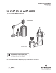
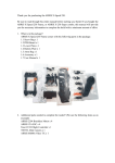
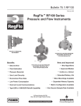
Figure 1. Panel Assembly
Figure 2. Enclosure Assembly
ER5K Kits
Table of Contents
DOPSM2095X012
September 2015
Contents
Section 1: Introduction . . . . . . . . . . . . . . . . . . . . . . . . . . . . . . . . . . . . . . . . . . . . . . . . . . . . . . . . . . . . 1
Section 2: Before You Begin. . . . . . . . . . . . . . . . . . . . . . . . . . . . . . . . . . . . . . . . . . . . . . . . . . . . . . . . 1
2.1 Safety, Installation and Operations Precautions. . . . . . . . . . . . . . . . . . . . . . . . . . .
2.1.1 TESCOM Electronic Controllers. . . . . . . . . . . . . . . . . . . . . . . . . . . . . . . . . .
2.1.2 Installation . . . . . . . . . . . . . . . . . . . . . . . . . . . . . . . . . . . . . . . . . . . . . . . . . . .
2.1.3 TESCOM Regulators. . . . . . . . . . . . . . . . . . . . . . . . . . . . . . . . . . . . . . . . . . . .
1
1
3
4
Section 3: Product Description . . . . . . . . . . . . . . . . . . . . . . . . . . . . . . . . . . . . . . . . . . . . . . . . . . . . 7
3.1
3.2
3.3
Kit Benefits. . . . . . . . . . . . . . . . . . . . . . . . . . . . . . . . . . . . . . . . . . . . . . . . . . . . . . . . . . .
3.1.1 Very high pressure stability. . . . . . . . . . . . . . . . . . . . . . . . . . . . . . . . . . . . .
3.1.2 Automation. . . . . . . . . . . . . . . . . . . . . . . . . . . . . . . . . . . . . . . . . . . . . . . . . . .
3.1.3 ERTune™ Program. . . . . . . . . . . . . . . . . . . . . . . . . . . . . . . . . . . . . . . . . . . . .
3.1.4 Items Included. . . . . . . . . . . . . . . . . . . . . . . . . . . . . . . . . . . . . . . . . . . . . . . .
Regulator Families. . . . . . . . . . . . . . . . . . . . . . . . . . . . . . . . . . . . . . . . . . . . . . . . . . . . .
Controlling System Pressure. . . . . . . . . . . . . . . . . . . . . . . . . . . . . . . . . . . . . . . . . . . .
7
7
7
7
7
7
8
Section 4: Technical Data . . . . . . . . . . . . . . . . . . . . . . . . . . . . . . . . . . . . . . . . . . . . . . . . . . . . . . . . . 10
Section 5: Installation. . . . . . . . . . . . . . . . . . . . . . . . . . . . . . . . . . . . . . . . . . . . . . . . . . . . . . . . . . . . . 11
5.1
5.2
5.3
Two Mounting Types . . . . . . . . . . . . . . . . . . . . . . . . . . . . . . . . . . . . . . . . . . . . . . . . . 11
System Leak Check. . . . . . . . . . . . . . . . . . . . . . . . . . . . . . . . . . . . . . . . . . . . . . . . . . . 14
ER5000 Tuning . . . . . . . . . . . . . . . . . . . . . . . . . . . . . . . . . . . . . . . . . . . . . . . . . . . . . . 14
Section 6: Wiring . . . . . . . . . . . . . . . . . . . . . . . . . . . . . . . . . . . . . . . . . . . . . . . . . . . . . . . . . . . . . . . . . . . 14
6.1
General Wiring. . . . . . . . . . . . . . . . . . . . . . . . . . . . . . . . . . . . . . . . . . . . . . . . . . . . . . . 14
Section 7: Maintenance. . . . . . . . . . . . . . . . . . . . . . . . . . . . . . . . . . . . . . . . . . . . . . . . . . . . . . . . . . . 16
Section 8: Drawings. . . . . . . . . . . . . . . . . . . . . . . . . . . . . . . . . . . . . . . . . . . . . . . . . . . . . . . . . . . . . . . 17
8.1
8.2
8.3
8.4
Table of Contents
Electrical Drawing. . . . . . . . . . . . . . . . . . . . . . . . . . . . . . . . . . . . . . . . . . . . . . . . . . . .
ER5K Kit Drawing . . . . . . . . . . . . . . . . . . . . . . . . . . . . . . . . . . . . . . . . . . . . . . . . . . . .
Regulator Drawings . . . . . . . . . . . . . . . . . . . . . . . . . . . . . . . . . . . . . . . . . . . . . . . . . .
8.3.1 Regulator Flow Booster. . . . . . . . . . . . . . . . . . . . . . . . . . . . . . . . . . . . . . . .
8.3.2 Pressure Reducing Regulator DK Series. . . . . . . . . . . . . . . . . . . . . . . . . .
8.3.3 Pressure Reducing Regulator 26-2000 Series. . . . . . . . . . . . . . . . . . . . .
8.3.4 Hydraulic Back Pressure Regulator 54-2100 Series. . . . . . . . . . . . . . . .
8.3.5 Back Pressure Regulator 26-1700 Series. . . . . . . . . . . . . . . . . . . . . . . . .
8.3.6 Control Air Regulator 44-5200 Series. . . . . . . . . . . . . . . . . . . . . . . . . . . .
Pressure Transducer. . . . . . . . . . . . . . . . . . . . . . . . . . . . . . . . . . . . . . . . . . . . . . . . . .
17
19
22
22
23
24
25
26
27
28
i
Section 1: Introduction
September 2015
ER5K Kits
DOPSM2095X012
Section 1: Introduction
This manual is valid only for ER5K kits ER5K-XXXX. The instructions for individual components
must also be read and followed and are either attached in the appendix or supplied separately.
Section 2: Before You Begin
WARNING
This device is not intended for or rated for use in hazardous locations.
1. Please contact your TESCOM representative for Explosion Proof options.
2. Avoid personal injury or property damage from sudden release of pressure or
bursting parts. Before proceeding with any installation procedures:
•Always wear protective clothing, gloves, and eyewear to prevent personal
injury, or property damage.
•Do not remove the ER5000 or any other component of the system while the
system is pressurized.
•Disconnect any operating lines providing air pressure, electric power, or a
control signal to the ER5000 prior to installation or maintenance.
•Use bypass valves or completely shut off the process to isolate the ER5000
and associated equipment from process pressure prior to installation or
maintenance. Relieve process pressure on both sides of the controller and
associated equipment.
•Use lock-out procedures to be sure that the above measures stay in effect
while you work on the equipment.
•Check with your process or safety engineer for any additional measures that
must be taken to protect against process media dangers.
Do not install, operate, or maintain an ER5000 controller, or any associated
equipment, without reading and fully understanding the installation guidelines
and operating instructions for every component of your application. To avoid
personal injury or property damage, it is important to carefully read, understand,
and follow all contents of this Getting Started guide, including all safety cautions
and warnings. If you have any questions about these instructions, contact your
TESCOM sales office before proceeding.
2.1 Safety, Installation and Operations Precautions
2.1.1
TESCOM Electronic Controllers
WARNING
Do not attempt to select, install, use, or maintain this controller, or accessory until you have
read and fully understood these instructions. Be sure this information reaches the operator
and stays with the product after installation. Do not permit untrained personnel to install,
use, or maintain this controller, or accessory. Improper selection, installation, maintenance,
misuse, or abuse of this controller, or related accessories can cause death, serious injury,
and/or property damage. Oxygen service requires special expertise and knowledge of
system design and material compatibility in order to minimize the potential for death,
serious injury, and/or property damage.
1
Section 1: Introduction
ER5K Kits
Section 2: Before You Begin
DOPSM2095X012
September 2015
Possible consequence include but are not limited to:
• High velocity fluid (gas or liquid) discharge
•
Electrocution
• Parts ejected at high speed
• Contact with fluids that may be hot, cold, toxic, or otherwise injurious
• Explosion or burning of the fluid
• Lines/hoses whipping dangerously
• Damage or destruction to other components or equipment in the system
CAUTION
1. Read and understand the user’s manual before operating the controller.
2. Inspect the controller, and accessories before each use.
3. Operate the unit only under specified environmental conditions.
4. Follow instructions in the manuals for proper wiring.
5. Never connect the controller, or accessories to a supply source having a voltage greater
than the maximum rated voltage of this controller, or accessory.
6. Never connect the controller, or accessories to a supply source having a pressure greater
than the maximum rated pressure of this controller, or accessory.
7. Never use anything but clean dry inert gases or air into the electropneumatic controller.
8. Start up sequence for electropneumatic controllers is:
a. Feedback loop must be installed and operational.
b. Electrical power should be applied and system setpoint reduced to its lowest
pressure output before turning on the pneumatic supply to the controller.
9. Refer to product label (modification specific) for maximum inlet pressures. If this
rated pressure cannot be found, contact your local Tescom representative for the
rated pressure prior to installation and use. Verify the designed pressure rating of all
equipment (e.g., supply lines, fittings, connections, filters, valves, gauges, etc.) in your
system. All must be capable of handling the supply and operating pressure.
10. Clearly establish flow direction of the fluid before installation of controllers, regulators,
valves, and accessories. It is the responsibility of the user to install the equipment in the
correct direction.
11. Remove pressure from the system before tightening fittings, gauges or components.
12. Never turn controller, regulator or valve body. Instead, hold the controller body and turn
fitting nut.
13. If a controller, regulator or valve leaks or malfunctions, take it out of service immediately.
14. Do not modify equipment or add attachments not approved by the manufacturer.
15. Apply pressure to the system gradually, avoiding a sudden surge of fluid or pressure
shock to the equipment in the system.
16. Regulators are not shut-off valves. Install a pressure relief device downstream of the
regulator to protect the process equipment from operating pressure increases. Shut off
the supply pressure when the regulator is not in use.
17. Periodic inspection and scheduled maintenance of your equipment is required for
continued safe operation.
18. The frequency of servicing is the responsibility of the user based on the application.
Never allow problems or lack of maintenance to go unreported.
Section 2: Before You Begin
2
Section 2: Before You Begin
September 2015
ER5K Kits
DOPSM2095X012
19. Read and follow precautions on compressed gas cylinder labels.
20. It is important that you analyze all aspects of your application and review all available
information concerning the product or system. Obtain, read, and understand the
Material Safety Data Sheet (MSDS) for each fluid used in your system.
21. Never use materials for controllers, regulators, valves, or accessories that are not
compatible with the fluids being used.
22. Users must test under normal operating conditions to determine suitability of materials
in an application.
23. Vent fluids to a safe environment, and in an area away from employees. Be sure
that venting and disposal methods are in accordance with Federal, State, and
Local requirements. Locate and construct vent lines to prevent condensation or
gas accumulation. Make sure the vent outlet is not obstructed by rain, snow, ice,
vegetation, insects, birds, etc. Do not interconnect vent lines; use separate lines if more
than one vent is needed.
24. Do not locate controllers, regulators, valves, or accessories using flammable fluids near
open flames or any other source of ignition. Use of Explosion Proof controllers may be
necessary to be in accordance with local electric codes.
25. Some fluids, when burning, do not exhibit a visible flame. Use extreme caution when
inspecting and/or servicing systems using flammable fluids to avoid death or serious
injury to employees. Provide a device to warn employees of these dangerous conditions.
26. Many gases can cause suffocation. Make certain the area is well ventilated. Provide a
device to warn employees of lack of Oxygen.
27. Never use oil or grease on these controllers, regulators, valves, or accessories. Oil and
grease are easily ignited and may combine violently with some fluids under pressure.
28. Have emergency equipment in the area if toxic or flammable fluids are used.
29. Upstream filters are recommended for use with all fluids.
30. Do not bleed system by loosening fittings.
31. Prevent icing of the equipment by removing excess moisture from the gas.
32. Always use proper thread lubricants and sealants on tapered pipe threads.
2.1.2Installation
Inspect the controller, and accessories for physical damage and contamination. Do not
connect the controller, or accessory if you detect oil, grease, or damaged parts. If the
controller, or accessory is damaged, contact your local TESCOM representative to have the
controller cleaned or repaired.
WARNING
Make sure that the components and materials used in the fluid handling system are
compatible with the fluid and have the proper pressure rating.
Make sure that the components used in the electronic system are compatible
with and have the proper voltage rating.
3
Section 2: Before You Begin
ER5K Kits
Section 2: Before You Begin
DOPSM2095X012
September 2015
REPAIR SERVICE
If a controller leaks or malfunctions, take it out of service immediately. You must have
instructions before doing any maintenance. Do not make any repairs you do not understand.
Have qualified personnel make repairs. Return any equipment in need of service to your
equipment supplier for evaluation and prompt service. Equipment is restored to the original
factory performance specifications, if repairable. There are flat fee repair charges for each
standard model. The original equipment warranty applies after a complete overhaul.
WARNING
Safe Component Selection
1. Consider the total system design when selecting a component to ensure safe,
trouble‑free performance.
2. The user is responsible for assuring all safety and warning requirements of the
application are met through his/her own analysis and testing.
3. Tescom may suggest material for use with specific media upon request.
Suggestions are based on technical compatibility resources through associations
and manufacturers. Tescom does NOT guarantee materials to be compatible with
specific media — THIS IS THE RESPONSIBILITY OF THE USER!
4. Component function, adequate ratings, proper installation, operation, and
maintenance are the responsibilities of the system user.
5. The user is responsible to be in accordance with all the necessary mechanical
and electrical codes required for installation and operation of the system. These
requirements include but are not limited to all explosion proof controllers.
6. The user is responsible for the selection of the proper model number of the
controller that would meet the application’s possible hazardous environment
or conditions.
WARNING
Do not modify equipment or add attachments not approved by the manufacturer.
2.1.3
TESCOM Regulators
WARNING
Do not attempt to select, install, use, or maintain this regulator, valve, or accessory
until you have read and fully understand these instructions.
Be sure this information reaches the operator and stays with the product after
installation. Do not permit untrained personnel to install, use, or maintain this
regulator, valve or accessory. Improper selection, improper installation, improper
maintenance, misuse, or abuse of regulators, valves or related accessories can cause
death, serious injury, and/or property damage. Oxygen service requires special
expertise and knowledge of system design and material compatibility in order to
minimize the potential for death, serious injury, and/or property damage.
Possible consequences include but are not limited to:
• High velocity fluid (gas or liquid) discharge
• Parts ejected at high speed
• Contact with fluids that may be hot, cold, toxic, or otherwise injurious
• Explosion or burning of the fluid
• Lines/hoses whipping dangerously
• Damage or destruction to other components or equipment in the system
Section 2: Before You Begin
4
Section 2: Before You Begin
September 2015
ER5K Kits
DOPSM2095X012
CAUTION
1. Inspect the regulator, valve, and accessories before each use.
2. Never connect regulators, valves, or accessories to a supply source having a pressure
greater than the maximum rated pressure of the regulator, valve, or accessory.
3. Refer to product label (model specific) for maximum inlet pressures. If this rated
pressure cannot be found, contact your local Tescom representative for the rated
pressure prior to installation and use. Verify the designed pressure rating of all
equipment (e.g., supply lines, fittings, connections, filters, valves, gauges, etc.) in your
system. All must be capable of handling the supply and operating pressure.
4. Clearly establish flow direction of the fluid before installation of regulators, valves,
and accessories. It is the responsibility of the user to install the equipment in the
correct direction.
5. Remove pressure from the system before tightening fittings, gauges or components.
6. Never turn regulator or valve body. Instead hold regulator or valve body and turn
fitting nut.
7. If a regulator or valve leaks or malfunctions, take it out of service immediately.
8. Do not modify equipment or add attachments not approved by the manufacturer.
9. Apply pressure to the system gradually, avoiding a sudden surge of fluid or pressure
shock to the equipment in the system.
10. Regulators are not shut-off devices. Install a pressure relief device downstream of the
regulator to protect the process equipment from overpressure conditions. Shut off the
supply pressure when the regulator is not in use.
11. Periodic inspection and scheduled maintenance of your equipment is required for
continued safe operation.
12. The frequency of servicing is the responsibility of the user based on the application.
13. Never allow problems or lack of maintenance to go unreported.
14. Read and follow precautions on compressed gas cylinder labels.
15. It is important that you analyze all aspects of your application and review all available
information concerning the product or system. Obtain, read, and understand the
Material Safety Data Sheet (MSDS) for each fluid used in your system.
16. Never use materials for regulators, valves, or accessories that are not compatible with
the fluids being used.
17. Users must test components for material compatibility with the system operating
conditions prior to use in the system.
18. Vent fluids to a safe environment, and in an area away from employees. Be sure
that venting and disposal methods are in accordance with Federal, State, and Local
requirements. Locate and construct vent lines to prevent condensation or gas
accumulation. Make sure the vent outlet is not obstructed by rain, snow, ice, vegetation,
insects, birds, etc. Do not interconnect vent lines; use separate lines if more than one
vent is needed.
19. Do not locate regulators, valves, or accessories controlling flammable fluids near open
flames or any other source of ignition.
20. Some fluids when burning do not exhibit a visible flame. Use extreme caution when
inspecting and/or servicing systems using flammable fluids to avoid death or serious
injury to employees. Provide a device to warn employees of these dangerous conditions.
5
Section 2: Before You Begin
ER5K Kits
Section 2: Before You Begin
DOPSM2095X012
September 2015
21. Many gases can cause suffocation. Make certain the area is well ventilated. Provide a
device to warn employees of lack of Oxygen.
22. Never use oil or grease on these regulators, valves, or accessories. Oil and grease are
easily ignited and may combine violently with some fluids under pressure.
23. Have emergency equipment in the area if toxic or flammable fluids are used.
24. Upstream filters are recommended for use with all fluids.
25. Do not bleed system by loosening fittings.
26. Prevent icing of the equipment by removing excess moisture from the gas.
27. Always use proper thread lubricants and sealants on tapered pipe threads.
CAUTION
Do not open packaging until ready for installation or in a clean environment. Product is
cleaned in accordance with CGA 4.1 and ASTM G93, Verification Type 1, Test 1 and Test 2.
With periodic verification of cleaning process to MIL-STD-1330D.
WARNING
Make sure that the components and materials used in the fluid handling system are
compatible with the fluid and have the proper pressure rating. Failure to do so can
result in death, serious injury, and/or property damage.
Inspect the regulator, valve, and accessories for physical damage and contamination.
Do not connect the regulator, valve, or accessory if you detect oil, grease, or damaged
parts. If the regulator, valve, or accessory is damaged, contact your local Tescom
representative to have the regulator cleaned or repaired.
REPAIR SERVICE
If a regulator or valve leaks or malfunctions, take it out of service immediately. You must have
instructions before doing any maintenance. Do not make any repairs you do not understand.
Have qualified personnel make repairs. Return any equipment in need of service to your
equipment supplier for evaluation and prompt service. Equipment is restored to the original
factory performance specifications, if repairable. There are flat fee repair charges for each
standard model. The original equipment warranty applies after a complete overhaul.
CAUTION
Proper Component Selection
1. Consider the total system design when selecting a component for use in a system.
2. The user is responsible for assuring all safety and warning requirements of the
application are met through his/her own analysis and testing.
3. Tescom may suggest material for use with specific media upon request. Suggestions are
based on technical compatibility resources through associations and manufacturers.
TESCOM does NOT guarantee materials to be compatible with specific media -- THIS IS
THE RESPONSIBILITY OF THE USER!
4. Component function, adequate ratings, proper installation, operation, and
maintenance are the responsibilities of the system user.
WARNING
Do not modify equipment or add attachments not approved by the manufacturer.
Failure to do so can result in death, serious injury and/or property damage.
Section 2: Before You Begin
6
Section 3: Product Description
September 2015
ER5K Kits
DOPSM2095X012
Section 3: Product Description
The ER5K Kits are designed to provide a complete pressure control system for the most
common pressure reducing and back pressure control applications. All the components
are completely assembled, professionally plumbed together and tested for proper
operation to save the user time and the inconvenience of not having all the accessories
and interconnections needed to get the system up and running. Kits are available with the
components mounted on a SST plate or mounted inside an enclosure.
The ER5000 is a unique and flexible electropneumatic, closed loop, PID controller. When
combined with a mechanical regulator and pressure transmitter in these kits, the system
provides precise control of pressures up to 10,000 psig / 690 bar. The included ERTune
software program provides an easy means of setup, tuning and data acquisition.
3.1
Kit Benefits
3.1.1
Very high pressure stability
——Pressure is independent of the flow (eliminates droop)
——Pressure is independent of the input pressure (eliminates decaying inlet effect)
3.1.2Automation
——Pressure can be controlled by a signal from a PC or PLC
——Easy integration into automated test cycles
3.1.3
ERTune™ Program
3.1.4
Items Included
3.2
Regulator Families
——Included with every ER5000, provides data acquisition routine
——Setup Wizard loads PID parameters for your regulator series
All ER5K kits includes:
——ER5000FI-1 w/ERtune program and Complete User Manual
——Mechanical Regulator (see “Regulator Families” below)
——4-20 mAmp Feedback Transducer; 0.125% accuracy
——ER Supply Regulator with relief valve and gauge
——Prewired Electrical Junction Box
——All connections and fittings
With ER5K kits, the customer has a choice of the most versatile mechanical regulators to
cover a wide range of applications, both pressure reducing and back pressure.
Table 1. Pressure Reducing Regulators
26-2000
High pressure regulator to control various output ranges up to 10,000 psig / 690 bar, segregated captured vent.
DK
Highly accurate and sensitive regulator with captured vent for low pressure (90 psig / 6 bar) or mid range
applications (600 psig / 40 bar) requiring significant flow capabilities.
44-5200
Piston sensed, venting regulator for mid-pressure range, low flow applications (600 psig / 40 bar).
Flow booster
Low pressure (90 psig / 6 bar), high flow diaphragm regulator for air or nitrogen service. Zinc body.
Table 2. Back Pressure Regulators
7
26-1700
High pressure regulator to control various back-pressure ranges up to 10,000 psig / 690 bar.
54-2100
High pressure regulator to control various back-pressure ranges up to 10,000 psig / 690 bar. Specially designed for
hydraulic applications (metal seat).
Section 3: Product Description
ER5K Kits
Section 3: Product Description
DOPSM2095X012
September 2015
USB
Connection
ER5000 Supply
Pressure
110 psig / 7.5 bar
PC
Adaptor
Regulator
Inlet Pressure
External
Transducer
Outlet Pressure
To Process
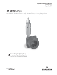
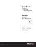
Figure 3. Typical Pressure Reducing Application
3.3
Controlling System Pressure
In a typical application, the Outlet Port of the ER5000 connects to the top of a Dome Loaded
or Air Actuated pressure reducing Regulator, usually through the included 1/2” SAE x
1/8” NPTF adaptor. This is shown in Figure 4. Supply Pressure of up to 120 psig / 8.2 bar, with
110 psig / 7.5 bar being typical, is provided to the ER5000 by an external source.
The ER5000 increases Pilot Pressure to the air actuator of the regulator by opening the
Pulse Width Modulation (PWM) solenoid valve at the Inlet Port and reduces pilot pressure
by opening the PWM solenoid valve at the Exhaust Port. Normally, the exhaust vents
to atmosphere. The controller, configured in External Feedback mode, senses System
Pressure through input from a transducer mounted downstream in the Process Line. Every
25 milliseconds, the controller reads the feedback and compares it to the setpoint, which it
receives from an external source or from a Profile in its onboard memory.
Section 3: Product Description
8
Section 3: Product Description
ER5K Kits
September 2015
DOPSM2095X012
USB Connection
ER5000
Inlet Port
Supply
Pressure
110 psig /
7.5 bar
Air Actuator
Pilot
Pressure To
Air Actuator
Vent Valve
Regulator
Inlet
Pressure
Exhaust
Valve
Inlet
Valve
ER5000
Exhaust Port
Pressure Vents
to Atmosphere
ER5000 Outlet Port
and Adaptor
Pilot
Pressure From
Air Actuator
Main Valve
PC
Setpoint
Source can be either a
digital signal provided over
USB or RS485, an analog
signal or a Profile stored in
onboard memory.
Feedback
For optimal system
performance, an accuracy
of 0.1% or better is required.
A less accurate transducer
can be used, but doing so
will degrade the accuracy of
the overall system.
Regulator
Inlet
Pressure
Captured Vent exhausts excess pressure
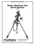
Figure 3. Typical Pressure Reducing Application (continued)
If feedback is lower than setpoint, the ER5000 activates the inlet valve, allowing Pilot Pressure
to flow into the actuator of the regulator. This causes the main valve of the regulator to open
up, resulting in an increase in downstream System Pressure. The ER5000 will continue to send
pilot pressure into the air actuator of the regulator until feedback and setpoint are equal. At
that point, the inlet valve closes, stabilizing the system at that pressure.
If feedback is higher than setpoint, the ER5000 activates the exhaust valve, releasing pilot
pressure from the regulator. The decrease in pilot pressure causes the main valve of the
regulator to close up and also causes the regulator vent to open, exhausting excess system
pressure (if your application uses a non-venting regulator, refer to page 36). The result is a
decrease in downstream system pressure. The ER5000 will continue to exhaust pilot pressure
until the feedback signal is equal to the setpoint. At that point, the exhaust valve closes,
stabilizing the system at that pressure. The air actuator, also known as the Ratio Actuator,
amplifies the force generated by the ER5000, allowing the pilot pressure to modulate system
pressure that may be many times greater, up to 30,000 psig / 2068 bar.
9
Section 3: Product Description
ER5K Kits
Section 4: Technical Data
DOPSM2095X012
September 2015
Section 4: Technical Data
Table 3. ER5K Pressure Reducing and Back Pressure Regulators Technical Data
Dash
Code
Regulator
Series
Transducer
pressure
range
psig / bar
Max. Regulator
Input Pressure
psi / bar
Flow
Coefficient
CV
Body
Material
Temperature
Venting
Weight
approx.
lbs / kg
CV: 1.5
Zinc
40 to 120°F
4 to 48°C
Yes*
1.6 / 0.75
CV: 2.2
Zinc
40 to 120°F
4 to 48°C
Yes*
1.6 / 0.75
CV: 0.35
SST
-15 to 165°F
-20 to 73°C
Yes
Captured
3.9 / 1.8
CV: 0.35
SST
-4 to 163°F
-26 to 74°C
Yes
Captured
6.2 / 2.8
CV: 0.06
SST
-15 to 165°F
-26 to 74°C
Yes
Captured
7.7 / 3.5
CV: 0.06
SST
-15 to 165°F
-26 to 74°C
Yes
Captured
7.7 / 3.5
CV: 0.06
SST
-15 to 165°F
-26 to 74°C
Yes
Captured
7.7 / 3.5
CV: 0.06
SST
-15 to 165°F
-26 to 74°C
Yes
Captured
7.7 / 3.5
ER5K-X Pressure Reducing Regulators
A
Flow
Booster
0 - 100
0-6
B
Flow
Booster
0 - 100
0-6
C
DK,
dome loaded
0 - 100
0-6
D
DK,
air loaded
0 - 600
0 - 40
F
26-2000
0 - 1500
0 - 100
G
26-2000
0 - 3000
0 - 160
H
26-2000
0 - 6000
0 - 400
J
26-2000
0 - 10,000
0 - 690
300 / 20.7
1000 / 69
SST:
10,000 / 690
ER5K-X Back Pressure Regulators
K
26-2100
1500
100
CV: 0.08
SST
-15 to 165 °F
-26 to 74°C
NA
7 / 3.2
L
26-2100
3000
160
CV: 0.08
SST
-15 to 165°F
-26 to 74°C
NA
7 / 3.2
M
26-2100
6000
400
CV: 0.08
SST
-15 to 165 °F
-26 to 74°C
NA
7 / 3.2
N
26-2100
10,000
600
CV: 0.08
SST
-15 to 165°F
-26 to 74°C
NA
7 / 3.2
P
26-1700
1500
100
CV: 0.14
SST
-40 to 165°F
-40 to 74°C
NA
7 / 3.2
R
26-1700
3000
160
CV: 0.10
SST
-40 to 165°F
-40 to 74°C
NA
7 / 3.2
S
26-1700
6000
400
CV: 0.10
SST
-40 to 165°F
-40 to 74°C
NA
7 / 3.2
T
26-1700
10,000
690
CV: 0.10
SST
-40 to 165°F
-40 to 74°C
NA
7 / 3.2
10,000 / 690
Operating Parameters
Electrical
Power Requirrement
90-264 VAC
Supply Requirement
Maximum Inlet Pressures
ER5000 Maximum Supply Pressure:
120 psig / 8.3 bar
ER Supply Regulator:
3500 psig / 241 bar
Section 4: Technical Data
Process Pressure
See specifications for Kit Regulator Type
Input Signals
Setpoint
USB, RS485, 4-20 mA, 1.5 VDC (0-10 VDC for
ER5XX0XV-1), downloaded Profile
Feedback (external)
4-20 mA or 1-5 VDC (0-10 VDC for ER5XX0XV-1)
Communication Protocol
USB and RS485
10
Section 5: Installation
ER5K Kits
September 2015
DOPSM2095X012
Section 5: Installation
WARNING
Do not attempt to select, install, use or maintain this regulator, valve or accessory
until you have read and fully understand these instructions.
Be sure this information reaches the operator and stays with the product after
installation. Do not permit untrained personnel to install, use or maintain this
regulator, valve or accessory.
5.1
Two Mounting Types
Kits are supplied with one of two mounting configurations
1 . Panel Version – Open Wall Mount
Figure 4. Open Wall Mount Panel
2 . Enclosure Version – Enclosed Wall Mount
Figure 5. Enclosed Wall Mount Panel
11
Section 5: Installation
ER5K Kits
Section 5: Installation
DOPSM2095X012
September 2015
Kits are mounted using 4 bolting locations in each corner
MOUNTING SURFACE
BOLT LOCATIONS
BOLT LOCATIONS
Note: Mounting hardware not included.
7.112 mm
0.28 in.
4x MOUNTING
LOCATIONS
4x MOUNTING
LOCATIONS
14.224 mm
0.56 in.
Note: maximum diameter available for mounting fasteners.
8.7 mm
0.3425 in.
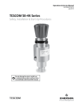
Figure 6. Wall Mount Installation
Section 5: Installation
12
Section 5: Installation
ER5K Kits
September 2015
DOPSM2095X012
Attach up to 3500 psig / 241 bar clean, dry inert gas to the ER Supply Regulator Inlet port .
Pressure supplied by the ER Supply Regulator to the ER5000 Inlet Port should not exceed
120 psig / 8 .3 bar . Attach Process supply pressure to the Process Inlet port . See specifications
for your Kit Regulator Type .
Attach Kit outlet to downstream process piping .
If desired, attach piping to Kit vent port .
*Note: Piping not included beyond what is already present in the kit
ER SUPPLY
REGULATOR
INLET
PROCESS INLET
OUTLET
VENT
Figure 7. ER5K Piping Installation
Connect power to terminals 1, 2 and 3 (See Section 6 . Wiring for details)
*Note: Power cord is customer supplied .
Plug USB Cable into device which has ERTune™ software installed (software supplied kit)
Figure 8. ERTune™ Software Installation
13
Section 5: Installation
ER5K Kits
Section 6: Wiring
DOPSM2095X012
5.2
September 2015
System Leak Check
After installation of all components and wiring:
•
•
•
5.3
Switch on the ER5000’s power supply .
Slowly apply ER supply pressure and then process pressure . Set the output pressure to
a safe value .
Check all fittings for tightness using leak test fluid. No bubbles should be seen.
ER5000 Tuning
•
In many applications, the standard factory settings will work satisfactorily, but to get
the best performance, “tuning” of the control loop parameters may be required . When
tuning, use conditions similar to the final application (i.e. similar pressures, flow and
medium) . A tuning procedure is provided in the ER5000 User Manual . There is also
“Help” available in the ERTune program itself, available on the “Diagnostic Tools” tab in
the ERTune program by clicking the “Tuning Tips” button .
Section 6: Wiring
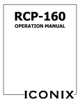
6.1
General Wiring
114C
114
100C
114A
101A
9
7
Power
Supply
17
19
21
23
TOP ROW
5
6
DC OK
3
1
15
DC
Fuse
DC LO
2
13
100B
+ –
AC
Input
Fuse
11
8
10
12
14
16
18
20
22
24
8
10
12
14
16
18
20
22
24
= prewired terminal connection
= open terminal connection
4
DSP
117
113A
10-24
114C
123
121A
117A
115
120A
123A
ER5000
BOTTOM ROW
5
100C
6
7
9
11
13
15
17
19
21
23
L N
J4 Terminal Pins
(“F” models only)
8 7 6 5 4 3 2 1
100A
101A
101A
100C
114B
113
118A
118
122A
120
116
J3 Terminal Pins
(all models)
12 11 10 9 8 7 6 5 4 3 2 1
121
122
TRANSDUCER
Figure 9. General Wiring
Section 6: Wiring
14
Section 6: Wiring
ER5K Kits
September 2015
6.2
DOPSM2095X012
Junction Box Wiring
Table 4. Prewired Power Connections
Junction Box Terminal
Wire
ER5000/Transducer Function
3
114A - braided (transducer)
power ground from transducer
5
100C - red (transducer)
+24V DC power to transducer
5
100C - violet
+24V DC power to ER5000
6
101A - gray
24V return (power ground) from ER5000
Table 5. Prewired Feedback Connections
Junction Box Terminal
Wire
ER5000/Transducer Function
9
114 - black (transducer)
+feedback input from transducer
9
114B - orange
+feedback input to ER5000
10
114C - yellow
-feedback input from ER5000
(jumpered to 15)
15
116 - tan
-feedback input from ER5000
(jumpered to 15)
Table 6. Power Connections - Required for Operation
Junction Box Terminal
Wire from 120V Source
1
line feed
2
neutral feed
3
ground
Table 7. Connections to Access Additional Functions
Junction Box Terminal
15
Wire
ER5000 Function
7
113 - brown
+setpoint input
8
113A - red
-setpoint input
11
118 - blue
+RS485 network connection
12
117
-RS485 network connection
13
118A - pink
analog signal output
14
115 - black
analog signal/board ground
16
117A - white
+5V output (5 mA max.)
17
120 - brown/white
+aux input #1
18
120A - red/black
-aux input #1
19
121 - orange/black
+aux input #2
20
121A - yellow/black
-aux input #2
21
122A - green/white
suspend control
22
123A - black/white
digital output/board ground
23
122 - blue/white
digital output #1
24
123 - gray/black
digital output #2
Section 6: Wiring
ER5K Kits
DOPSM2095X012
Section 7: Maintenance
September 2015
Section 7: Maintenance
The maintenance and repair of pressure equipment must only be performed by
trained personnel.
Since every application exists under different conditions, the user is responsible for
establishing a maintenance program based on their unique situation. Until enough data
is collected to set up a schedule, we recommend a 6 to 12 month check of the following,
however more frequent inspection and/or maintenance may be necessary.
1. Visual check for damages, especial of the tubing, electrical components and cables
2. Functional check
3. Check for leaks
A periodic calibration of the feedback pressure transducer depends on the user’s
requirements. Tescom recommends a yearly calibration.
Section 7: Maintenance
16
Section 8: Drawings
ER5K Kits
September 2015
DOPSM2095X012
Section 8: Drawings
The drawings in this manual are for reference only. For most up to date drawings please
contact your local TESCOM representative.
8.1
Electrical Drawing
Figure 10. Electrical Drawing
17
Section 8: Drawings
ER5K Kits
Section 8: Drawings
DOPSM2095X012
September 2015
Figure 10. Electrical Drawing (continued)
Section 8: Drawings
18
Section 8: Drawings
ER5K Kits
September 2015
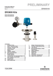
8.2
DOPSM2095X012
ER5K Kit Drawing
ER5K - E F T A
Table 8d.
DASH
NO.
Table 8a.
DASH
NO.
KIT CATEGORY
L
Parts Assembled on Plate
E
Parts in Assemled Enclosure
PORTING/FITTING SIZE
FOR INLET AND OUTLET, TUBING SIZE
A
Metric System
B
Imperial System
Table 8c.
DASH
NO.
O-RING MATERIAL
D
Buna (NBR)
T
Viton® (FKM)
U
Urethane (PUR)
Z
EP (EPDM)
Table 8b.
MAX CONTROL PRESSURE
BY TRANSDUCER
DASH
NO.
REGULATOR
TYPE
MATERIAL
bar
psi
A
Flow Booster
Pressure Reducing
Zinc
6
B
Flow Booster
Pressure Reducing
Zinc
C
DK Dome Load
Pressure Reducing
D
DK Air Load
Pressure Reducing
PORTING/FITING SIZE
SEAT
CV
100
Buna
1.5
12
1/2
6
100
Buna
2.2
12
1/2
SST
6
100
PCTFE
0.35
12
1/2
SST
40
600
PCTFE
0.35
12
1/2
Metric
Imperial
F
26-20 Air Load
Pressure Reducing
SST
100
1500
Vespel
0.06
6
1/4
G
26-20 Air Load
Pressure Reducing
SST
160
3000
Vespel
0.06
6
1/4
H
26-20 Air Load
Pressure Reducing
SST
400
6000
Vespel
0.06
6
1/4
J
26-20 Air Load
Pressure Reducing
SST
690
10000
Vespel
0.06
6
1/4
K
54-21 Air Load
Back Pressure
SST
100
1500
17-4 SST
0.08
6
1/4
L
54-21 Air Load
Back Pressure
SST
160
3000
17-4 SST
0.08
6
1/4
M
54-21 Air Load
Back Pressure
SST
400
6000
17-4 SST
0.08
6
1/4
N
54-21 Air Load
Back Pressure
SST
690
10000
17-4 SST
0.08
6
1/4
P
26-17 Air Load
Back Pressure
SST
100
1500
Teflon® (PTFE)
0.14
6
1/4
R
26-17 Air Load
Back Pressure
SST
160
3000
PCTFE
0.1
6
1/4
S
26-17 Air Load
Back Pressure
SST
400
6000
PCTFE
0.1
6
1/4
T
26-17 Air Load
Back Pressure
SST
690
10000
PCTFE
0.1
6
1/4
Notes:
1. Outlet transducer 0.1% accuracy.
2. Junction Box Supply Voltage: AC (100-250V).
3. Junction Box Communication: USB and RS-485.
4. Regulator for ER Supply: 44-5212-241V-003
5. Pressure can be transformed according to the equition: 1 MPa = 10 bar = 145 psig
19
Section 8: Drawings
ER5K Kits
Section 8: Drawings
DOPSM2095X012
September 2015
All dimensions are reference & nominal
Metric [millimeter] equivalents are in brackets
ER5000FI-1
JUNCTION BOX
PANEL
WIRING
GAUGE
REGULATOR
FOR ER SUPPLY
(44-5212-241V-003)
RELIEF VALVE
14.0"
[355.6]
REGULATOR
(Pressure Reducing
or Back Pressure)
26-2000 Series shown
TRANSDUCER
23.2"
[589.3]
7.57"
[192.5]
BOTTOM VIEW
Figure 11. ER5K Series Kit Assembled on Plate
Section 8: Drawings
20
Section 8: Drawings
ER5K Kits
September 2015
DOPSM2095X012
All dimensions are reference & nominal
Metric [millimeter] equivalents are in brackets
ER5000FI-1
ENCLOSURE
GAUGE
WIRING
JUNCTION BOX
REGULATOR
FOR ER SUPPLY
(44-5212-241V-003)
RELIEF VALVE
15 .8"
[401 .5]
REGULATOR
(Pressure Reducing
or Back Pressure)
DK shown
TRANSDUCER
25 .92"
[658 .4]
8 .04"
[204 .4]
BOTTOM VIEW
Figure 11. ER5K Series Kit Assembled on Plate (continued)
Junction Box
The Junction box is internally wired and
includes an AC/DC power converter,
fuses and wire terminal blocks mounted
on a DIN rail .
Power Unit (90 to 264 VAC)
Footprint: 7 .9 x 7 .9” [200 x 200]
Height: 4 .7” [120]
Analog Setpoint
(Customer Supplied)
PTransducer
ER5000FI-1
Digital Communication (RS485)
Figure 12. Junction Box
21
Section 8: Drawings
ER5K Kits
Section 8: Drawings
DOPSM2095X012
September 2015
8.3
Regulator Drawings
8.3.1
Regulator Flow Booster
Table 9. Pilot-Operated Diaphragm Style Regulator Dimensions
PART
NUMBER
INSTALLATION DIMENSIONS
269-529-04
INLET AND
OUTLET
PORT SIZE
OUTLET
GAUGE
PORT SIZE
PILOT
PORT SIZE
WEIGHT,
LBS
1/4 NPT
CV
1.5
Ø 3.0
3.4
1/4 NPT
1/8 NPT
1.6
1.4
269-529-06
3/8 NPT
2.2
2.8
Pilot Operated Diaphragm Style Regulator
Max. Inlet Pressure: 300 psig / 20.4 bar
Max. Outlet Pressure: 290 psig / 19.7 bar (100 psig / 6.9 bar when used with ER5000)
Temperature Range: 40 to 120°F / 4.4 to 48.9°C
Cast Zinc Body
Constant bleed from pilot pressure to vent for improved control
PILOT PORT
VENT PORT
INLET PORT
OUTLET PORT
GAUGE PORT
Figure 13. Pilot-Operated Diaphragm Style Regulator
Section 8: Drawings
22
Section 8: Drawings
ER5K Kits
September 2015
8.3.2
DOPSM2095X012
Pressure Reducing Regulator DK Series
Figure 14. DK Series Regulator
23
Section 8: Drawings
ER5K Kits
Section 8: Drawings
DOPSM2095X012
8.3.3
September 2015
Pressure Reducing Regulator 26-2000 Series
Figure 15. 26-200 Series Regulator
Section 8: Drawings
24
Section 8: Drawings
ER5K Kits
September 2015
8.3.4
DOPSM2095X012
Hydraulic Back Pressure Regulator 54-2100 Series
Figure 16. 54-2100 Series Regulator
25
Section 8: Drawings
ER5K Kits
Section 8: Drawings
DOPSM2095X012
8.3.5
September 2015
Back Pressure Regulator 26-1700 Series
Figure 17. 26-1700 Series Regulator
Section 8: Drawings
26
Section 8: Drawings
ER5K Kits
September 2015
8.3.6
DOPSM2095X012
Control Air Regulator 44-5200 Series
Figure 18. 44-5200 Series Regulator
27
Section 8: Drawings
ER5K Kits
Section 8: Drawings
DOPSM2095X012
8.4
September 2015
Pressure Transducer
Table 10. Transducer Pressure Ranges
AVAILABLE PRESSURE RANGE
Section 8: Drawings
615
(psig)
D51656
(bar)
100
6
600
40
1500
100
3000
160
6000
400
10,000
690
Figure 19. Pressure Transducer
28
Section 8: Drawings
ER5K Kits
September 2015
8.4.1
DOPSM2095X012
Transducer 615 Series (Imperial Versions)
Figure 20. 615 Series Transducer
29
Section 8: Drawings
ER5K Kits
Section 8: Drawings
DOPSM2095X012
8.4.2
September 2015
Transducer D51656-NB-XXX (Metric Versions)
Table 11. D51656-NB-XXX Technical Data
Specifications
Pressure ranges
Model S-10
bar
6
Over pressure safety
bar
35
Burst pressure
bar
42
Pressure ranges(1)
bar
40
100
160
400
690
Over pressure safety
bar
80
200
320
800
1500
Burst pressure
bar
400
800
1000
1700
3000
(1)
Materials
Wetted parts
Model S-10
Stainless steel
Case
Stainless steel
Synthetic oil (Halocarbon oil for oxygen applications)
Internal transmission fluid(2)
Power supply U+
U+ in VDC
10 to 30 (14 to 30 with signal output 0 to 10 V)
Signal output and
4 to 20 mA, 2-wire
Ra ≤ (U+ - 10 V) / 0.02 A
maximum ohmic load Ra
0 to 20 mA, 3-wire
Ra ≤ (U+ - 3V) / 0.02 A
0 to 5 V, 3-wire
Ra > 5 k
0 to 10 V, 3-wire
Ra > 10 k
(other signal outputs on request)
Adjustability zero/span
%
± 5 using potentiometers inside the instrument
Response time (10 to 90%)
ms
≤ 1 (≤ 10 ms at medium temperatures below < -30°C for pressure ranges up to 25 bar or with flush
diaphragm)
Insulation voltage
VDC
500(3)
Accuracy
% of span
≤ 0.5 {0.25}(5)
Non-linearity
% of span
≤ 0.2
Non-repeatability
% of span
≤ 0.1
1-year stability
% of span
≤ 0.2
(4)
(BFSL) according to IEC 61298-2
(at reference conditions)
Permissible temperature of
Medium(6)
Ambience
-30 to 100°C (-4 to 125°C)
-22 to 212°F (-40 to 257°F)
-20 to 80°C
-4 to 176°F
Storage(6)
-40 to 100°C
-40 to 212°F
Rated temperature range
0 to 80°C
32 to 176°F
(6)
Temperature coefficients within
rated temperature range
Mean TC of zero
% of span
≤ 0.2 / 10 K (<0.4 for pressure range ≤ 0.25 bar)
Mean TC of range
% of span
≤ 0.2 / 10 K
CE-conformity
Pressure equipment directive
EMC directive
97/23/EC
2004/108/EEC, EN 61 326 Emission (Group 1, Class B) and Immunity (Industrial locations)
Shock resistance
g
1000 according to IEC 60068-2-27
(mechanical shock)
Vibration resistance
g
20 according to IEC 60068-2-6
(vibration under resonance)
1. Vacuum, gauge pressure, compound range, absolute pressure, other pressure ranges and units are available.
2. Not for Model S-10 with pressure ranges > 25 bar.
3. NEC Class 02 power supply (low voltage and low current maximum 100 VA even under fault conditions).
4. Including non-linearity, hysteresis, zero point and full scale error (corresponds to error of measurement per IEC 61298-2). Adjusted in vertical mounting with lower
pressure connection.
5. Accuracy { } for pressure ranges ≥ 0 .25 bar.
6. Also complies with EN 50178, Tab. 7, Operation (C) 4K4H, Storage (D) 1K4, Transport (E) 2K3.
Section 8: Drawings
30
Section 8: Drawings
ER5K Kits
September 2015
8.4.3
DOPSM2095X012
Transducer D51656-NB-XXX (Europe Only)
Dimensions
Connection NB
DIN 175301-803 A
L-connector
1/4 NPT
per “Nominal size for US standard
tapered pipe thread NPT”
1.89ʺ [48]
27
1.14ʺ [20]
0.85ʺ [21.5]
0.51ʺ [13]
1/4 NPT
1.28ʺ
[32.5]
1.79ʺ [45.5]
1.06ʺ [27]
27
0.79ʺ [20]
1.12ʺ [28.5]
0.12ʺ [3]
0.12ʺ [3]
Ø 0.24ʺ [6]
All dimensions are reference & nominal
Metric [millimeter] equivalents are in brackets
G1/2B
Electrical Connection
L-connector DIN 175301-803 A
1
3
2
2-wire
U+ = 1
U- = 2
3-wire
U+ = 1
U- = 2
S+ = 3
Cable screen
Wire gauge
up to max. 1.5 mm2
Diameter of cable
6 to 8 mm (ship approval: 10 to 14 mm)
Ingress protection per IEC 60 529
IP 65
Figure 21. D51656-NB-XXX Transducer
31
Section 8: Drawings
ER5K Kits
DOPSM2095X012
Notes
September 2015
For Your Own Notes:
Notes
32
Emerson Process Management
Regulator Technologies Inc.
TESCOM
AMERICAS
12616 Industrial Blvd.
Elk River, MN 55330 USA
T +1 800 447 1250
+1 763 241 3238
F +1 763 241 3224
[email protected]
www.tescom.com
ASIA PACIFIC
3/F, Building #2 No. 1277
Xin Jin Qiao Road Jinqiao E.P.Z.
Pudong Shanghai 201206 China
T +86 21 2892 9970
F +86 21 2892 9001
[email protected]
www.tescom.com
EUROPE
An der Trave 23-25
23923 Selmsdorf, Germany
T +49 (0) 3 88 23/31-287
F +49 (0) 3 88 23/31-140
[email protected]
www.tescom-europe.com
MIDDLE EAST & AFRICA
PO Box 17033 Jebel Ali Free Zone-South
(Zone 2)
Dubai, UAE
T +971 4 811 8443
F +971 4 886 5465
[email protected]
www.tescom.com
Brandon House
23-25 Brandon Street
Hamilton ML3 6DA
South Lanarkshire, UK
T +44 1698 424 254
F +44 1698 459 299
[email protected]
www.tescom.com
DOPSM2095X012 ©TESCOM Corporation, 2015; All Rights Reserved.
TESCOM is a business unit of Emerson Process Management Regulator
Technologies, Inc. Trademarks are property of divisions of Emerson
Process Management.
The contents of this publication are presented for information purposes
only, and while effort has been made to ensure their accuracy, they are not
to be construed as warranties or guarantees, express or implied, regarding
the products or services described herein or their use or applicability.
All sales are governed by our terms and conditions, which are available
on request. We reserve the right to modify or improve the designs or
specifications of our products at any time without notice.