1
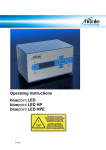
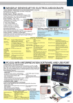
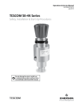
Handheld Pulse Oximeter OxyTrue®A
User Manual
Table of Contents
1. Intended Use – Warnings
3
2. Controls – Symbols – Display Modes
2.1 Controls and User Interfaces
2.2 Display Modes and Displayed Data
2.3 Symbols and Indicators
2.4 Audible Indicators
2.4.1 Pulse Tone (Beep)
2.4.2 Audible Warning Signal
2.4.3 Alarm Signals
4
4
5
6
7
7
7
7
3. Preparation for Use
7
4. Screen Contents – Menu Structure
4.1 Main Menu
4.1.1 Submenu: Alarm Settings
4.1.1.1 General Information
4.1.1.2 Adjusting Settings
4.1.2 Submenu: Data Management
4.1.2.1 General Information
4.1.2.2 Data
4.1.3 Submenu: Device Setup
4.1.3.1 General Information
4.1.3.2 Adjusting Settings
4.2. Other
4.2.1 Volume Control Shortcut
4.2.2 Brightness Control Shortcut
4.2.3 Power-Save Mode
7
7
7
7
8
8
8
8
9
9
9
10
10
10
10
5. Error Messages – Problems – Corrective Actions
5.1 General Information
5.2 Error Messages – Causes
5.3 Failure – Cause – Corrective Action
10
10
10
10
6. Maintenance – Cleaning
12
7. Symbol Definitions
12
8. Technical Specifications
12
9. Packing List – Accessories and Replacement Parts 13
10. OxyTrue®A PC-Software
13
11. Declaration of Conformity
14
Contact address
15
OxyTrue®A User Manual bluepoint MEDICAL GmbH & Co. KG 2007
3
1. Intended Use
The OxyTrue®A handheld pulse oximeter is indicated
for continuous or spot check monitoring of functional arterial oxygen saturation (SpO2) and pulse rate
of adult, pediatric and newborn patients in hospital,
hospital type facilities, transport, emergency care and
mobile environments as well as in the home care environment.
Warnings
Warnings are identified by the WARNING symbol shown above. Warnings alert the user to potential serious outcomes, such as death, injury, or
adverse events to the patient or user.
Do not make any clinical judgments based solely
on the OxyTrue®A. The monitor is intended only as
an adjunct in patient assessment. It must be used in
conjunction with clinical signs and symptoms. The
interpretation of the measurement values should be
done only by trained health care professionals.
Explosion hazard. Do not use OxyTrue®A in the
presence of flammable anesthetics mixture with air,
oxygen, or nitrous oxide.
Routinely monitor the patient to make sure the
OxyTrue®A is functioning and the sensor is correctly
placed.
Pulse oximetry measurements and pulse signals
can be affected by certain environmental conditions,
sensor application errors, and certain patient conditions. See the appropriate sections of this manual for
specific safety information.
If you are uncertain about the accuracy of any
measurement, check the patient’s vital signs by alternate means; then make sure the OxyTrue®A is functioning correctly.
The use of accessories, sensors, and cables other
than those specified may result in increased emission
and/or create invalid readings of the OxyTrue®A.
Failure to cover the sensor site with opaque material in high ambient light conditions may result in
inaccurate measurements.
OxyTrue®A User Manual bluepoint MEDICAL GmbH & Co. KG 2007
Do not silence the audible alarm function or decrease the audible alarm volume if patient safety could
be compromised.
The OxyTrue®A is a prescription device to be operated only by trained personnel. The monitor is for
attended monitoring only.
The OxyTrue®A is not defibrillator-proof. However, it may remain attached to the patient throughout
defibrillation or while an electrosurgical unit is in
use. The measurements may be inaccurate throughout
the defibrillation, or use of an electrosurgical unit,
and shortly thereafter. To avoid shock, the caregiver
should not hold the OxyTrue®A while using a defibrillator on a patient.
Disconnect the OxyTrue®A and sensor from the
patient throughout magnetic resonance imaging
(MRI) scanning. Induced current could potentially
cause burns.
Do not use a sensor or cables that appear damaged. Do not use sensors where optical components lie
open.
Ensure that the speaker is clear of any obstruction
and that the speaker holes are not covered. Failure to
do so could result in an inaudible alarm tone.
4
2. Controls – Symbols – Display Modes
2.1. Controls and User Interfaces
1
2
2
3
3
4
5
7
8
6
9
4
Side view
Front view
No.
Feature/Button
Function
1
Sensor Port
Port for the SpO2 sensor
2
USB
USB 2.0 interface
On/Off
To turn on the device: press and hold power
button briefly.
To turn off the device: press and hold power
button for approx. 3 seconds.
4
Arrow Buttons
(up/down)
Multifunction buttons used for
1. scrolling through menu items and
2. increasing/decreasing parameters.
3. From monitoring display modes: can be used
as shortcuts to volume/brightness control
5
Display Mode
Toggles between various display modes
6
Alarm On/Off
Silences alarm for max. 2 minutes or
reactivates silenced alarm.
7
Menu
Menu selection
8
ENTER button
Confirms selection
9
Pulse Tone
Turns pulse tone on/off
3
Symbol
OxyTrue®A User Manual bluepoint MEDICAL GmbH & Co. KG 2007
5
2.2. Display Modes and Displayed Data
Toggling Between Display Modes
The operator can toggle between various display modes by pressing the
button.
5
1
3
4
2
6
3
1
2
8
7
9
Display 1
1
2
Display 2
The SpO2 value shows the blood oxygen
saturation level expressed as a percentage.
The small numbers shown immediately above
and below the measured value on the right side
indicate the upper and lower alarm limits.
Pulse rate in beats per minute. The small numbers
immediately above and below the measured value
on the right side indicate the upper and lower
alarm limits.
3
Bar graph for pulse amplitude. Indicates the
dynamic pulse amplitude and rate. As the detected
pulse becomes stronger, more bars light with
each pulse. The reverse is true for weak pulses.
4
Pulse waveform (plethysmogram)
The reading is automatically adjusted to the pulse
strength; therefore, a waveform with strong
amplitude should be visible at all times.
OxyTrue®A User Manual bluepoint MEDICAL GmbH & Co. KG 2007
Display 3 to 5
Example of 15-minute trend
Display mode showing trend data for 15,
30 or 240-minute time interval parallel to
ongoing measurement
5
Time-interval trends
6
Trend waveform for SpO2 with continuous upper
and lower alarm limits in yellow
7
Trend waveform for pulse rate with continuous
upper and lower alarm limits in yellow
8
Pulse indicator
9
Start and end times
6
2.3. Symbols and Indicators
1
3
4
6
2
5
No.
Symbols/Indicators
Definition
1
Battery level indicator. The three segments represent
the battery charge level. The symbol flashes red when
the battery capacity is low.
2
Current time, displayed in 12h or 24h format
3
Alarm silenced indicator. The audible alarm can be
silenced for a maximum period of two minutes.
4
Pulse tone off
5
The colour of the bar graph is an indicator for signal
quality.
- Green: good signal quality, very accurate
measurement.
- Yellow: average signal quality, measurement may
be inaccurate.
- Red: poor signal quality, unreliable measurement.
6
Memory symbol
The device’s memory for measurement data is full.
No new data can be stored. Old data can be erased or
overwritten.
OxyTrue®A User Manual bluepoint MEDICAL GmbH & Co. KG 2007
7
2.4. Audible Indicators
2.4.1. Pulse Tone (Beep)
During monitoring a pulse beep is sounded for every
detected pulse. The pitch of the pulse tone is dependent on the measured SpO2 value. A higher pitch is
indicative of a higher oxygen saturation.
The pulse tone volume can be adjusted under the
menu item “Volume”.
The pulse tone can be also silenced using the button. Pressing the button a second time will reactivate
the pulse tone.
2.4.2. Audible Warning Signal
(Beep, Beep, … 5 Seconds …, Beep, Beep)
Error or warning messages; for example, the OxyTrue® A device will indicate that the sensor has slipped off the finger by sounding an audible warning
signal.
2.4.3 Alarm Signals
When an alarm is triggered the device will emit a
loud, high-pitched, pulsating tone in addition to the
visual alarm.
The alarm volume is not adjustable; however, it is
possible to silence the alarm for a period of two minutes using the button.
Once triggered, an alarm will only reset if the cause of
the alarm has been resolved.
Individual alarm limits can also be completely deactivated if necessary.
3. Preparation for Use
Battery Installation
• Slide down the cover of the battery compartment
on the rear panel of the device.
• Insert three batteries (1.5 volt, AA).
• Ensure correct orientation of batteries in
accordance with polarity markings.
• Slide battery-compartment cover closed.
Connecting the SpO2 Sensor
Plug the sensor cable into the sensor port located on
the top edge of the device. The markings on the plug
and port must match and face upward.
Turning on the Device
Press and hold button briefly until an opening
“splash screen” appears. After the power-on self-test
OxyTrue®A User Manual bluepoint MEDICAL GmbH & Co. KG 2007
is successfully completed the device is ready for
monitoring.
Beginning Monitoring
As soon as a sensor is connected and correctly positioned on the patient, monitoring begins automatically.
Turning Off Device
Press and hold button for several seconds. The
OxyTrue®A device will also power off automatically
after 5 minutes when not in use.
4. Screen Contents – Menu Structure
4.1 Main Menu
All important and frequently
used settings are accessible
through the main menu,
which can be opened by
pressing the
button.
Navigating the Menu
buttons to scroll through menu items.
Use the
The currently selected menu item is highlighted by a
button to confirm your
coloured frame. Press the
selection.
Entering Data
In some submenus it is possible to adjust a certain
parameter. In this case the parameter can be increased
or decreased using the
buttons. The value will increase or decrease more quickly when the respective
button to confirm
button is held down. Press the
the new value.
Exiting Menu and Returning to Display
Select the menu item “EXIT” to return immediately
to the monitoring display.
If no button has been pressed for more than 30 seconds the device will automatically return to the monitoring screen.
4.1.1 Submenu: Alarm Settings
4.1.1.1 General Information
With the OxyTrue®A device the alarm limits for SpO2
and pulse can be set individually. The current alarm
limits are shown as small numbers above and below
the measured values on the right side. If a measured
value either exceeds the upper limit or falls below the
8
lower limit, visual and audible alarms will be triggered immediately.
Visual alarm
When an alarm has been triggered the critical value
will flash red together with the violated alarm limit.
Figure: Visual alarm
which was triggered by
a violation of the lower
SpO2 alarm limit.
automatically stored in the devices memory, together
with the respective alarm limits, date and time. The
device warns the user when the memory is almost full
by displaying the
symbol. A maximum of 50 data
sets can be stored in the memory. After this maximum
has been reached the oldest data set is overwritten
upon confirmation by the user. Stored data sets can
be retrieved and erased under the menu item “Data
management”. The data sets can also be stored and
processed with the user-friendly OxyTrue®A PCSoftware.
4.1.2.2 Data
An alarm will also be triggered if the sensor slips off
the patient, if the signal quality remains poor over a
longer period of time or if a sensor is disconnected
from the device, provided that valid measurement
data have been recorded beforehand.
4.1.1.2 Adjusting Settings
Use Data Management menu to
• view remaining recording time in minutes
• access list of stored data sets
• delete all data in memory
Selection with
buttons
Selection/confirmation with
button
Alarm Settings menu
The upper and lower alarm limits for SpO2 and pulse
rate can be adjusted using this menu. “Off” deactivates the alarm limit.
Default limits
Limit changes are in effect only as long as the monitor
remains on. When it is turned off, the default limits
are stored. When the monitor is turned on, the default
limits will be in effect.
4.1.2 Submenu: Data Management
4.1.2.1 General Information
Recording Data
The OxyTrue®A device can store up to 48 hours of
monitoring data. Each individual data set, regardless
of its actual length, uses at least 15 minutes of memory space. A new data set is generated automatically
each time the device is turned on. When the device is
turned off, all of the measurements that were taken are
OxyTrue®A User Manual bluepoint MEDICAL GmbH & Co. KG 2007
Stored Data menu
List of all stored data sets. Retrieve selected data set
by pressing the
button.
Select “Back” to return to
the list of stored data or
“Delete” to erase the data
set shown.
The stored measurements are displayed in graphic
form together with the date, start time and duration of
the recording. The SpO2 reading is shown in green,
and the pulse reading in red. The yellow lines represent the respective alarm limits.
9
4.1.3 Submenu: Device Setup
4.1.3.1 General Information
First, select between 12h mode and 24h mode; then
set date and time. Settings for date and time are not
erased when the batteries are temporarily removed.
This submenu offers access to various device setbutton.
tings; confirm selection by pressing the
4.1.3.2 Adjusting Settings
Adjust display brightness using the
Confirm new setting by pressing the
buttons.
button.
Please note: Very high brightness settings will shorten battery life considerably!
Adjust the pulse tone volume using the
Confirm new setting by pressing the
buttons.
button.
Depending on the firmware, up to nine different language options are available here for selection. All
messages and menus will be displayed in the selected
language.
Stable: When this setting is selected any strong and
sudden variations in data will not immediately affect
the reading (data incorporated over time); minor irregularities have little or no effect on the displayed
reading.
Standard: Averaging parameters used for this setting
are between those of the stable and sensitive settings.
Sensitive: The reading is more sensitive to irregularities but reacts very quickly to any changes in measured parameters.
OxyTrue®A User Manual bluepoint MEDICAL GmbH & Co. KG 2007
Service
The Service submenu is protected by a PIN code;
only authorised service personnel can access this
menu.
10
4.2 Other
4.2.1 Volume Control Shortcut
If the button is pressed during any monitoring display mode the volume control screen will open.
buttons. Confirm new
Adjust volume using the
setting by pressing the
button.
4.2.2 Brightness Control Shortcut
If the button is pressed during any monitoring display mode the brightness control screen will open.
buttons. Confirm new
Adjust brightness using the
setting by pressing the
button.
4.2.3 Power-Save Mode
material in high ambient light conditions
• Venous pulsation
• Dysfunctional haemoglobin
• Low perfusion
5.2 Error Messages – Causes
“No sensor!”
The sensor is not connected properly to the device.
– Check sensor connection.
“Probe off!”
The sensor has been removed from the monitoring
site. – Check that the sensor is properly attached to
the patient.
“Low battery!”, battery symbol blinking red
The battery is almost completely discharged.
– Replace batteries immediately.
“Sensor fault!”
The connected sensor is either defective or not compatible with the device – check sensor.
Power-Safe Mode
The device’s display can be turned off to save power
and extend battery life. This can be accomplished by
pressing and holding the
button until Countdown
Display appears on the screen. The display can be turned on again by pressing any button. If an alarm is
triggered, the display will be turned on automatically.
5. Error Messages – Problems
– Corrective Actions
5.1. General Information
Physiological conditions, medical procedures, or external agents that may interfere with the monitor’s
ability to detect and display accurate measurements
include:
• Incorrect applications of the sensor
• Placement of the senor on an extremity with a
blood pressure cuff, arterial catheter, or
intravascular line
• Excessive patient activity
• Intravascular dyes
• Externally applied colouring agents, such as
nail polish
• Failure to cover the sensor site with opaque
OxyTrue®A User Manual bluepoint MEDICAL GmbH & Co. KG 2007
“Device defective!”
Fatal device error, e.g. resulting from improper handling, such as use with computed tomography. – The
device must be sent in to the Service Department.
“Too much ambient light!”
High ambient light sources near the sensor, e.g. surgical lights. – Shield sensor more effectively from external light.
“Bad signal quality”
Poor-quality pulse signal, for example as a result of
low perfusion. – Move the sensor to a different site
on the patient or provide more effective monitoring
conditions.
5.3 Failure – Cause – Corrective Action
Problem: There is no response to the Power button.
Cause – Corrective Action: Ensure that the Power
button is fully depressed. The batteries may be missing, discharged, or oriented incorrectly. Install new
batteries.
Problem: No pulse signal found
Cause – Corrective Action: Check the patient. Check
the sensor directions for use to determine if an appropriate sensor is being used and if it is applied properly.
11
Check sensor and extension cable connections. Test
the sensor on another subject. Try another sensor or
extension cable.
Perfusion may be too low for the monitor to track the
pulse. Check the patient. Test the monitor on yourself.
Change the sensor site. Try another sensor.
Interference due to patient activity may be preventing
the monitor from tracking the pulse.
Keep the patient still, if possible. Verify that the sensor
is securely applied and replace it if necessary. Change
the sensor site.
The sensor may be too tight, there may be interference
due to ambient light, or the sensor may be on an extremity with a blood pressure cuff, arterial catheter, or
intravascular line. Reposition sensor, as necessary.
Electromagnetic interference may be preventing the
monitor from tracking the pulse. Remove the source
of interference.
Problem: After a valid measurement the pulse signal can not be found anymore
Cause – Corrective Action: Check the patient. Check
the sensor directions for use to determine if an appropriate sensor is being used and if it is applied properly.
Check sensor and extension cable connections. Test
the sensor on another subject. Try another sensor or
extension cable.
Perfusion may be too low for the monitor to track the
pulse. Check the patient. Test the monitor on yourself.
Change the sensor site. Try another sensor.
Interference due to patient activity may be preventing
the monitor from tracking the pulse.
Keep the patient still, if possible. Verify that the sensor
is securely applied and replace it if necessary. Change
the sensor site.
The sensor may be too tight, there may be interference
due to ambient light, or the sensor may be on an extremity with a blood pressure cuff, arterial catheter, or
intravascular line. Reposition sensor, as necessary.
Electromagnetic interference may be preventing the
monitor from tracking the pulse. Remove the source
of interference.
OxyTrue®A User Manual bluepoint MEDICAL GmbH & Co. KG 2007
Problem: No pulse tone
Cause – Corrective Action: Continue to listen for the
pulse beep tone as the monitor is used. If it does not
sound with each pulse it indicates one of the following: Pulse beep volume is off. – Switch volume on.
Speaker/audio has malfunctioned. Signal is corrupted.
OxyTrue®A has stopped functioning. – Call Service
Department.
Other problems:
EMI (Electromagnetic Interference)
Caution: This device has been tested and found to
comply with the limits for medical devices according
to EN 60601-1-2, (second edition), and the Medical
Device Directive 93/42/EEC. These limits are designed to provide reasonable protection against harmful
interference in a typical medical installation.
Due to the proliferation of radio-frequency transmitting equipment and other sources of electrical noise
in healthcare environments, it is possible that high
levels of such interference due to close proximity, or
strength of a source, may result in disruption of performance of this device. Examples of noise sources in
healthcare environments that could cause electromagnetic interference are:
•
•
•
•
•
Electrosurgical units
Cellular phones
Mobile two-way radios
Electrical appliances
High-definition televisions (HDTV´s)
The monitor is designed for use in environments in
which the pulse can be obscured by electromagnetic
interference. During such interference, measurements
may seem inappropriate or the monitor may not seem
to operate correctly.
Disruption may be evidenced by erratic readings, cessation of operation, or other incorrect functioning. If
this occurs, the site of use should be surveyed to determine the source of disruption, and the following
actions taken to eliminate the source:
• Turn equipment in the vicinity off and on to
isolate the offending equipment.
• Reorient or relocate the interfering equipment.
• Increase the distance between the interfering
equipment and this equipment.
12
The monitor generates, uses, and radiates radio frequency energy. If it is not installed and used in accordance with these instructions, the monitor may
cause harmful interference with other devices in the
vicinity.
6. Maintenance – Cleaning
Maintenance and cleaning
There are no user-serviceable parts inside the OxyTrue®A The cover should only be removed by qualified service personnel.
The monitor requires no calibration. If service is necessary, contact qualified service personnel or your
local sales representative.
Caution
Do not spray, pour, or spill any liquid on the OxyTrue®A, its accessories, connectors, switches, or openings in the enclosure as this may damage the monitor.
Surface-clean
Use a soft cloth dampened with either a commercial,
nonabrasive cleaner, or a solution of 70% alcohol in
water. Lightly wipe the surface of the monitor.
Desinfection
Use a soft cloth saturated with a solution of 10% chlorine bleach in tap water.
7. Symbol Definitions
Attention!
See instructions for use!
Manufacturer
Date of manufacture
8. Technical Specifications
Measurement Range:
SpO2: 45 to 100%
Pulse Rate: 20 to 300 beats per minute (bpm)
Accuracy:
SpO2: +/- 2% (70 to 100%)
Pulse Rate: +/- 1 digit ( 100 bpm);
+/- 1% (> 100 bpm)
Display :
• OLED colour graphic display, 262,000 colours,
128 x 160 pixels
• Data displayed: oxygen saturation, pulse rate,
plethysmogram, bar graph, short-term and
long-term trends
• Indicators: signal quality, pulse amplitude,
battery status, alarm silenced, sensor detection,
sensor disconnection
Trend Information:
• Long-term Trends: up to 48 hours
• Short-term Trends: 15 min / 30 min / 4 hrs
Environmental Conditions:
• Operating conditions: 0 to 50°C; 15 to 95% RH;
600 to 1300 hPa
• Storage conditions: -20 to 70°C; 10 to 95% RH;
600 to 1500 hPa
Other:
• Class IIb Product
• Water-resistant construction
• Type BF
• Dimensions (lxwxh): 11.8 cm x 6 cm x 2.5 cm
• Weight: approx. 160 g (with batteries, without sensor)
• Power Supply: 3 batteries (1.5 volt, AA)
• Battery Life: > 2 days of continuous operation, or
approx. 5 days in power-save mode
Type BF
Order Number:
1020112001
S/N
Serial number
P/N
Product number
Applied Standards:
EN 60601-1, EN 865, ISO 9919:2005
Observe applicable waste disposal
regulations
European Union approval
OxyTrue®A User Manual bluepoint MEDICAL GmbH & Co. KG 2007
13
9. Packing List – Accessories and
Replacement Parts
Packing List:
• OxyTrue®A, main unit
• SC 6500 SoftCap® Sensor
• OxyTrue®A PC-Software
• USB data cable
• Silicone protector
• 3 AA batteries
Accessories and Replacement Parts:
• SoftCap® Sensor, SC 6500, P/N 1020132001
3rd generation SoftSensor, 1.2m cable length,
silicone cable
• SoftFlap® Finger Sensor, SF 6500, P/N 1020132002
finger-clip sensor, 1.2m cable length, PVC cable
• Extension Cable, XT 6500, P/N 1020122057
1.2m cable length, PVC cable
• Extension Cable, XT 6501, P/N 1020122058
2.4m cable length, PVC cable
• Universal Mounting Kit, P/N 1020122059
V-adapter with female pole-mount thread
• Universal Pole-Mount Adapter, P/N 1020122060
Adapter with vertical and horizontal adjustment
• Carrying Bag, P/N 1020122061, Carrying bag for
main unit and sensor, with shoulder strap
• OxyTrue®A Silicone Protective Cover,
P/N 1020122056
• USB Data Cable, P/N 1020122057
• CD-ROM OxyTrue®A PC-Software, P/N
1020410001
Additional sensors available upon request.
OxyTrue®A User Manual bluepoint MEDICAL GmbH & Co. KG 2007
10. OxyTrue®A PC-Software
With the user-friendly OxyTrue®A PC-Software all
saved data can be stored on a PC via the USB interface. This software offers a multitude of functions for
more advanced analysis and archiving of the measured data.
For more information please read the enclosed software manual.
14
11. Declaration of Conformity
OxyTrue®A User Manual bluepoint MEDICAL GmbH & Co. KG 2007
bluepoint MEDICAL GmbH & Co. KG
An der Trave 15
23923 Selmsdorf
Germany
Phone: +49 (38823) 548 8000
Fax: +49 (38823) 548 8029
E-mail: [email protected]
OxyTrue®A – User Manual, Version: EN 1.1
11/2007
www.bluepoint-medical.com