1
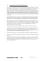
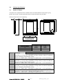
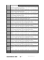
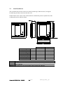
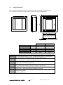
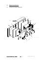
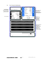
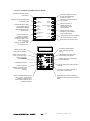
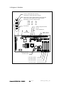
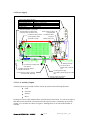
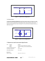
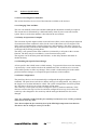
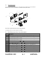
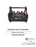
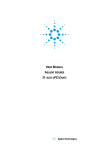
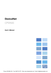
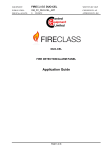
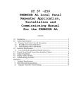
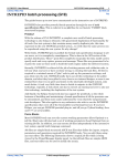
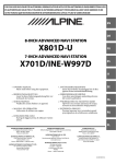
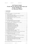
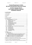
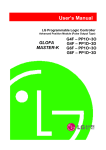
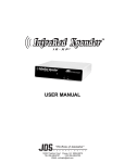
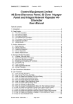
Discovery 1-4 Loop 96 Zone, 40-Character
Analogue Addressable Control Panel
Application Guide
Contents
Page
1.0
Introduction and Typical System Illustration
2
2.0
Cabinet Specifications
4
3.0
Hardware Specifications
7
4.0
Software Specifications
14
5.0
Panel Enhancements
18
6.0
Compatible Field Devices
20
Appendices
i
Other Relevant Documentation
Document Ref: DV40APP / Rev 2 09/02/2010 Page 1 of 23
23
Raised by GG Checked by JBJ ___ Approved by___JBJ
1.0
Introduction and Typical System Illustration
The 96 Zone, 40 Character Discovery analogue addressable panel is available as a 1-4 loop
panel using plug-in loop driver cards. Each loop is rated at 500mA and will control up to 126
Apollo, XP95 or Discovery devices. All addresses may be configured as cause/effect
outputs, with up to 255 different programmable groups and 3 independently programmable
output bits per address. Discovery mode changes are configured by the panel’s internal clock
and may differentiate between weekday and weekend functions. Loop inputs may also be
configured to change selected loop devices between modes where temporary mode changes
are required. Panels are housed in well-designed enclosures and are finished in hardwearing
epoxy paint.
The motherboard electronics are fixed to a detachable chassis thus facilitating a completely
empty enclosure for first fix installation. Top entry plastic grommets, bottom/rear entry
knockouts for mains, and rear entry knockouts are designed to assist with cable installation.
The panel has a 4 line x 20 character backlit LCD display, showing device address, zone,
type, status and location text. The LCD display provides capacity for 40 characters of user
programmable device text. It is also used as a menu-driven engineers’ configuration display.
User controls are accessed by means of keyswitch enabled membrane controls, with
password protection for engineer purposes.
96 zonal LEDs are provided as standard and “plug-in” printer is available as an option.
The panel provides 2 common fire changeover relays and 1 common fault changeover relay,
each rated at 1A, 30V DC. Four fully monitored panel inputs are provided for remote
silence, remote reset, remote evacuate and remote fault. The evacuate input will operate the
general alarms and may be programmed to operate the fire relay.
The panel may control up to 14 repeaters with full user capability via RS485 data comms.
Extensive panel and network cause/effect programming is achieved via the PC programming
package.
Full networking with other 96 Zone, 40 Character Discovery panels, network repeaters and
graphics package may be achieved with an additional plug-in network driver card. Network
cause/effect may be programmed between 96 Zone, 40 Character Discovery panels, and
active network repeaters.
Document Ref: DV40APP / Rev 2 09/02/2010
Page 2 of 23
Raised by GG Checked_ _JBJ
FIR
E
BRE
AK
PR
BAR
TOR
ONI
H MT
ITC RUP
SIWNTER
I
N
MI H
WIT
ISOLATOR
RE
OU
LAY
5
44
A1
FIR
E
BRE
AK
GLA
ES
S
SS
HERE
REM
OTE
TOR
ICA
IND
5
44
A1
A1
FIR
E
BRE
AK
GLA
ES
S
SS
5
44
A1
HERE
5
44
A1
S
OU
RD
ZA
HA
S
SS
HERE
EA
AR
R
RIE
RE
FI
&
T
UL
FA
MS
AR
AL YS
LA
RE
ER
AMPG
E DRIN
FIORNITO
M
G
IN
SH
UI
NG
TI M
EX STE
SY
FIR
BEA
AL
ON
TI
EN NEL
NV PA
CO RE
FI
L
NE
PA
SS
HERE
ER
AT
PE
RE
1
2
3
4
5
6
7
8
TH O
WI I/
K
L
NE OR
PA ETW
C N
MI
MI NEX ITY
KO CIL
FA
X
NE
KO
K
OR
TW
NE
R
GE
NA M
MA TE
M YS
AR S S
L
A IC
PC APH
GR
ISOLATOR
Document Ref: DV40APP / Rev 2 09/02/2010
X
NE
KO
K
OR
TW
NE
NG
MI
D AM
AN OGR
AD PR
O
L D
UP LOA
PC WN
DO
E
GLA
S
NE
ZONE
ZONE
ZONE
ZONE
ZONE
ZONE
ZONE
ZO
ER
AT
PE
RE
AK
ES
&
YS
LA
RE
R
CTO
ETE
MD
BRE
PR
RE
FI
T
UL
FA
Y
ER
OV EL
SC AN
DI 4 P
1-
4
44
A1
7
4/
44
PR
BAR
6
44
A1
NIT
TU
TPU
PR
LO
OL OR
AP LAT
S
AN
TR
R
RIE
GLA
ES
Page 3 of 23
Raised by GG Checked_ _JBJ
ER
AT
PE
RE
2.0
Cabinet Specifications
2.1
Surface Cabinets
All cabinets are manufactured from 18SWG sheet steel and finished in satin texture epoxy
powder stove paint. Top entry grommets and rear entry knockouts are provided.
Cabinet colour: RAL 7035 Light Grey
c
b
a
Protection Plugs
a
b
c
1-4 loop
13 off
480mm
410mm
144mm
Repeaters
13 off
370mm
325mm
106mm
Part No Description
2604010 96 Zone, 40 Character Discovery 1 loop analogue/addressable control panel with 96
zone LEDs, c/w 1 loop card, expandable to 4 loops with three 2500/130 Additional
loop card. English, printed display overlay.
Cabinet size - 480h x 410w x 144d. Space for printer and 2 x 12V 12Ah battery set.
2604011 96 Zone, 40 Character Discovery 2 loop analogue/addressable control panel with 96
zone LEDs, c/w 2 loop cards, expandable to 4 loops with two 2500/130 Additional
loop cards. English, printed display overlay.
Cabinet size - 480h x 410w x 144d. Space for printer and 2 x 12V 12Ah battery set.
2604012 96 Zone, 40 Character Discovery 3 loop analogue/addressable control panel with 96
zone LEDs, c/w 3 loop cards, expandable to 4 loops with one 2500/130 Additional
loop card. English, printed display overlay.
Cabinet size - 480h x 410w x 144d. Space for printer and 2 x 12V 12Ah battery set.
2604013 96 Zone, 40 Character Discovery 4 loop analogue/addressable control panel with 96
zone LEDs, c/w 4 loop cards. English, printed display overlay.
Cabinet size - 480h x 410w x 144d. Space for printer and 2 x 12V 12Ah battery set.
Document Ref: DV40APP / Rev 2 09/02/2010
Page 4 of 23
Raised by GG Checked_ _JBJ
Part No Description
2604014 96 Zone, 40 Character Discovery 5 loop analogue/addressable control panel with 96
zone LEDs, c/w 5 loop cards, expandable to 8 loops with three 2500/130 Additional
loop cards. English, printed display overlay.
Cabinet size - 480h x 670w x 144d. Space for printer and 2 x 12V 12Ah battery set.
2604015 96 Zone, 40 Character Discovery 6 loop analogue/addressable control panel with 96
zone LEDs, c/w 6 loop cards, expandable to 8 loops with two 2500/130 Additional
loop cards. English, printed display overlay.
Cabinet size - 480h x 670w x 144d. Space for printer and 2 x 12V 12Ah battery set.
2604016 96 Zone, 40 Character Discovery 7 loop analogue/addressable control panel with 96
zone LEDs, c/w 7 loop cards, expandable to 8 loops with one 2500/130 Additional
loop card. English, printed display overlay.
Cabinet size - 480h x 670w x 144d. Space for printer and 2 x 12V 12Ah battery set.
2604017 96 Zone, 40 Character Discovery 8 loop analogue/addressable control panel with 96
zone LEDs, c/w 8 loop card. English, printed display overlay.
Cabinet size - 480h x 670w x 144d. Space for printer and 2 x 12V 12Ah battery set.
2604018 96 Zone, 40 Character Discovery 1 loop analogue/addressable control panel with 96
zone LEDs, c/w 1 loop card, expandable to 4 loops with three 2500/130 Additional
loop card. Insertable type display overlay with English printed inserts.
Cabinet size - 480h x 410w x 144d. Space for printer and 2 x 12V 12Ah battery set.
2604019 96 Zone, 40 Character Discovery 2 loop analogue/addressable control panel with 96
zone LEDs, c/w 2 loop cards, expandable to 4 loops with two 2500/130 Additional
loop cards. Insertable type display overlay with English printed inserts.
Cabinet size - 480h x 410w x 144d. Space for printer and 2 x 12V 12Ah battery set.
2604020 96 Zone, 40 Character Discovery 3 loop analogue/addressable control panel with 96
zone LEDs, c/w 3 loop cards, expandable to 4 loops with one 2500/130 Additional
loop card. Insertable type display overlay with English printed inserts.
Cabinet size - 480h x 410w x 144d. Space for printer and 2 x 12V 12Ah battery set.
2604021 96 Zone, 40 Character Discovery 4 loop analogue/addressable control panel with 96
zone LEDs, c/w 4 loop cards. Insertable type display overlay with English printed
inserts.
Cabinet size - 480h x 410w x 144d. Space for printer and 2 x 12V 12Ah battery set.
2604022 96 Zone, 40 Character Discovery 5 loop analogue/addressable control panel with 96
zone LEDs, c/w 5 loop cards, expandable to 8 loops with three 2500/130 Additional
loop cards. Insertable type display overlay with English printed inserts.
Cabinet size - 480h x 670w x 144d. Space for printer and 2 x 12V 12Ah battery set.
2604023 96 Zone, 40 Character Discovery 6 loop analogue/addressable control panel with 96
zone LEDs, c/w 6 loop cards, expandable to 8 loops with two 2500/130 Additional
loop cards. Insertable type display overlay with English printed inserts.
Cabinet size - 480h x 670w x 144d. Space for printer and 2 x 12V 12Ah battery set.
2604024 96 Zone, 40 Character Discovery 7 loop analogue/addressable control panel with 96
zone LEDs, c/w 7 loop cards, expandable to 8 loops with one 2500/130 Additional
loop card. Insertable type display overlay with English printed inserts.
Cabinet size - 480h x 670w x 144d. Space for printer and 2 x 12V 12Ah battery set.
2604025 96 Zone, 40 Character Discovery 8 loop analogue/addressable control panel with 96
zone LEDs, c/w 8 loop card. Insertable type display overlay with English printed
inserts.
Cabinet size - 480h x 670w x 144d. Space for printer and 2 x 12V 12Ah battery set.
2500/107 Printer
2500/130 Additional loop cards for Discovery panels
Document Ref: DV40APP / Rev 2 09/02/2010
Page 5 of 23
Raised by GG Checked_ _JBJ
2.2
Semi-Flush Bezels
The semi-flush bezel locates to the rear of the bevelled edge of the back box, leaving the
bevelled edge and door raised out from the wall.
Finished in the same colour as the cabinet back box and fitted by means of pinch bolts, thus
avoiding the need to drill the cabinet.
h
c
f
e
d
a
g
b
Hole Height
Hole Width
Hole Depth
Max Bezel Height
Max Bezel Width
Bezel Overlap
Bezel Depth
Door Protrusion
a
b
c
d
e
f
g
h
1-4 loop
487mm
417mm
114mm
543mm
473mm
30mm
30mm
30mm
Repeaters
377mm
332mm
76mm
433mm
388mm
30mm
30mm
30mm
Part No Description
2501/124 Semi-flush bezel for 96 Zone, 40 Character Discovery 1-4 loop panel and repeater
panels 2500/844
2501/121 Semi-flush bezel for LCD repeater panels 2500/830 & 2500/842
Document Ref: DV40APP / Rev 2 09/02/2010
Page 6 of 23
Raised by GG Checked_ _JBJ
2.3
Fully Flush Bezel
Fixed to the standard cabinet back box in place of the door and sized larger than the back
box. Available in polished or brushed brass, stainless steel and painted finishes.
e
c
a
d
b
f
Hole Height
Hole Width
Hole Depth
Bezel Height
Bezel Width
Hinge Protrusion
a
b
c
d
e
f
1-4 loop
485mm
435mm
144mm
518mm
486mm
20mm
Repeaters
375mm
350mm
106mm
411mm
423mm
20mm
Part No Description
2501/153 Fully-flush painted bezel for 96 Zone, 40 Character Discovery 1-4 loop panel &
large repeater panel 2500/844 (painted to customer's specification)
2501/154 Fully-flush stainless steel bezel for 96 Zone, 40 Character Discovery 1-4 loop panel
& large repeater panel 2500/844 (brushed or polished)
2501/155 Fully-flush brass bezel for 96 Zone, 40 Character Discovery 1-4 loop panel & large
repeater 2500/844 (brushed or polished)
2501/127 Fully-flush painted bezel for 96 Zone, 40 Character Discovery 1-4 loop repeater
panel - 2500/830 & 2500/842 (painted to customer's specification)
2501/128 Fully-flush stainless steel bezel for 96 Zone, 40 Character Discovery 1-4 loop
repeater panel - 2500/830 & 2500/842 (brushed or polished)
2501/129 Fully-flush brass bezel for 96 Zone, 40 Character Discovery 1-4 loop repeater panel
- 2500/830 & 2500/842
(brushed or polished)
Note: Fully flush bezels for 5-8 loop enclosures – contact Sales Department.
Document Ref: DV40APP / Rev 2 09/02/2010
Page 7 of 23
Raised by GG Checked_ _JBJ
3.0
Hardware Specifications
3.1
Mechanical Assembly Illustration
CHASSIS
MOTHERBOARD
CABINET
LOOP CARDS
DISPLAY
DOOR
POWER SUPPLY
BATTERY SET
(SEE BATTERY CALCULATION
SPREADSHEET)
PRINTER
Document Ref: DV40APP / Rev 2 09/02/2010
Page 8 of 23
Raised by GG Checked_ _JBJ
3.2
User Controls & Indications
20 character by 4
line LCD display.
Back-lit when event
present or Access
controls switch ON.
POWER
SUPPLY ON
DELAY ON
FIRE
MAINTENANCE
ALERT
GENERAL
DISABLEMENT
SYSTEM
FAULT
User indications
BUZZER
SILENCED
GENERAL
FAULT
2
SCROLL
MESSAGES
SILENCE
BUZZER
3
TEST
ALARMS
SILENCE /
RESOUND
ALARMS
4
TEST
DISPLAY
RESET
5
ACCESS MENU
MENU UP
6
MENU DOWN
ENTER
ACCESS CONTROLS
0
1
MORE
MESSAGES
25 26 27 28 29 30 31 32 33 34 35 36 37 38 39 40 41 42
43 44 45 46 47 48
49 50 51 52 53 54 55 56 57 58 59 60 61 62 63 64 65 66
67 68 69 70 71 72
73 74 75 76 77 78 79 80 81 82 83 84 85 86 87 88 89 90
91 92 93 94 95 96
NT
I
T
CA
D
O
R
SS
I ON B OA
P R EV E
F
4
5
6
7
8
9
EN54-2 1997
EN54-4 1997
LPCB Certificate Number
018c/01
L
Document Ref: DV40APP / Rev 2 09/02/2010
User controls. Only
override delay is
available without
operating the access
controls keyswitch
ESCAPE
19 20 21 22 23 24
CE R T I
3
OVERRIDE
DELAY
10 11 12 13 14 15 16 17 18
N
IO
2
EVACUATE
TEST
ALARM FAULT/
DISABLEMENT
1
1
C.I.E. Production Period: 1
Page 9 of 23
Raised by GG Checked_ _JBJ
Switch to 1 to
enable controls
(enter level 2).
Override delay
operates with
switch in either
position.
Zonal fire (red) and
fault (yellow)
indications. Pulse
to indicate a nonsilenced event,
continuous to
indicate an event
has been silenced
3.2.1 User Controls and Indications in Detail
Operates all sounder circuits
continuously
Displays the next message at the
current event level
Activates all alarm outputs
when pressed. Alarms
silenced when released
Tests all indications and
internal buzzer
2
3
4
5
Indicates power supply
active (mains or battery)
17
18
19
20
21
EVACUATE
OVERRIDE
DELAY
2
SCROLL
MESSAGES
SILENCE
BUZZER
3
TEST
ALARMS
SILENCE / RESOUND
ALARMS
4
TEST
DISPLAY
RESET
5
ACCESS MENU
MENU UP
6
MENU DOWN
Enters the user menu
system for access to
further level 2 and level 3.
Increments digits in user
menu number entry
functions
Decrements digits in user
menu number entry
1
1
Overrides the delay to outputs
function and immediately
actions the outputs
Silences the internal buzzer for
any condition
Silence fire events. If
already silenced reactivates the previous
alarm condition
ESCAPE
<
Resets all fire and fault
indications. (Fire conditions
must be silenced first)
ENTER
>
Used within access menu to delete
items and escape from menus
Enters text in the access menus
6
22
7
23
8
24
9
25
10
26
11
27
12
28
13
29
14
30
15
31
OVERRIDE
DELAY
1
EVACUATE
2
Constant to indicate delay is
active, pulsing when
delay
SCROLL
SILENCE
running
MESSAGES
BUZZER
16
32
3
Indicates
Discovery
device drift
TEST
SILENCE
/ RESOUND
ALARMS
ALARMS
compensation limit
reached
4
TEST
Indicates
DISPLAY
Indicates internal fault
5
ACCESS MENU
MENU UP
Pulses if new fault
detected, continuous if all
active faults have been
silenced
6
Pulses when a new fire is
active, continuous when
all fires have been
silenced
Pre-alarm
active
ZONAL FIRE AND FAULT INDICATION
Pulses if fault detected with either
alarm circuit or any loop alarm
controller. Continuous for a
silenced fault and alarm circuit
disabled conditions
some part
of the system
RESET
has been disabled
ESCAPE
Continuous when the buzzer has been
silenced
MENU DOWN
ENTER
>
Continuous to indicate some part of
the system is in test mode
Pulses to indicate another message is
available
for12viewing
with15the 16
scroll events
10
11
13
14
button
1
2
3
4
5
6
7
8
9
17
18
19
20
21
22
23
24
25
26
27
28
29
30
31
ZONAL FIRE AND FAULT INDICATION
Document Ref: DV40APP / Rev 2 09/02/2010
<
Page 10 of 23
Raised by GG Checked_ _JBJ
32
3.3 Engineer’s Facilities
Fit link to enable earth fault monitoring.
Remove link to enable earth fault monitoring.
Move switch to right to enable changes to site specific data.
Move switch to left to disable when changes complete.
Set switches 1 and 2 for number for loops:
Loops
1
2
1 loop
OFF
OFF
2 loop
ON
OFF
3 loop
OFF
ON
4 loop
ON
ON
LK2
LINK LK2
TO ENABLE
EARTH FAULT
MONITORING
S3
DISABLE
SSD WRITE-ENABLE
1 2 3 4
S4
Do not fit link
CONFIGURATION
SWITCHES
Auxiliary supply fuse 500mA
LK1
PC port
LINK TO
DISABLE
DISPLAY
MONITOR
Cherry keyboard port
!
Alarm 1 fuse 1A
Alarm 2 fuse 1A
Lithium battery
NETWORK
A
B
REPEATER
SCN A
B
LOOP 1
I/O
SCN A
B
SCN FAULT
EVAC.
NO P NC NO P NC NO
P NC
FAULT
FIRE 1
FIRE 2
SILENCE RESET 28V 0V
+
ALM 1
+
ALM 2
LOOP 2
O1+ O1- I1+ I1- O2+ O2- I2+ I2-
LOOP 3
LOOP 4
O3+ O3- I3+ I3-
O4+ O4- I4+ I4-
LK2
B1
FS4
LINK LK2
TO ENABLE
EARTH FAULT
MONITORING
COMPUTER
INTERFACE
S3
DISABLE
SSD WRITE-ENABLE
1 2 3 4
S4
1
2
3
4
CONFIGURATION
SWITCHES
KEYBOARD
LK1
LOOP 1
LINK TO
DISABLE
DISPLAY
MONITOR
J12
LOOP 2
J13
LOOP 3
LOOP 4
J14
J15
J1
U3
U2A
U4
I2
+
+
S1
SYSTEM
FAULT RESET
S2
PROCESSOR
RESET
A1584 INTERFACE
28V 5V
0V
MF CF
1
J2
FID2
System fault reset
Processor reset
Loop card 1 position
Loop card 2 position
Loop card 3 position
Loop card 4 position
Document Ref: DV40APP / Rev 2 09/02/2010
Page 11 of 23
Raised by GG Checked_ _JBJ
3.4 Power Supply
Power supply status indicators:
OUTPUT OK
Output healthy
BATT/CHARGE FAULT
Battery or charger fault
EARTH FAULT
Short circuit between earth and field cabling
5/8V FAULT
5/8V supply fault
MAINS FAULT
Mains failed
End outer insulation close to PSE
and route earth connection back
to primary earth connection point
OUTPUT OK
Power output connector
to motherboard
BATT/CHARGE
FAULT
EARTH FAULT
Fit cable tie here to secure Link fitted to select
incoming mains cable
5V output
E
MAINS FAULT
Battery fuse (6.3A)
AC IN
TEST LAMPS
+
L
N
230V ~ 50/60Hz
Terminals not used
5/8V FAULT
+
5V FIT
8V N/F
+
OUTPUT OK
BATT/CHARGE
FAULT
EARTH FAULT
5/8V FAULT
MAINS FAULT
LK1
EARTH CAP
LK2
EARTH FLT
BAT + BAT -
TEST LAMPS
Battery terminals
Fix thermistor to battery lead
with cable tie
Do not fit links for
EARTH CAP or EARTH
FLT
Fit battery terminals towards
outside of enclosure
Incoming mains supply.
Fix to side of power supply with cable
ties
Connect mains in earth to primary
enclosure earth stud here
Connect chassis to enclosure
secondary earth stud here
3.5 Use of Auxiliary Inputs
Auxiliary inputs are provided to allow remote operation of the following functions:
Fault
Evacuate
Silence
Reset
Each input circuit is fully monitored for open and short circuit faults. To activate an input a
680 ohm resistor should be connected across the input circuit by a normally open switch
contact. Two switches are shown in Figure 1 although there is no limit to the number of
switches.
Document Ref: DV40APP / Rev 2 09/02/2010
Page 12 of 23
Raised by GG Checked_ _JBJ
INPUT CIRCUIT
SWITCH
SWITCH
END OF LINE
3k9
680R
680R
INPUT CIRCUIT
Figure 1 – Input circuit configuration
3.6 Alarm circuits
The 96 Zone, 40 Character Discovery panel has two alarm circuits, each rated at 1A. The
circuits are reverse polarity monitored for open and short circuit faults. To allow monitoring
all devices must be polarised To prevent damage to the control panel bells must also be
suppressed a bell fit diodes as shown in Figure 2. The circuit must be terminated with a 3k9
end of line resistor.
ALARM CIRCUIT +
POLARISING
DIODE (E.G. 1N4002S)
END OF LINE
3k9
SUPPRESSION
DIODE (E.G. 1N4002S)
BELL
SOUNDER
ALARM CIRCUIT -
Figure 2 – Alarm circuit configuration
3.7 Mechanical and Environmental Specification
Size:
Height:
Width:
Depth:
Weight excluding batteries:
Operating temperature:
Operating humidity:
480mm
410mm (2 loop and network repeater)
160mm including lock and indented holes
15kg
-5ºC to 40ºC
5% to 95%
Electrical
Mains voltage:
230V AC +10%/-15%
Document Ref: DV40APP / Rev 2 09/02/2010
Page 13 of 23
Raised by GG Checked_ _JBJ
Mains failed fault battery current:
1 Loop:
145mA
2 Loop:
170mA
3 Loop:
195mA
4 Loop:
220mA
Mains failed alarm battery current:
1 Loop:
260mA
2 Loop:
285mA
3 Loop:
310mA
4 Loop:
335mA
Battery charger type:
Adjustable 27.5V float charger.
Maximum battery charging
1.5A
current:
Battery type:
2 off 12V 12AH sealed lead acid standby battery
Battery size:
151mm x 98mm x 97.5mm
Panel inputs
Remote Fault:
Remote Evacuate:
Remote Silence:
Remote Reset:
Panel outputs
For each loop:
Alarm circuits
Auxiliary supply:
Document Ref: DV40APP / Rev 2 09/02/2010
Fully monitored circuit, 3k9 EOL, 680R active
Fully monitored circuit, 3k9 EOL, 680R active
Fully monitored circuit, 3k9 EOL, 680R active
Fully monitored circuit, 3k9 EOL, 680R active
LO+ Loop out +ve
LOLoop out –ve
LI+
Loop return +ve
LILoop return –ve
2 at 1A per circuit
18.8V-28V @ 500mA
Page 14 of 23
Raised by GG Checked_ _JBJ
4.0
Software Specifications
4.1 Overview of Engineers Functions
This section describes an overview of the functions available to the end user.
4.1.1 Changing Time and Date
The user can manually set the time and date although this should not normally be required.
The current time is maintained by a dedicated battery when all power removed from the
system. How to set the time and date is described in the user manual.
4.1.2 Delay of Operation of Outputs
The activation of panel outputs (alarm circuit and cause effect) can be delayed upon detection
of an automatic alarm condition to allow for the cause of the alarm to be investigated. The
delay can be programmed for a period of between 1 and 10 minutes. The delay is active for
one period every day, and off for the remainder of the time. This period is user definable and
would typically be during working hours.
The delay is not operated if the alarm condition is initiated by a call point or the evacuate
function. The delay may be overridden by a user function on the panel.
The engineer can set the delay start and end times, set the delay duration and enable or
disable the delay.
4.1.3 Enabling Site Specific Data Changes
All site specific data is held in non-volatile memory. To protect this from errors the memory
is protected by a write enable switch on the motherboard. This switch has to be set to the
write enable position to allow any changes. If the switch is inadvertently left in the enable
position when the changes are complete the panel indicates a fault condition.
4.1.4 Point Configuration
The panel loop devices can be automatically reconfigured through an engineers menu
command. The panel stores each device address and type on configuration. Any changes to
the loop devices are then indicated as a fault. The system configuration can also be printed
out. This shows all devices on a loop with their current status.
The sensitivity of each point can also be changed to allow for ambient conditions. XP95
detectors can have the trip level for fire and alert configured. Discovery devices have the
sensitivity code changed for fire sensitivity and the analogue threshold for alert can be
changed.
Note: For compliance with EN54 the fire sensitivity level must be set to 55. The pre-alarm
value can be set to any value
Note: Do not adjust the fire sensitivity level of the XP95 high temperature heat detector.
This device has an analogue count of 55 at 90 C.
Document Ref: DV40APP / Rev 2 09/02/2010
Page 15 of 23
Raised by GG Checked_ _JBJ
Note: The default levels are:
Default Alert level
Default Fire level
Valid Alert Levels
Valid fire levels
Default sensitivity levels
Valid sensitivity levels
XP95 sensor
45
55
35, 40, 45, 50
55, 60, 65, 70
N/A
N/A
Discovery sensor
45
55
35, 40, 45, 50
55
3
1, 2, 3, 4, 5
All ancillary devices have fixed responses except the Apollo Input Output module and the
Discovery Sounder/Beacon devices. The input for the Apollo Input Output module device
can be configured for response as a fire, fault, alert or indication only. The tone pair and
volume for the Discovery Sounder Beacon can be configured.
4.1.5 Discovery Device Functions
The following functions are available with Apollo Discovery devices:
Print drift compensation level by loop
Print device date of manufacture
Enable or disable LED pulsing mode
Configure Discovery Sounder/Beacon volume setting using magnetic wand
Configure Discovery Sounder/Beacon auto-stop function
4.1.6 Zone Allocation
The 96 Zone, 40 Character Discovery has 96 programmable zones. All loop devices can be
programmed into one of these zones through the engineers menu. Activation of a fire or a
fault on a device will cause operation of the fire or fault indicator associated with the zone.
The panel alphanumeric display will also indicate the zone number. The panel has an insert
fitted to the front door suitable for text descriptions of each zone location.
The engineer can also print out all the zones with the devices allocated to the zones.
4.1.7 Programmable Cause/Effect
Any loop device output can be individually programmed to operate in response to a common
event or a zone or group entering a specific condition.
The common events are: Common fire, output cleared on reset
Common fire, output cleared on silence alarms
Common alert, output cleared on reset
Common fault, output cleared on reset
Common indication, output cleared on reset
Alarms silenced
Panel reset
Evacuate (including remote evacuate)
Document Ref: DV40APP / Rev 2 09/02/2010
Page 16 of 23
Raised by GG Checked_ _JBJ
The zone and group based events can occur on any device, or devices within the specified
zone or group: Fire in a group or zone, output cleared on silence alarms.
Fire in a group or zone, output cleared on reset.
Any two fires in a group or zone, output cleared on silence alarms.
Any two fires in a group or zone, output cleared on reset.
Alert in a group or zone, output cleared on reset.
Fault in a group or zone, output cleared on reset.
Indication in a group or zone, output cleared on reset.
A group contains device points in the same way as a zone but the group is used solely for
cause effect programming.
Document Ref: DV40APP / Rev 2 09/02/2010
Page 17 of 23
Raised by GG Checked_ _JBJ
4.2
Overview of Engineer’s Menu Options
Operate Access Controls Key Switch followed by the following: ACCESS CODE 8812
1: USER FUNCTIONS
2: ENGINEERS FUNCTIONS
1: TIME/DATE
1: PANEL SETUP
2: MODES
1: LOOP SETUP
1: PANEL DELAY
1: LOOP CONFIGURATION
1: DELAY ENABLE
1: LOOP CONTENTS
2: DELAY TIMES
1: VIEW LOOP CONTENTS
3: DELAY DURATION
2: PRINT LOOP CONTENTS
2: DAY/NIGHT MODE
3: RECONFIGURE LOOP
1: DAY MODE
2: POINT SENSITIVITY
2: NIGHT MODE
1: FIRE
3: TIMER MODE
2: ALERT
4: OFF
3: DISCOVERY
3: BAUD RATE
1: PRINT DRIFT
3: ENABLE/DISABLE
2: PRINT DATE
1: POINTS
3: LED
1: SINGLE POINT
4: RAPID COMPENSATION
2: RANGE OF POINTS
5: BEACON SETUP
6: BEACON AUTO
3: VIEW DISABLED POINTS
2: ZONE ALLOCATION
4: ENABLE ALL POINTS
1: LOCAL
1: EDIT POINT ZONES
2: GLOBAL
2: PRINT POINT ZONES
3: VIEW POINT ZONES
3: SPECIFY PANEL
3: LOOP CAUSE/EFFECT
2: ZONES
1: POINT GROUP ALLOCATION
1: SINGLE ZONE
2: RANGE OF ZONES
1: EDIT POINT GROUPS
3: VIEW DISABLED ZONES
2: PRINT POINT GROUPS
3: VIEW POINT GROUPS
3: PRINTER
2: LOOP OUTPUT CAUSE/EFFECT
4: SOUNDERS
3: PRINT LOOP O/P C/E
5: INPUTS
1: SINGLE INPUT
2: INPUT/OUTPUT SETUP
2: RANGE OF INPUTS
1: I/O BOARD TYPES
3: VIEW DISABLED INPUTS
2: PANEL OUTPUT C/E
1: INPUT GROUP ALLOCATION
6: OUTPUTS
1: EDIT INPUT GROUPS
4: VIEW
2: PRINT INPUT GROUPS
1: VIEW EVENT LOG
3: VIEW INPUT GROUPS
2: VIEW SUPPRESSED EVENTS
2: REMOTE OUTPUT C/E
1: ALERTS
3: PRINT REMOTE O/P C/E
2: FAULTS
3: INPUT ZONES
3: INDICATIONS
1: EDIT INPUT GROUPS
4: DISABLEMENTS
2: PRINT INPUT GROUPS
5: TEST
3: VIEW INPUT GROUPS
1: VIEW POINT STATUS
1: POINT DISABLED
3: GENERAL CONFIGURATION
1: REMOTE EVACUATE MODE
2: POINT ENABLED
2: POWER FAULT MODE
2: ONE PERSON TESTS
1: POINT WALK TEST
3: NUMBER OF REPEATERS
2: ALARM WALK TEST
4: CLASS-CHANGE MODE
3: BEACON TEST
5: SHARED ZONE MODE
6: NUMBER OF ZONES
6: PRINT
1: CLEAR PRINT QUEUE
2: PRINT EVENT LOG
3: PRINT DISABLEMENTS
4: PRINT TEXTS/VALUES
2: TEXT EDIT
1: EDIT COMPANY NAME
2: EDIT POINT TEXTS
3: EDIT INPUT TEXTS
3: NETWORK
1: IDENTIFY PANEL
2: EDIT NETWORK RESPONSES
1: DISPLAY
2: PRINTER
3: MEMORY
4: CONTROLS
5: SPECIAL
3: PRINT NETWORK RESPONSES
Document Ref. DV40APP/Rev 2 09/02/2010
Page 18 of 23
Raised by GG Checked by _JBJ___
5.0
Panel Enhancements
The 96 Zone, 40 Character Discovery 1-4 loop panel may be enhanced to provide additional
facilities. Other relevant documentation is available providing more details.
A1535 (8 WAY RELAY CARDS) AND
A1536 (8 WAY ALARM CARDS)
UPTO 31 CARDS PER PANEL
DISCOVERY
1-4 LOOP PANEL
REPEATER PANELS
NE
ZONE
ZONE
ZONE
ZONE
ZONE
ZONE
ZONE
ZO
1
2
3
4
5
6
7
8
KONEX NETWORK REPEATER
WITH I/O EXPANSION
PC PROGRAMMING
ALARM MANAER
GRAPHICS SYSTEM
Note: This is an illustration only and not wiring schematic.
A secondary cabinet is usually required for all PCBs.
5.1
Panel Enhancement Order Codes & Descriptions
Part No
2500/157
2500/158
2500/221
2500/223
2500/107
2500/198
2500/197
2500/199
2500/200
2500/201
Description
A1535 programmable expansion board - 8 open inputs & 8 relay outputs
A1536 programmable expansion board - 8 open inputs & 8 alarm outputs
Enclosure c/w 3A psu & space for 6.2AH battery set & 2 or 4 panel programmable
expansion boards (A1535 or A1536)
Enclosure c/w 5A psu & space for 6.2AH battery set & 2 or 4 panel programmable
expansion boards (A1535 or A1536)
Printer
1A 24V DC door retainer power supply unit in enclosure (no battery back-up)
Size - 300h x 350w x 75d
MPC1 1A power supply unit in enclosure with space for 3.2AH battery set
Size 300h x 350w x 75d
MPC3 3A power supply unit in enclosure with space for 12AH battery set
Size 355h x 370w x 90d
MPC5 5A power supply unit in enclosure with space for 24AH battery set
Size 300h x 360w x 190d
10A Switch mode power supply unit in enclosure with space for 12AH battery set
Size 600h x 380w x 210d
Document Ref: DV40APP/Rev2
09/02/2010
Page 19 of 23
Raised byGG Checked by JBJ__
5.1.2
A1535/A1536 8 Way Expansion Boards
Up to 31 (A1535 & A1536) 8 way programmable expansion boards may be connected to each 1-4
loop panel. A special 2 door cabinet is available to house up to 4 enhancement boards (details on
request). Up to 31 boards in total may be connected via an RS485 comms - for local expansion only.
Local power is required for each board in addition to the RS485 comms link.
WARNING: In order to conform to the requirements of BS5839 / EN54, the A1536 8 way alarm
board must be used adjacent to the main panel.
The inputs and outputs are fully programmable within the panel’s cause/effect facility. The output
type (eg relays or alarm circuits) are determined by the board type chosen. The inputs may be
monitored or non-monitored, or indication only.
Please refer to A1535 8 Way Relay Board & A1536 8 Way Alarm Board documentation for further
details.
5.2
Battery Sizes (YUASA)
Battery Rating
3.2Ah battery 12V
6.2Ah battery 12V
12Ah battery 12V
15Ah battery 12V
38Ah battery 12V
65Ah battery 12V
6.0
Battery Size
134mm long x 67mm wide x 64mm high
151mm long x 65mm wide x 97.5mm high
151mm long x 98mm wide x 97.5mm high
181mm long x 98mm wide x 167mm high
166mm long x 175mm wide x 125mm high
350mm long x 166mm wide x 174mm high
Compatible Field Devices
The 96 Zone, 40 Character Discovery is compatible with the devices listed in this section.
Field Device Order Codes & Descriptions
Part No
2501/270
2501/271
2501/272
2501/273
2501/274
2501/022
2501/023
2501/024
2501/020
2501/019
2501/027
2501/026
2501/218
2501/021
2501/275
Description
58000-500 Discovery Ionisation smoke detector (Apollo manufacture)
58000-600 Discovery Optical smoke detector (Apollo manufacture)
58000-400 Discovery Heat detector (Apollo manufacture)
58000-700 Discovery Multisensor (Apollo manufacture)
58000-900 Discovery Manual call point (Apollo manufacture)
55000-500 XP95 Ionisation smoke detector (Apollo manufacture)
55000-600 XP95 Optical smoke detector (Apollo manufacture)
55000-400 XP95 Temperature detector - standard (Apollo manufacture)
45681-210 XP95 Base complete with address card (Apollo manufacture)
55000-900 XP95 Manual call point (Apollo manufacture)
55000-700 XP95 Isolator (Apollo manufacture)
45681-211 XP95 Isolator base (Apollo manufacture)
45681-321 XP95 Isolating base, 20 devices (Apollo manufacture)
55000-401 XP95 Temperature detector - high temperature (Apollo manufacture)
55000-818 XP95 Input/Output unit (Apollo manufacture)
Document Ref: DV40APP/Rev2
09/02/2010
Page 20 of 23
Raised byGG Checked by JBJ__
Part No
2501/217
2501/276
2501/277
2501/278
2501/279
2501/280
2501/216
2501/281
2501/282
2501/283
2501/284
2501/285
2501/286
2501/287
2501/221
2501/222
2501/223
2500/235
2500/236
2500/237
2500/238
2500/240
2501/149
2500/197
2500/221
2500/223
2500/226
2500/227
2501/251
2501/584
2501/585
2501/580
2501/581
2501/582
2501/479
2501/583
2601/036
2601/035
2501/254
Description
55000-819 XP95 Output unit (Apollo manufacture)
55000-810 XP95 Switch monitor (Apollo manufacture)
55000-809 XP95 Switch monitor plus (Apollo manufacture)
55000-813 XP95 Zone monitor (Apollo manufacture)
55000-823 XP95 Sounder control unit (Apollo manufacture)
55000-833 XP95 Mini switch monitor (Apollo manufacture)
55000-832 XP95 Mini switch monitor – interrupt (Apollo manufacture)
55000-803 XP95 DIN rail mounted input/output unit (Apollo manufacture)
55000-804 XP95 DIN rail mounted Output unit (Apollo manufacture)
55000-822 XP95 DIN rail mounted switch monitor (Apollo manufacture)
55000-821 XP95 DIN rail mounted switch monitor plus (Apollo manufacture)
55000-812 XP95 DIN rail mounted zone monitor (Apollo manufacture)
55000-826 XP95 DIN rail mounted sounder control unit (Apollo manufacture)
55000-802 XP95 DIN rail mounted isolator (Apollo manufacture)
45681-261 XP95 Loop sounder requires XP95 base (Apollo manufacture)
55000-260 XP95 Loop sounder with red cap (Apollo manufacture)
55000-259 XP95 Loop sounder with white cap (Apollo manufacture)
CEL Addressable break glass unit (no back box)
A1444 basic outstation board (3 inputs)
A1445 relay outstation board (3 inputs, 3 relays)
A1446 sounder outstation board (3 inputs, 1 sounder circuit, 1 relay)
A1447 add-on zone monitor board for above outstation boards
Enclosure to fit 1 outstation board; Size - 150h x 225w x 75d
Enclosure c/w 1A p.s.e., space for one outstation board & 3.2Ah batteries
Size - 300h x 350w x 75d
Enclosure c/w 3A p.s.e., space for four outstation boards & 6.2Ah batteries
Size - 380h x 600w x 210d
Enclosure c/w 5A p.s.e. & space for five outstation boards & 6.2Ah batteries
Size - 600h x 600w x 210d
Remote square indicator
Remote round indicator
55000-780 XP95 RDM Interface (Apollo manufacture)
55000-580 XP95 RDM Ionisation smoke detector (Apollo manufacture)
55000-680 XP95 RDM Optical smoke detector (Apollo manufacture)
55000-480 XP95 RDM Heat detector (Apollo manufacture)
45681-280 XP95 RDM Base (Apollo manufacture)
55000-265 XP95 Loop powered beam detector (Apollo manufacture)
45681-242 XP95 Low power relay base (Apollo manufacture)
55000-855 XP95 Protocol translator – single channel (Apollo manufacture)
55000-856 XP95 Protocol translator – dual channel (Apollo manufacture)
55000-540 XP95 I.S. Ionisation smoke detector (Apollo manufacture)
55000-640 XP95 I.S. Optical smoke detector (Apollo manufacture)
55000-440 XP95 I.S. Temperature detector - standard (Apollo manufacture)
55000-940 XP95 I.S. Manual call point (Apollo manufacture)
45681-215 XP95 I.S. Base (Apollo manufacture)
CEL platform sounder (XP95/Discovery detector base)
CEL platform sounder (Xplorer detector base)
55000-261 100dB Loop sounder (Apollo manufacture)
Document Ref: DV40APP/Rev2
09/02/2010
Page 21 of 23
Raised byGG Checked by JBJ__
Part No
2501/255
2501/105
2501/381
2501/285
2501/375
2501/377
2501/373
2501/371
2501/382
2501/383
2501/253
2501/219
2501/378
2501/109
2501/438
2501/439
2601/046
2601/031
2601/063
Description
45681-262 Loop sounder with isolating base (Apollo manufacture)
55000-280 XP95 flame detector (Apollo manufacture)
55000-852 XP95 sounder controller unit with isolator (Apollo manufacture)
55000-812 Din rail zone monitor unit with isolator (Apollo manufacture)
55000-843 XP95 switch monitor with isolator (Apollo manufacture)
55000-841 XP95 switch monitor plus with isolator (Apollo manufacture)
55000-847 XP95 I/O unit with isolator (Apollo manufacture)
55000-849 XP95 output unit with isolator (Apollo manufacture)
55000-589 XP95 3 channel I/O unit (Apollo manufacture)
55000-588 XP95 3 channel I/O unit with isolator (Apollo manufacture)
55000-885 XP95 Multi-Sensor (Apollo manufacture)
55000-875 XP95 Mains Switching I/O Unit (Apollo manufacture)
55000-845 XP95 Zone Monitor with Isolator (Apollo manufacture)
58000-300 Discovery CO Detector (Apollo manufacture)
55000-268 Reflective beam detector [5-50m]
55000-273 Reflective beam detector [50-100m]
55000-877 Loop Powered Beacon (Apollo manufacture)
45681-265 Intelligent Base Sounder (Apollo manufacture)
45681-278 Integrated Base Sounder (Apollo manufacture)
Vesda Aspirating Smoke Detector
2601/084 46581-393 Discovery Sounder/Beacon Base (Apollo manufacture)
2501/229 55000-950 XP95 Weatherproof call-point (Apollo manufacture)
2501/376 55000-809 XP95 Switch Monitor Plus – Flush (Apollo manufacture)
2501/590 55100-908APO Call-point with isolator (Apollo manufacture)
2501/622 55000-760 XP95 Mini DIN Rail Switch Monitor (Apollo manufacture)
2601/034 45681-276 Anciliary base sounder (Apollo manufacture)
2601/041 55000-278 High output loop sounder (Apollo manufacture)
2601/064 45681-277 Integrated base sounder with isolator (Apollo manufacture)
2601/065 45681-331 Integrated base sounder/beacon (Apollo manufacture)
2601/066 45681-330 Integrated base sounder/beacon with isolator (Apollo manufacture)
2601/069 55000-274 Stand-alone high output sounder/beacon (Apollo manufacture)
2601/070 55000-291 Multi-tone open area sounder/beacon (Apollo manufacture)
2601/071 55000-293 Multi-tone open area sounder/beacon with isolator (Apollo manufacture)
2601/072 55000-296 Multi-tone open area sounder/beacon weatherproof (Apollo manufacture)
2601/073 55000-291 Multi-tone open area sounder/beacon with isolator, weatherproof (Apollo
2601/074
2601/075
2601/076
2601/078
2601/082
2608/001
2608/002
2608/003
2608/004
2608/010
2608/005
manufacture)
45681-333 Beacon base with isolator (Apollo manufacture)
45681-335 Beacon base (Apollo manufacture)
55000-001APO Open area SONOS sounder (Apollo manufacture)
55000-005APO Open area SONOS sounder/beacon (Apollo manufacture)
58000-005 Discovery open-area sounder/beacon (Apollo manufacture)
XPA-CB-1-2034 Optical smoke detector and address module (Apollo manufacture)
XPA-CB-1-2032 Multisensor smoke detector and address module (Apollo
manufacture)
XPA-CB-1-1170 A1R heat detector and address module (Apollo manufacture)
XPA-CB-1-1171 CS heat detector and address module (Apollo manufacture)
XPA-IN-1-4007 XPander interface module with isolator (Apollo manufacture)
XPA-MC-1-4006 XPander manual call-point (Apollo manufacture)
Document Ref: DV40APP/Rev2
09/02/2010
Page 22 of 23
Raised byGG Checked by JBJ__
Part No Description
2608/006 XPA-CB-1-4001 XPander sounder and sounder base (Apollo manufacture)
2608/008 XPA-CB-1-4003 XPander sounder beacon and sounder base (Apollo manufacture)
6.2
General Accessories’ Order Codes & Descriptions
Part No.
2501/040
2501/044
2501/055
2501/048
2501/049
2501/056
2501/043
2501/033
2501/034
2501/035
Description
150mm bell (24 volts DC)
Roshni Electronic Sounder (24 volts DC) Deep Base (IP65)
Roshni Electronic Sounder (24 volts DC) Shallow Base (IP54 )
Squashni Sounder and Base
Cover Plate for Squashni Sounder
White Bedhead Sounder
Xenon flashing beacon (24 volts DC - 2 watts)
Door retainer (24 volts DC)
Door retainer (240 volts AC)
Door retainer floor bracket
Appendices
i
Other Relevant Documentation
Sales Literature
Discovery 1-4 Loop 96 Zone, 40-Character Installation and Commissioning Manual
Discovery 1-4 Loop 96 Zone, 40-Character User Instructions
Wiring Recommendations
PC-based Software Programming Guide
Battery Calculation spreadsheet
Document Ref: DV40APP/Rev2
09/02/2010
Page 23 of 23
Raised byGG Checked by JBJ__