1
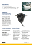
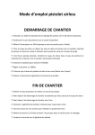
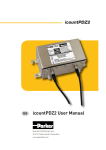
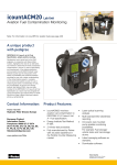
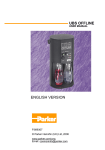
Icount PD
Online Particle Detector
Icount PD
The Icount Particle Detector from Parker represents the
most up-to-date technology in solid particle detection.
The design dynamics, attention
to detail, and small size of the
permanently mounted, on-line
particle detector brings a truly
innovative product to all industry.
•
•
•
•
•
Features and benefits of the
Icount PD include:
Independent monitoring of
system contamination trends.
Early warning LED or
digital display indicators
for Low, Medium and High
contamination levels.
Moisture % RH LED indicator
(optional).
Cost effective solution in
prolonging fluid life and
reducing machine downtime.
Visual indicators with power
and alarm output warnings.
Typical Applications
Mobile Equipment
• Earth Moving Machinery
• Harvesting
• Forestry
• Agriculture
Power Generation
• Wind Turbines
• Gearboxes
• Lubrication Systems
Industrial Equipment
• Production Plants
• Fluid Transfers
• Pulp & Paper
• Refineries
Maintenance
• Test Rigs
• Flushing Stands
The laser based, leading-edge
technology is a cost effective market
solution to fluid management and
contamination control.
• Continuous performance for
dependable analysis.
• Hydraulic, phosphate ester
& fuel fluid compatible
construction.
• Self diagnostic software.
• Fully PC/PLC integration
technology such as:
RS232 and 0-5 Volt, 4-20mA.
Icount PD
Features and Benefits
Diagnostic self check start-up time
5 seconds
Measurement period
5 to 180 seconds
Reporting interval through RS232
0 to 3600 seconds
Digital LED display update time
Every second
Limit relay output
Changes occur +/- 1 ISO code at set limit (Hysteresis ON)
or customer set (Hysteresis OFF)
4-20mA output signal
Continuous
Principle of operation
Laser diode optical detection of actual particulates
Reporting codes
ISO 7 – 21, NAS 0 – 12, (AS 00 – 12 contact Parker)
Icount will also report less than ISO 7, subject to the statistical uncertainty
defined in ISO4406:1999, which is shown in the RS232, reporting results
as appropriate e.g “>6”
Calibration
By recognized on-line methods, confirmed by the relevant International
Standards Organization procedures
Calibration recommendation
12 months
Performance
+/- 1 ISO Code (dependant on stability of flow)
Reproducibility / Repeatability
Better than 1 ISO Code
Power requirement
Regulated 9 to 40Vdc
Maximum current draw
150mA
Hydraulic connection
M16 x 2 hydraulic test points (5/8” BSF for aggressive version)
Flow range through the device
40 to 140 ml/min (optimum flow = 60ml/min)
Online flow range via System 20
Size 0 = 6 to 25 l/min - (optimum flow = 15 l/min)
Inline Sensors
Size 1 = 24 to 100 l/min - (optimum flow = 70 l/min)
Size 2 = 170 to 380 l/min - (optimum flow = 250 l/min)
Required differential pressure
across Inline Sensors
5.8 psi (0.4 bar) minimum
Viscosity range
10 to 500 cSt
Temperature
Operating environment: -20°C to +60°C (-4°F to +140°F)
Storage: -40°C to +80°C (-40°F to +176°F)
Operating fluid: 0°C to +85°C (+32°F to +185°F)
Working pressure
2 to 420 bar (30 to 6,000 PSI)
Moisture sensor calibration
±5% RH (over compensated temperature range of +10°C to +80°C)
Operating humidity range
5% RH to 100% RH
Moisture sensor stability
±0.2% RH typical at 50% RH in one year
Certification
IP66 rated
EMC/RFI – EN61000-6-2:2001
EN61000-6-3:2001
Materials
User friendly construction
Stainless Steel hydraulic block
Viton seals
Dimensions
7.2” x 6.1” x 3.4” (182mm x 155mm x 86mm)
Weight
2.9 lbs. (1.3 kg)
Icount PD
0.6”
(16)
1.5”
(37)
1.9”
(49)
3.4”
(86)
Dimensions / Installation Details
7.2”
(182)
NORMALLY OPEN
NORMALLY CLOSED
COMMON
4.3”
(110)
2.4” CTRS
(60 CTRS)
*Limit Relay Wiring Instructions
Pin #2
Pin #3
Pin #8
0.8”
(21)
2.0”
(52)
6.1”
(155)
2 mounting locations to suit M5 socket head cap screw.
(Screw pack supplied with Icount PD.)
Icount PD flange thickness = 0.4” (10mm)
Maximum Torque 5Nm
M12 Communication Cable: Wiring Configuration
4-20mA
option connections
0-5V/0-3V
option connections
1
NOT USED
NOT USED
2
RS232 Ground (pin 5**)
RS232 Ground (pin 5**)
3
Channel A, ISO 4μm (c)*
Channel A, ISO 4μm (c)*
4
Channel B, ISO 6μm (c)*
or NAS (if selected)
Channel B, ISO 6μm (c)*
or NAS (if selected)
5
RS232 Receive (Pin 3**)
RS232 Receive (Pin 3**)
6
RS232 Transmit (Pin 2**)
RS232 Transmit (Pin 2**)
7
Moisture sensor channel (if fitted)
Moisture sensor channel (if fitted)
8
Channel C, ISO 14μm (c)*
Channel C, ISO 14μm (c)*
Pin
Note: It is the responsibility of the
end user to ensure that the cable’s
braided screen is terminated to a
suitable earth bonding point.
* Optional – refer to the Icount PD
part number specifier section in the
manual.
** A standard USB serial adaptor
can be used with the recommended
9-way D-type connector to convert
RS232 to USB.
*M12 Limit Relay & Alarm Levels: Wiring Configuration
Current loop
option connections
0-5V/0-3V
option connections
1
Product supply 9-40Vdc
Product supply 9-40Vdc
2
4-20mA supply 12-20Vdc
0-5 / 0-3V supply 12-24Vdc
3
Relay (Normally Closed)*** (if fitted)
Relay (Normally Closed)*** (if fitted)
4
Relay (Normally Open)*** (if fitted)
Relay (Normally Open)*** (if fitted)
5
NOT USED
NOT USED
6
NOT USED
0-5 / 0-3V supply 0Vdc
7
Main supply 0Vdc
Product supply 0Vdc
8
Relay (Common)*** (if fitted)
Relay (Common)*** (if fitted)
Pin
Note: If the moisture sensor is
fitted without either option, then
the output is RS232.
Parker recommends that the
mating M12 connector cables
are screened. These cables are
available from Parker through the
ordering information section.
*** Optional – refer to ordering
information section.
The following table can be used to equate the
analogue output to an ISO or NAS Code.
Example: ISO code 12 is equal to 10mA.
Icount PD
Variable mA output settings
mA
4.0
4.5
5.0
5.5
6.0
6.5
7.0
7.5
8.0
8.5
9.0
9.5
10.0
10.5
11.0
11.5
12.0
12.5
13.0
13.5
14.0
14.5
15.0
15.5
16.0
16.5
17.0
17.5
18.0
18.5
19.0
19.5
20.0
ISO V MILLIAMP
Milliamp Output
20.0
18.0
16.0
14.0
12.0
10.0
8.0
6.0
4.0
2.0
0.0
0
1
2
3
4
5
6
7
8
9 10 11 12 13 14 15 16 17 18 19 20 21
ISO CODE
NAS V MILLIAMP
Milliamp Output
20
18
16
14
12
10
8
6
4
2
0
0
1
2
3
4
5
6
7
8
9
10
11
12
13
NAS CODE
ISO
0
1
2
3
4
5
6
7
8
9
10
11
12
13
14
15
16
17
18
19
20
21
**
**
**
**
**
**
**
**
OVERRANGE
OVERRANGE
ERROR
mA
4
5
6
7
8
9
10
11
12
13
14
15
16
17
18
19
20
NAS
00
0
1
2
3
4
5
6
7
8
9
10
11
12
**
**
ERROR
4-20mA output settings
ISO Setting
mA current = (ISO Code / 2) +4
eg. 10mA = (ISO 12 / 2) +4
or
ISO Code = (mA current - 4) *2
eg. ISO 12 = (10mA -4) *2
NAS Setting
mA current = NAS Code +5
eg. 15mA = NAS 10 +5
or
NAS Code = mA current -5
eg. NAS 10 = 15mA – 5
Variable voltage output settings
The variable voltage output option
has the capability of two different
voltage ranges: a 0-5Vdc range as
standard, and a user-selectable
0-3Vdc range. The full list of
commands on how to change the
voltage output is available from
Parker.
The following tables can be used
to relate the analog output to an
ISO or NAS code.
For example, in a 0-5Vdc range,
ISO code 16 is eaual to an output
of 3.5Vdc. In a 0-3Vdc range, ISO
code 8 is equal to an output of
1.0Vdc.
Table relating ISO codes to voltage output
ISO
Err
0
1
2
3
4
5
6
7
8
9
10
11
0-5Vdc
<0.2
0.3
0.5
0.7
0.9
1.1
1.3
1.5
1.7
1.9
2.1
2.3
2.5
0-3Vdc
<0.15
0.2
0.3
0.4
0.5
0.6
0.7
0.8
0.9
1.0
1.1
1.2
1.3
▷▶
cont.
▶▷
ISO
12
13
14
15
16
17
18
19
20
21
22
Err
0-5Vdc
2.7
2.9
3.1
3.3
3.5
3.7
3.9
4.1
4.3
4.5
4.7
>4.8
0-3Vdc
1.4
1.5
1.6
1.7
1.8
1.9
2.0
2.1
2.2
2.3
2.4
>2.45
Table relating NAS codes to voltage output
ISO
Err
00
0
1
2
3
4
5
6
7
8
9
10
11
12
Err
0-5Vdc
<0.4
0.6
0.9
1.2
1.5
1.8
2.1
2.4
2.7
3.0
3.3
3.6
3.9
4.2
4.5
>4.6
0-3Vdc
<0.2
N.S.
0.3
0.5
0.7
0.9
1.1
1.3
1.5
1.7
1.9
2.1
2.3
2.5
2.7
>2.8
Icount PD
Display parameters (ISO 4406/NAS 1638)
Digital display indication
The digital display will show the
actual measured codes, the channel
(μ) size and the user defineable
limits. Note that the channel size
and limits will alternate between
the two.
The moisture sensor reading (%RH)
will also be shown – if the moisture
sensor option is fitted.
The order of trigger for both of the
codes and moisture sensor option
is:
•
Solid digit(s) = code(s) that are
at or below the set point (limit)
•
Flashing digit(s) = code(s) that
are above the set point (limit)
The display for ISO4406 and
NAS1638 are identical. The ISO
display is shown below.
MTD calibrated
Measured ISO codes
Channel sizes/limits
Moisture sensor reading
Automatic light sensor
Error detection
LED display indication
The LED display uses 3 sets of LED for
the indication of ISO 4406 and NAS1638
code figures. Individual code lights will
trigger based on the customer settings.
The order of trigger will be:
•
Solid green = one ISO code, or better, below the set
point (limit)
•
Blinking green = ISO code at the set point (limit)
•
Solid red = one ISO code above the set point (limit)
•
Blinking red = two ISO codes, or more, above the set
point (limit)
In the unlikely event of an error
occurring, the digital display on
the Icount PD will simply display
the actual error code only – i.e.
ERROR 13 (a full list of error codes
is detailed in the Icount PD user
manual).
Moisture sensor output settings
The moisture sensor is an option
that can be included when
specifying the Icount PD. The
moisture sensor reports on the
saturation levels of the fluid passing
through the Icount PD sensing
cell. The output is a linear scale,
reporting within the range of 5%
saturation to 100% saturation.
Saturation
5%
25%
50%
75%
100%
4-20mA
4.8
8
12
16
20
0-3Vdc
0.15
0.75
1.50
2.25
3.00
0-5Vdc
0.25
1.25
2.50
3.75
5.00
Icount PD
Auxilliary Flow Device
This flow control device
automatically compensates for
pressure and viscosity changes,
while maintaining its setting even
as the workload changes.
The pressure compensated, flow
control device (Part Number
S840074) has been developed to
give the Icount PD user greater
flexibility. The flow control device
will enable testing where flow
ranges are outside the Icount PD
specifications (40 – 140 ml/min),
or where pipe diameters do not
allow the Icount PD to be installed.
Simply position the valve to match
the viscosity of the oil you are
testing.
The chart below can be used to
determine the valve position:
The flow control device fits onto
the downstream (outlet) side of
the Icount PD, connecting through
a manifold block, via a self-sealing
quick connection test point and is
fitted with a differential pressure
valve.
Valve Position
3
3.8
4.2
5
cSt Range
up to 100
90 - 200
190 - 320
310 - 500
Example:
If the fluid you wish to analyse has
a viscosity of 50cSt under normal
operating conditions then the
control knob on the Flow Control
Device should be set to valve
position ‘3.’
The flow device will now
automatically control the flow rate
through the IcountPD to within its
working range of 40-140ml/min.
Note: The flow control device will
still operate correctly even with
the high pressure side at 200bar
and the return back to an open
system of 0 bar (DP = 200bar).
Hydraulic Connection Diagram
High Pressure
Line Side
G1/8 ports
either side of
mounting block
4 holes
0.26” (6.60)
Thro’
1.9”
(49.2)
Flow Control
Device
“In”
“Out”
1.5” Ctrs
(38.0 Ctrs)
Actuator
Manual flow rate adjustable via control knob
Mounting type
4 off mounting holes to suit M6 screws (not supplied)
Mounting position
Any
Weight
3.7 lb. (1.7 kg)
Fluid temperature
+41°F to +176°F (+5°C to +80°C)
Ambient storage temperature -4°F to +104°F (-20°C to +40°C)
Viscosity range
20cSt to 500cSt (if lower than 20cSt, contact Parker)
Differential pressure range
5 to 315 bar
Maximum pressure
315 bar
Flow direction
IN to OUT flow control function
Port thread detail
1/8” BSPP (test points not supplied)
Internal seals
Viton
3.2” Ctrs
(80 Ctrs)
OUT
3.5”
(90)
2” (50)
2.4”
(62)
IN
Low Pressure
Return Side
1.8” (46.5)
3.1”
(78.2)
0.8”
(20)
2.3”
(58.2)
P1
3.1”
(78.2)
P2
4.5”
(113.2)
Icount PD
Icount PD
Communication Options
Communication protocol
The IcountPD may be configured
using the Icount PD Setup Utility.
For more direct control of the
device using its communications
protocol, you may also use
the Microsoft Windows®
HyperTerminal program (this
program is not currently supplied
with the Windows Vista™ operating
system).
The communication protocol for
the serial communication link is to
be used with Microsoft Windows
HyperTerminal. The settings are as
follows:
Baud rate . . . . . . . . . . .9600
Data bits. . . . . . . . . . . .8
Parity. . . . . . . . . . . . . . .None
Stop bits . . . . . . . . . . . .1
Flow control . . . . . . . .None
The commands used with this
product are made up of Set, Read
and Start/Stop commands.
• Set commands allow
the value or values of
parameters to be set
• Read commands allow
the value or values of
parameters to be read
• Start/Stop allows the user to
start and stop tests
All commands are sent in ASCII
characters, and the protocol
accepts both upper and lower case
characters as the examples below:
SDF
SdF
Note: A full list of commands is
detailed in the user manual.
Ordering Information
Key
IPD
Fluid Type
1 Mineral
2 Aggressive
3 Aviation fuel
Hazardous areas
4 Aviation fuel
Non Hazardous areas
Calibration
Display
1 ACFTD
2 MTD
3 AS4059
2 LED
3 LCD
Limit
Relay
2 Yes
Communication
Moisture
Sensor
2 RS232/4-20mA
3 RS232/0-5V
1 No
2 Yes
Accessories
Cable Connector Kit
10 Deutsch DT series connector
30 M12, 8-pin plug connector*
Part Number
Mineral
Aggressive
1 Meter Hose Length
B.84.224
B.84.827
2 Meter Hose Length
B.94.802
B.94.801
5 Meter Hose Length
B.84.730
B.84.828
1/4” BSP Test point
P.653109 (M16)
P.843081 (5/8 BSF)
1/8” BSP Test point
P.653110 (M16)
P.853008 (5/8 BSF)
1/8” NPT Test point
P.653512 (M16)
P.853005 (5/8 BSF)
Single Point Sampler
SPS2021
SPS2026
External Flow Device
S840074
Contact Factory
Power Supply
B.84.829
B.84.829
5 meter, M12, 8-pin plug
and socket cable kit*
Contact Factory
Contact Factory
*M12 Cable kit consists of two 5 meter cables to enable all output options
(Communications cable and Relay/Power Supply cable)
© 2008 Parker Hannifin Corporation
Bulletin 2300-425
Parker Hannifin Corporation
Hydraulic Filter Division (USA)
16810 Fulton County Road #2
Metamora, OH 43540 USA
phone 419 644 4311
fax 419 644 6205
email [email protected]
www.parker.com/hydraulicfilter
03/2008