1
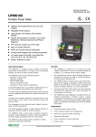
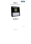
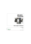
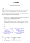
WINTOOL
1UXUDEDAL002
USER'S MANUAL
www.algodue.com
WINTOOL
Power Meter Management Software
USER'S MANUAL
(STANDARD & MODBUS Protocol)
Version 3.00 or Later
EDITION: DECEMBER 2004
This manual can not be reproduced, neither partially nor entirely, without previous authorization from the manufacturer. The manufacturer declines all liability for any damage to people or property caused by incorrect use of
the product. Subject to change without prior notice.
TABLE OF CONTENTS
1 INTRODUCTION . . . . . . . . . . . . . . . . . . . . . . . . . . . . . . . . . . . . . . . . . . 3
1.1
HOW TO USE THIS MANUAL . . . . . . . . . . . . . . . . . . . . . . . . . . . . . . . . . . . . . 3
2 INSTALLATION . . . . . . . . . . . . . . . . . . . . . . . . . . . . . . . . . . . . . . . . . . . 3
2.1
HARDWARE REQUIREMENTS . . . . . . . . . . . . . . . . . . . . . . . . . . . . . . . . . . . . 3
2.2
INSTALLATION ON HARD-DISK . . . . . . . . . . . . . . . . . . . . . . . . . . . . . . . . . . . 4
2.3
RUN AND BRIEF DESCRIPTION . . . . . . . . . . . . . . . . . . . . . . . . . . . . . . . . . . . 4
2.3.1 MAIN MENU . . . . . . . . . . . . . . . . . . . . . . . . . . . . . . . . . . . . . . . . . . . . . . 4
2.3.2 TOOLBAR . . . . . . . . . . . . . . . . . . . . . . . . . . . . . . . . . . . . . . . . . . . . . . . . 5
2.3.3 STATUS BAR . . . . . . . . . . . . . . . . . . . . . . . . . . . . . . . . . . . . . . . . . . . . . 5
3 INSTANTANEOUS VALUES PAGE . . . . . . . . . . . . . . . . . . . . . . . . . . . . . 6
4 MAIN WINTOOL FUNCTIONS . . . . . . . . . . . . . . . . . . . . . . . . . . . . . . . 7
4.1
CONNECTION SETUP . . . . . . . . . . . . . . . . . . . . . . . . . . . . . . . . . . . . . . . . . . 7
4.1.1 HOW TO CONNECT THE INSTRUMENT . . . . . . . . . . . . . . . . . . . . . . . . 7
4.2
ETHERNET INTERFACE . . . . . . . . . . . . . . . . . . . . . . . . . . . . . . . . . . . . . . . . . 8
4.3
INSTRUMENT SETUP . . . . . . . . . . . . . . . . . . . . . . . . . . . . . . . . . . . . . . . . . . . 9
4.3.1 SETUP PARAMETERS WINDOW . . . . . . . . . . . . . . . . . . . . . . . . . . . . . . 9
4.3.2 INPUTS AND OUTPUTS SETUP . . . . . . . . . . . . . . . . . . . . . . . . . . . . . . 13
4.3.3 TIME OF USE SETUP WINDOW . . . . . . . . . . . . . . . . . . . . . . . . . . . . . . 16
4.4
INFORMATION WINDOW . . . . . . . . . . . . . . . . . . . . . . . . . . . . . . . . . . . . . . . 17
4.5
LANGUAGE . . . . . . . . . . . . . . . . . . . . . . . . . . . . . . . . . . . . . . . . . . . . . . . . . . 18
4.6
EXIT
. . . . . . . . . . . . . . . . . . . . . . . . . . . . . . . . . . . . . . . . . . . . . . . . . . . . . . 18
5 CONNECTION CABLES . . . . . . . . . . . . . . . . . . . . . . . . . . . . . . . . . . . . 18
WINTOOL
3
1 INTRODUCTION
The function of this application is to program the analysers in the work-area, monitoring the
electrical measurement.
The software allows:
• monitoring of the electrical parameters acquired by the instrument
• programming of the most important functioning parameters
WINTOOL works on a IBM-compatible PC in a Microsoft Windows® 95 / 98 / 2000 / NTTM 4.0
/ XP environment.
WINTOOL can manage the UPM / UPT and similar series instruments.
1.1 HOW TO USE THIS MANUAL
This user’s manual has been prepared for a correct use of the WINTOOL monitoring
software.
In the first part there is a detailed description of the hardware features and the procedures to
follow for the installation of the software.
The following part describes the software use.
2 INSTALLATION
Before starting to use WINTOOL on the computer, it is important to carry out the whole
installation procedure.
In this chapter the PC hardware requirements and the installation procedure are described.
2.1 HARDWARE REQUIREMENTS
Before using WINTOOL it is necessary to verify if the computer is compatible with the
software.
Suggested configuration:
• IBM-compatible PC (Pentium 2 or higher recommended)
• Operating system Microsoft Windows® 95, 98 , 2000, NTTM 4.0 Workstation or XP
• At least 10 MB of free space on the hard disk
• SVGA graphic boards
• Mouse and keyboard
• Serial RS232 communication port and/or LAN connection
4
USER'S MANUAL
2.2 INSTALLATION ON HARD-DISK
Procedure for the installation of the program on the hard-disk.
1. Turn on the computer and wait until Microsoft Windows® environment has been loaded.
2. Insert the provided Disk into your system's CD Reader.
3. Select Run from the Windows START button.
4. Type "X:\SETUP" and press <ENTER>, where X is the computer CD-ROM drive letter
where the disk was inserted.
It will automatically carry out the installation program.
5. At the end of the setup the WINTOOL program group will appear.
6. To start the program double-click on the WINTOOL icon.
2.3 RUN AND BRIEF DESCRIPTION
For the connection modes of the WINTOOL it is necessary to refer to the user's manual of
the instrument. Our advice is to use isolated converters to avoid ground loop occurencies that
could damage the computer.
The window which appears automatically at the moment of the program activation allows the
selection of the communication parameters. For more details, see section 4.1
2.3.1 MAIN MENU
The main menu bar items are the following:
Instrument
Help
Different setup functions.
Help and about functions.
Instrument menu
The Instrument menu offers the following items:
Connection Setup
Ethernet Interface
Displays the window which enables the setup of the communication
parameters (the logical number of the connected meter, the TCP/
IP connection parameters and the protocol type)
Displays the window that enables the setup of the Ethernet interface
parameters for a desired instrument
WINTOOL
Setup
5
Displays the window that enables to program the instrument
connected to WINTOOL
Displays information about the connected instrument and the
connection status
Allows to select one of the available languages
Exit from WINTOOL
Information
Language
Exit
Help menu
The Help menu offers the following items, which provide you with assistance about this
application:
Index
Help
About
Index to topics on which you can get help.
Help about the currently displayed page.
Information about WINTOOL (version and copyright).
2.3.2 TOOLBAR
The toolbar is displayed on the top of the main window, under the main menu bar. The toolbar
provides quick mouse access to WINTOOL functions.
Short cut
Button
Operation
[Shift + F10]
"Information" window
[Shift + F9]
"Instrument Setup" window
[Shift + F1]
"Connection Setup" window
[Alt + F4]
Exit from WINTOOL
2.3.3 STATUS BAR
The status bar is displayed at the bottom of the WINTOOL window.
The left area of the status bar describes the actions of menu items, when keyboard is used to
select menu items. This area similarly shows messages that describe the actions of toolbar
buttons as you press them, before releasing.
The right area of the status bar gives different information on the connected instrument:
• serial number
• instrument type
• wiring diagram
• used communication port
• communication speed
6
USER'S MANUAL
3 INSTANTANEOUS VALUES PAGE
The main page is displayed automatically at the start of the program, it displays all the variables
measured by the connected instrument in realtime. The displayed variables depend on
measurements carried out by the connected instrument.
The refresh time of the values depends on the communication speed between the PC and the
instrument.
WINTOOL
4
7
MAIN WINTOOL FUNCTIONS
4.1 CONNECTION SETUP
This window enables to setup all the communication parameters between the PC and the
instrument.
Fields description:
Line Speed
Parity
PC Port
TCP/IP
IP Address
Port
Modbus
Serial Number
Address
Communication speed selection in case of COM Port connection:
300, 600,1200, 2400, 4800, 9600, 19200, 38400 or 57600 baud
Parity bit: None, Even, Odd
PC communication port used for the connection
Select this field in case of communication via Ethernet port
IP Address of the instrument to be connected
Reserved (set always on 3000)
Set this checkbox in case of MODBUS protocol and select ASCII
or RTU mode. If this box is not checked, WINTOOL will use
STANDARD protocol
Serial number of the instrument to be connected, disabled in case
of MODBUS protocol
Logical number of the instrument to be connected. Needed only
for MODBUS protocol.
4.1.1 HOW TO CONNECT THE INSTRUMENT
The UPM / UPT and similar series instruments are provided with a RS232 and / or RS485,
and/or Ethernet communication port.
The instruments with RS232 port can be connected directly to the PC COM port.
The instruments with RS485 port cannot be connected directly to the PC COM port, a converter
module (eg. CV3285M) must be inserted.
The instruments with Ethernet interface must be connected with a CROSS LAN cable directly
to PC, or via a HUB or SWITCH.
To run the search function in STANDARD protocol, cancel the Serial Number field and press
Search button. WINTOOL starts to search the connected instrument, scanning all baudrates
started with the value set when the search was started. This function is not available for
MODBUS protocol.
The serial number, which appears in the Serial Number field, is the one relative to the last connected
instrument, and to connect a new one the old serial number must be cancelled or changed.
8
USER'S MANUAL
4.2 ETHERNET INTERFACE
This window allows to set the parameters of Ethernet interface for a selected instrument. This
setup will not change the parameters of the PC's LAN interface.
Fields and buttons description:
IP Address
IP Address for the selected interface (selection made by the MAC
address field).
Subnet Mask
Subnet Mask according to the local network setup.
Gateway
Gateway IP Address.
Listen Port
Reserved, always on 3000.
Serial options
Communication parameters between the Ethernet interface and
the instrument.
Web-Server Message Text message (max.50 characters) displayed in the HTML web
page in case of enabled webserver function.
Direct cfg
Set this checkbox, in case the interface is not connected in the
local network, but is available via a gateway. For example, if a NAT
function is available for gatewaying to the internet, the interface
can be reached setting in the Address field the NAT-ed and IP
Address.
LAN cfg
Set this checkbox, if the interface is connected to the local network
(LAN). In this case after a Search, MAC Addresses for all the
interfaces will be available.
ATTENTION! The communication parameters in this field must be set to
the same values set in the instrument. Otherwise, the interface cannot
communicate with the instrument.
Search button
Update button
Dial-Up button
Cancel button
Search the available interfaces in the local network, or search the
interface in case of direct connection. After the board is found,
all actual setup parameters will be displayed in the fields.
Updates the new parameters in the interface.
Start a dial-up connection to internet, if Dial-up connections are
already enabled on the PC.
Exit from this window.
WINTOOL
4.3
9
INSTRUMENT SETUP
This window allows the programming of the main parameters of the connected instrument.
Buttons description:
Setup button
Open the main parameters setup window for the connected
instrument.
Input/Output Setup button Open the I/O setup window for the connected instrument
(eg. digital outputs, analog outputs, digital inputs..).
Time of Use button
Open the timebands setup window for the connected
instrument, defining the 3 tariffs setup for the whole year
for the tariffar energy counting. The button is enabled only
when the meter is equipped with this function.
CPU2 Mode.. button
Refer to the specific "VDROP/VMAX" manual of the instrument
(optional)
Note. The disabled buttons are available only in DEDALO SP program.
4.3.1 SETUP PARAMETERS WINDOW
Note: the fields present in all different setup windows depend on the connected instrument
model.
The Setup button is active when an instrument is connected and allows the main parameters
setup.
See the instrument User's Manual for the complete description of the parameters setup by
the user through serial port.
Please note that if you change the Serial line parameters or the logical number of the connected
instrument, WINTOOL automatically updates the PC serial line parameters settings, to mantain
the connection with the instrument.
10 USER'S MANUAL
This window enables the setup of the main parameters of the connected instrument.
Fields and buttons description:
Line speed
Communication speed of the connected instrument.
Parity
Parity bit.
Instr. COM1/2
Select the instrument COM port.
Logical Number
The logical number of the connected instrument.
Ethernet button
Open the Ethernet Interface window.
Date
Date of the connected instrument realtime clock.
Time
Time of the connected instrument realtime clock.
Format
Date and time format.
Week Day
Day of the week.
Manual
Pressing this button, the manually set data and time fields content
will be programmed.
PC Synchro
Pressing this button, the date and time of the PC will be
programmed.
CTs Ratio
Note. If the connected instrument does not have RTC, the date
and time fields are disabled.
External current transformer ratio.
WINTOOL 11
PTs Ratio
External power transformer ratio.
Curr. Inp. FS [A]
Instrument current input fullscale value.
Wiring
Wiring mode.
Pic
Wiring mode diagram.
DMD Time [min]
Select the integration time for demand values calculation, in
minutes, valid only for Fixed and Slide modes. In case of COM or
DIx modes EXT will be displayed (EXTERNAL SYNCHRO), and
this field is disabled.
Mode
Select the demand values calculation mode.
Fixed demand values calculated with a fixed window; the values
are recalculated each time at the end of the time period
set by DMDTime
Slide demand values calculated with a sliding window; the
values are recalculated after each minute using a sliding
integration window set by DMD Time
COM demand values calculation synchronized by a serial
command
DI1
demand values calculation synchronized by a pulse on
digital input1
DI2
demand values calculation synchronized by a pulse on
digital input2
DI3
demand values calculation synchronized by a pulse on
digital input3
DI4
demand values calculation synchronized by a pulse on
digital input4
Instr. Language
Select the instrument language.
Light ON time [s]
Instrument backlight.
THD Mode
THD mode. Available choices: USA, EUROPA.
Synchro Frequency [s] Synchronization of the measurement with the mains frequency.
Synchro Mode
Synchronization Mode.
• AUTO: the instrument is automatically hooked to the mains
frequency measured on phase L1 (when the frequency and
voltage values are within the measuring range)
• FIXED: Set a fixed frequency value for the measurement
12 USER'S MANUAL
Reset button
The Reset window will be opened, containing a list with the items
to be cleared.
Fields and buttons description:
Energy counters reset
Digital In. Counters reset
Select this checkbox to clear the energy counters.
Select this checkbox to clear the digital input
counters.
Min/Max Reset
Select this checkbox to clear the minimum and maximum
values.
Pdmd Peak & Sdmd Peak R.. Select this checkbox to clear the demand peak values
of active and apparent power.
Idmd Peak Reset
Select this checkbox to clear the demand peak values
of system current.
Timeband Counters reset
Select this checkbox to clear the timeband counters.
MIN/AVG/MAX Recording Delete Select this checkbox to clear all the recordings.
Daily Energy Counters Reset Select this checkbox to clear the daily energy
counters
Event LOG Delete
Select this checkbox to clear the Event LOG
recordings.
Captured Waveform Delete
Select this checkbox to clear the captured
waveform.
This window can change according to the instrument type/model. Here below a description
of the missing items which are displayed only with another instrument type connected:
Delete Data Profiles
Select this checkbox to clear the profile pages.
Reset Recorded VDROP Events Select this checkbox to clear the recorded VDROP
events.
After OK button is pressed, a confirmation window will be displayed. If this warning message
is confirmed, the selected items will be erased.
All button
Update button
Cancel button
All set values in the fields are uploaded to the instrument.
The instrument is updated only with the values that have been
modified
Exit from the setup window without changing the instrument setup
WINTOOL 13
By clicking on All or Update button an upload progress bar will be displayed.
4.3.2 INPUTS AND OUTPUTS SETUP
Please refer to the instrument user’s manual for a full description of the parameters the user
can program by using the serial port.
The Input/Output Setup button accesses to the I/O channel selection window.
To program the parameters of any one of the listed items, just select it by double-clicking or
by marking it with the mouse or the arrow keys and confirming with OK button.
Digital inputs setup
Fields description:
Set
The weight of the input pulse value
Once the setup is carried out, press OK button, and the new values will be uploaded in the
instrument.
14 USER'S MANUAL
Digital outputs setup
Fields and buttons description:
Variable
Mode
Delay
Hysteresis
Set
FS button
Measurement variable to be associated with the Digital Output.
1) Pulse - in case of energy type variables
2) High - high treshold alarm mode
3) Low - low treshold alarm mode
If pulse mode is selected, it sets the length of the pulse (max 250
ms).
If the High/Low mode is selected, it sets the delay time, starting
from the moment when the threshold has been overtaken, and
the moment when the output changes state.
Only for High/Low mode and sets the percentage value of the
hysteresis referred to the threshold value (max. 99 %).
If pulse mode is selected this value sets the weight of each emitted
pulse. If the High/Low mode is selected, it sets the threshold
value.
The treshold value can be set in two modes, by setting the
percentage value referred to the fullscale of the selected variable,
or by setting the absolute value.
Opens an Information window with full scale values of the connected
instrument (Voltage, Current, Power).
WINTOOL 15
Analog outputs setup
Fields and buttons description:
Variable
Mode
Min
Max
Example.
Measurement variable to be associated with the Analog
Output.
1) Monodirectional 0-20 mA
2) Monodirectional 4-20 mA
3) Bidirectional 0-20 mA
4) Bidirectional 4-20 mA
Minimum value of the selected variable to be associated to the
minimum output current of the Analog Output (0 or 4 mA).
Maximum value of the selected variable to be associated to the
maximum output current of the Analog Output (20 mA).
Opens an Information window with full scale values of the connected
instrument (Voltage, Current, Power).
Variable = V1
Mode = Monodirectional 0÷20 mA
FS = 433 V
Min = 50% (50% x 433V = 216,5V)
Max = 70% (70% x 433V = 303,1V)
For 216,5V * V1* 303,1V the Analog Output current will be in range
0÷20 mA.
WINTOOL 16
4.3.3 TIME OF USE SETUP WINDOW
The Time of Use button accesses to the timebands setup window.
Buttons description:
Schedule1..10 buttons
Setup button
Load button
Save button
All button
Cancel button
Setup tariff schedule 1...10.
Holidays setup.
The timebands saved in a profile are loaded.
The timebands setup is saved in a profile that can be reloaded.
Uploads the Timebands setup in the instrument.
Leaves timebands setup without saving the modifications.
Fields description:
Time 1...8
Defines the start time (hh : mm) of each tariff time interval within a day.
Up to eight variations in a day can be set.
WINTOOL 17
Rate
For each time interval it is possible to setup three tariff levels (1, 2, 3).
Select tariff level 0 to end the daily programming. If tariff level 0 was
selected, all the following programmed values are not considered.
Note. The tariff level 3 is attributed entirely to the days not selected into
a tariff period.
Month/Day button Open a window where it is possible to assign a schedule for each day of
the month
4.4
INFORMATION WINDOW
This button displays a window where information about the connected instrument is
reported.
Button and fields description:
Model
Outputs
Harmonics
Connected instrument type or model.
Type and number of inputs and outputs mounted on the instrument
(if available).
Measured harmonics order (if available).
WINTOOL 18
Memory
Address
Com/IP
Serial Number
Firmware Rel.
Build Year
Comm. status
Cancel button
4.5
Memory quantity of the instrument (if available).
Logical number of the connected instrument.
COM port and Baudrate of the PC when the instrument is connected
or the IP Address.
Serial number of the connected instrument.
Firmware release of the instrument.
Built year.
GREEN = communication ok;
RED = not connected.
Exit from this window.
LANGUAGE
Select the display language for WINTOOL.
4.6
EXIT
Use this button to exit from WINTOOL.
5
CONNECTION CABLES
For the connection cables refer to the User's Manual of the instrument.
Via Passerina, 3 / a - 28010 FONTANETO D'AGOGNA (NO) - ITALY
http: // www.algodue.com - E mail: [email protected]