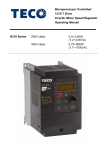
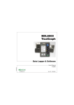
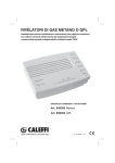
1
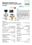
Technical Information 1SAUUPM6K103 Apr 2005 UPM6100 Portable Power Meter 4MBytes Removable Memory Card for Data Logging Integrated Printer (Option) Large Graphic LCD Display with Excellent Visibility Graphic Representation of Voltage and Current Waveforms, Harmonic Spectrum and Phasor Diagrams FFT Harmonic Analysis up to 50th Order Sags and Swells Detection Power and Current Demand Calculation Compact and Rugged Case Carrying Accessories UL Listed Under UL61010B-1 and CAN/CSAC22.2 No.1010.1-92, File #E231725 Dedalo Software Included General Description Benefits The UPM6100 is a portable analyser suitable for electrical parameters measurement on single- and three-phase systems, as well as on direct current systems. • The UPM6100 is suitable for low, medium and high voltage measurement. It can be connected directly up to 600VAC L-L or through PTs for higher voltage. The UPM6100 performs the following functions: - wattmeter / energy meter - harmonics analyser - historical data logger - network anomalies recorder - calculation of Power Factor compensation • The measurement current inputs flexibility allows the instrument to connect any type of current tranducers, including flexible Rogowski coils. • Via communication port it is possible to read and log on a PC all the readings and download the stored data. The UPM6100 offers complete and accurate information about circuit loading; it calculates neutral current and performs load trending. All this data is essential for network overloads detection and circuit optimization. • The wide range of available printouts allows to print the results on-site in graphical and tabular form, without the need for a laptop. Once the target Power Factor value is set, the instrument calculates the capacitor bank value necessary for compensation on real time. • The UPM6100 includes 4Mbytes nonvolatile memory for metered parameters, min/max values, energy consumption and harmonics. The recorded data allows to generate on a PC consumption profiles, logged values trends, cost allocation and reports as well as to identify critic values. A simple menu structure makes the instrument easy to use and it allows a quick check of the instrument set-up and memory status. Five languages can be selected easily: English, German, Italian, French and Spanish. Applications The LED backlighted display is highly efficient therefore it guarantees perfect visibility in all light conditions. • Individual machine load profiling • Power demand analysis and management The UPM6100 offers a wide range of graphic functions: waveform, phasor diagram, harmonic content and profiles of the daily energy consumption with min / max values. • Harmonics, sags and swells monitoring • Capacitor bank sizing • Power distribution circuits monitoring • Energy audits The UPM6100 is the portable solution suitable for utilities, industry and domestic customers. ENERGY MEASUREMENT AND CONTROL www.algodue.com 2 UPM6100 - Portable Power Meter among voltage, current, power, PF and frequency. The data is viewed on the PC according EN50160 standard. Main Features Measurements • Three-phase 3-wire or 4-wire unbalanced load operation, single-phase and direct current. • Direct measurement up to 600 (750)VAC • The instrument can accept different signals from any type of measuring transducer, including flexible Rogowski transducers. The required current channel type is easily selectable by the instrument menu. This flexibility allows to connect the following current tranducers: - voltage output clamps (1, 2, 3VAC-DC full scale) - current output clamps (1, 5AAC full scale) - Rogowski flexible clamps (40 or 100mV/kA) - direct insertion up to 600VAC (1, 5, 20AAC full scale) - current tranducer signals (1, 2, 3, 10VAC-DC full scale) • A fourth current input is also provided specifically for the measurement of earth leakage current • True RMS metering provides accurate measurement even by distorted waveform • Fully bi-directional, four-quadrant readings. 10 energy counters are available, the apparent power/energy is splitted in four counters: import lagging, import leading, export lagging, export leading • Volts, Amps, Power, PF, Frequency, Energy, Min/Max values, Demand, Harmonics, etc. The full version instrument provides more than 600 measured/calculated parameters and shows on the LCD more than 30 graphical pages Power Quality • Individual & total harmonic distortion for voltage and current up to the 50th order. The harmonic content is represented like even, odd and total • CPU2 option - the co-processor board perfoms the simultaneous high-resolution sampling of voltage and current, allowing the cycle-by-cycle power analysis for 50/60 Hz lines. The CPU2 board supports different application like: VDROP, VMAX, WCAP... (see below). The instrument with CPU2 board performs at the same time the wattmeter functions, the harmonic analysis, the basic recording function and the selected cycle-by-cycle power analysis function. • VDROP option - sags & swells detection on L-N voltages with half cycle resolution (10ms @ 50Hz). Pre- and posttrigger logging (100 +100 half cycles RMS values). The detected events are recorded and a relay output can be activated when a voltage anomaly occurs. The data is viewed on the PC according EN50160 standard. • VMAX option - two functions are selectable: VDROP (previous paragraph) and Min/Avg/Max values calculation and recording with one cycle resolution (20ms @ 50Hz). This function allows to record up to 10 parameters selected • WCAP option - advanced waveform capture function on currents and L-N voltages. The instrument can store up to 10 + 200 waveforms before and after a threshold overcome, with a resolution from 8 to 32 samples (depending on the number of waveforms). The WCAP option includes a second selectable function: Min/Avg/Max values calculation and recording (see previous paragraph) Recordings • 4MBytes removable flash card memory for data storage • Up to 10 programmable recordings with different start and stop time. Different type of recordings can be chosen: - import/export active, reactive and apparent power demand with programmable average time. The average period can be syncronized by a digital input - instantaneous read values selected between the main parameters. The recording interval time is programmable between 1 and 9999 seconds - instantaneous min/max values measured during the recording interval time. The recording interval time is programmable between 1 and 9999 minutes - voltage and current harmonic values measured during the recording interval time. The recording interval time is programmable from 1 to 60 minutes • Time-of-Use (TOU) programmable data recording. The TOU function stores the energy consumption in different registers according the programmed time-scheme. A group of 120 registers give the situation of the previous and current day, and of the previous and current month. This feature is designed to fit different tariff structures. It’s possible to program up to 10 daily tariff schedules containing up to 3 tariffs and 8 tariff changes. Each schedule can be assigned to the days of the week and months as requested. Up to 20 holidays can be assigned to the lowest tariff. A diagnostic algorithm checks and notifies any setup overlapping. • Event, alarm and digital outputs ON/OFF recording. The instrument records the status change of 8 programmable set points, the digital outputs ON/OFF and the instrument supply ON/OFF. All the events are integrated by date and time reference • The CPU2 option includes 1MBytes non-volatile data memory. Depending on the CPU2 configuration the following information (already described in the “Power Quality” paragraph) can be recorded: - sags and swells events (VDROP option). The occurring dips and overvoltage over a programmable threshold are detected and the instrument records the date and time of the event, the lenght and the RMS value of 100 +100 half-cycles before and after the event - min / avg / max values of the main measured parameters with continuous sampling and 1 cycle minimum ENERGY MEASUREMENT AND CONTROL www.algodue.com 3 UPM6100 - Portable Power Meter resolution for RMS calculation. The resolution is programmable between 1 and 99 cycles to simulate the recorder response time as needed. The programmable average time defines the time interval between recordings - more than 200 waveforms when a programmable threshold is overcome (WCAP option). The instrument records up to 10 + 200 waves before and after the trigger, with the time reference. The resolution is programmable from 8 to 32 samples / cycle. Communication • No.1 RS232 communication serial port. • Communication speed programmable up to 57.600 bps • Dedalo software enables remote viewing of measured values or data download using an external PSTN / GSM modem or an Ethernet adapter Printer • 40-colums built-in graphic printer. A wide range of printouts can be manually made or programmed with a fixed time interval. The main available printouts are: - manual hard-copy of the screen - automatic printout with programmable time interval of 6 values selected among the main measured parameters - graphic trend with programmable time interval of 5 values selected among the main measured parameters - daily histogram of the power demand (at 00:00) - voltage interruptions longer than 20-30msec are detected and printed with a resolution of 0.1 s Inputs & Outputs • No.1 digital output for alarm tripping or energy pulsing. The digital output can be programmed as alarm signal when an overvoltage or a dip occurs • No.1 active analog output 0-20 or 4-20mA. The output is programmable as requested for the re-emission of one of the main measured parameters • Four optoisolated digital inputs for pulse counting or triggering Power Supply • 85- 250VAC or 110 - 250VDC without any need for operator to change the voltage selection • Internal battery allows more than 3 hours operation - manual printout of the instantaneous values, harmonics, daily histogram of the power demand, min / max values, Time of Use counters, instrument setup WCAP - Waveform capture examples Current load variation - The trigger is on current RMS value, the resolution is 1 cycle. Are represented 5+30 waves before and after the trigger, the sampling is 8 samples / cycle. Voltage drop - The trigger is on voltage RMS value, the resolution is 1 cycle. Are represented 2+10 waves before and after the trigger, the sampling is 32 samples / cycle. ENERGY MEASUREMENT AND CONTROL www.algodue.com 4 UPM6100 - Portable Power Meter STORED DATA INSTANTANEOUS MEASUREMENTS PHASE VOLTAGE VL1-N - VL2-N - VL3-N [V] LINE VOLTAGE SYSTEM ACTIVE ENERGY [Wh] VL1-L2 - VL2-L3 - VL3-L1 [V] SYSTEM APPARENT ENERGY (LAGGING) [VAh] V [V] SYSTEM APPARENT ENERGY (LEADING) SYSTEM VOLTAGE LINE CURRENT SYSTEM LAGGING REACTIVE ENERGY [varh ind] I [A] SYSTEM LEADING REACTIVE ENERGY [varh cap] SYSTEM CURRENT POWER FACTOR PFL1 - PFL2 - PF L3 SYSTEM POWER FACTOR PF COS Ø S [VA] ACTIVE POWER PL1 - PL2 - PL3 [W] SYSTEM ACTIVE POWER P [W] REACTIVE POWER QL1 - QL2 - QL3 [var] SYSTEM REACTIVE POWER Q [var] FREQUENCY f [Hz] DEMAND PAV - QAV- SAV - IAV - IL1AV - IL2AV - IL3AV- INAV IL1 - IL2 - IL3 [A2s] THERMAL CURRENT VOLTAGE THD (Total, Even, Odd) THDL1 - THDL2 - THDL3 [%] CURRENT THD (Total, Even, Odd) THDL1 - THDL2 - THDL3 [%] FFT ANALYSIS 50th VL1-N - VL2-N - VL3-N - IL1 - IL2 - IL3 [%, V, A] FFT ANALYSIS 50th + VOLTAGE AND CURRENT THD (Total) UNBALANCE IN [%, V, A] V,I [%] PHASE REVERSAL 123 / 132 REAL TIME CLOCK Date, Time EARTH LEAKAGE [A] [0C, 0F] TEMPERATURE [V,A, W, VA, var, PF] PAV - QAV - SAV - IAV - IL1AV - IL2AV - IL3AV- INAV PROGRAMMABLE RECORDINGS POWER DEMAND (BI-DIRECTIONAL) PAV - QAV- SAV INSTANTANEOUS VALUES [V,A, W, VA, var, PF, Hz, THD] INSTANTANEOUS MIN/MAX VALUES [V, A, W, VA, var, PF] [V, A - up to 50th] HARMONICS EVENT CAPTURE 8 threshold, outputs, aux power supply [ON/OFF] SAGS AND SWELLS (VDROP) [V - 10ms resolution] MIN / AVG / MAX VALUES (VMAX)(1) [V, I, P, Q, S, f - 20ms resolution] WAVEFORM CAPTURE (WCAP) VL1-N - VL2-N - VL3-N or I L1 - IL2 - IL3 ADVANCED FEATURES TIME OF USE (TARIFF REGISTERS) [Wh, VAh, varh] CALCULATION OF PF COMPENSATION Capacitor bank [kvar] [Wh, VAh, varh, m3, litres, etc.] DIGITAL INPUTS COUNTERS V. DROPS ON AUX POWER SUPPLY Date,Time,lenght (on printer - 0,1s res.) = Standard ( = Bi-directional value) = Optional = Extended Measurement Package (1) Programmable every 1, 5, 10, 15, 30, 60 min - Maximum 10 parameters selected among voltage, current, power, PF, frequency (1) It is possible to set 10 different start/stop corresponding to 10 different recordings (2) The measurements are carried out with continuous sampling Programmable Recordings Detail BASIC VERSION PEAK VALUES WITH TIME REF. SL1 - SL2 - SL3 [VA] SYSTEM APPARENT POWER OPTIONS MIN / MAX VALUES WITH TIME REFERENCE DPFL1 - DPFL2 - DPF L3 APPARENT POWER [VAh] IL1 - IL2 - IL3 - IN [A] TYPE OF RECORDED DATA RECORDING INTERVAL START/STOP RECORDING (1) RECORDED PARAMETERS POWER DEMAND 1, 5, 10, 15, 30, 60 minutes PROGRAMMABLE Active, Reactive Inductive, Reactive Capacitive, Apparent (IMPORT) MINIMUM / MAXIMUM values from 1 to 9999 minutes PROGRAMMABLE V - VL1-N - VL2-N - VL3-N - I - IL1 - IL2 - IL3 - P - S -Q - PF - Demand values INSTANTANEOUS VALUES (Snapshots) from 1 to 9999 seconds PROGRAMMABLE V - VL1-N - VL2-N - VL3-N - VL1-L2 - VL2-L3 - VL3-L1 - I - IL1 - IL2 - IL3 - IN PF - PFL1 - PFL2 - PFL3 - Cosø - CosøL1 - CosøL2 - CosøL3 - S - SL1 - SL2 - SL3 P - PL1 - PL2 - PL3 - Q - QL1 - QL2 - QL3 - F - THD V - THD I - PAV - QAV - SAV HARMONICS 1, 5, 10, 15, 30, 60 minutes PROGRAMMABLE SAGS AND SWELLS 10ms - VDROP (2) When event occurs CONTINUOUS VL1-N - VL2-N - VL3-N MIN / AVG / MAX values 20ms - VMAX (2) from 1 to 999 seconds PROGRAMMABLE Max 10 values selected among voltage, current, power, frequency When event occurs CONTINUOUS VL1-N - VL2-N - VL3-N or IL1 - IL2 - IL3 WAVEFORM CAPTURE 20ms - WCAP (2) VL1-N - VL2-N - VL3-N - IL1 - IL2 - IL3 - (IN ENERGY MEASUREMENT AND CONTROL ) www.algodue.com UPM6100 - Portable Power Meter 5 Specifications Power supply Rated voltage: Consumption: Backup battery Voltage inputs Maximum measurable voltage: Input impedance: Burden: Frequency: Current inputs From isolated tranducers: Direct inputs: From Rogowski coils: ACCESSORIES 85 ÷ 250 Vac 50/60Hz or 110 ÷ 250 Vdc 30VA max during printout and recharge Rechargeable NiMh battery 12V 1,5Ah approx. (more than 3 hours without printing) 600 (750)VAC-DC max L-L >1.3 MOhm max 0.15 VA per phase 45 ÷ 65 Hz + direct current 1, 2, 3, 10VAC-DC programmable Input impedance: >150 kOhm 1, 5, 20(25)ARMS programmable Minimum measurable current: 20mA Input impedance: 0,05 Ohm approx. Insulation voltage: 600(750)VRMS max L-L 700, 3000ARMS programmable (40mV/kA) Input impedance: 15 kOhm Typical accuracy Voltage: Current: Active power: Power factor: Active energy: Frequency: Temperature: ± 0.2% reading ± 0.05% full scale ± 0.2% reading ± 0.05% full scale ± 1% reading ± 0.1% full scale (PF=1) 1% reading (0.5 inductive - 0.8 capacitive) 1% reading (0.5 inductive - 0.8 capacitive) ± 0.05% reading ± 2 digits from 45 to 65 Hz ± 20C @ 0 ÷ 550C - 10min after turn-on Display and operating controls Display: Keypad: Backlighted graphic LCD display128 x128 dots No.8 functional push-buttons + ON/OFF Data memory Type: RS232, optoisolated, 300 to 57600 bps Real Time Clock Type: Accuracy: with battery backup ± 30 ppm Digital output (Option) Type: No.1 isolated Optomos (50V - 300mAAC-DC) Resolution: Accuracy: No.1 isolated configurable 0÷20 or 4÷20mA maximum load = 300 Ohm 16 bits typical accuracy of the instrument (see above) Digital inputs (Option) Type: No.4 isolated, for voltage-free contacts Environmental conditions Operating temperature: Storage temperature: Relative humidity: from -10 oC to +55 oC from -20 oC to +70 oC 80% max. without condensation Mechanical characteristics Material: Protection degree: Size: Weight ABS shock-proof carrying case: IP54, measuring sockets: IP21 420 x 340 x 210 (mm) 6kg approx. without accessories Standards compliance Safety: EMC: 20 / 200A Clamps 4 MBytes removable Flash Card 1 MByte non-volatile (CPU2 option) Communication port Type: Analog output (Option) Type: 1000A Clamps cUL listed under UL61010B-1and CAN/CSA-22.2 No.1010.1-92, File # E231725 73/23/EEC , 93/68/EEC directives, EN61010.1 89/366/EEC directive and following modifications 93/31/EEC and 93/68/EEC, EN50081-2, EN50082-2, EN61326/A1 ENERGY MEASUREMENT AND CONTROL 700 / 3000A Clamps Current Cables Flash Card Reader www.algodue.com 6 UPM6100 - Portable Power Meter UPM6100 Connection Panel Current inputs Auxiliary power supply Fuse Voltage inputs 85 - 250 VAC or 90 - 250 VDC Voltage interruptions longer than 20-30msec are detected and printed with a resolution of 0,1 s. Instrument power supply circuit protection. Direct connection up to 600VAC (750). Above this value the use of voltage transformers is necessary. VT ratio's can be programmed. The instrument can process measurements from current clamps or other transducers with 1, 2, 3 or 10V full scale outputs. Inputs are not isolated; it is always necessary to connect transducers with double insulation according EN61010-1 safety standard. Flexible Rogowski transducers can be directly connected to the inputs without adaptors. The programmable full scales are 700 and 3000A. Earth leakage input A dedicated input, for measurement of earth leakage current by 0-1V clamps or directly from 1000 turns split-core CT. Inputs for direct connection Isolated inputs for direct connection of voltages up to 600(750)V L-L. Maximum current 20 (25)A RMS. These inputs can be programmed for use with transducers with 1 and 5A output value (clamps or current transformers). Serial interface RS232 Temperature sensor Digital output (option) The UPM6100 is provided with serial communication port RS232 to connect to a PC, modem or Ethernet gateway. Detects and displays the environmental temperature. No. 1 optoisolated output that can be programmed for energy pulse emission or alarm. Analog output (option) Digital inputs (option) No. 1 optoisolated active output that can drive the load with no need for an external power supply. It can be programmed as 0-20 or 4-20mA and associated to one of the main instantaneous values. No. 4 isolated inputs for voltagefree contacts. Can be used for energy pulses counting, demand syncronization or status indication (according to installed options). Size mm Printouts Examples 210 Printout of the daily 15' power demand histogram at midnight. 340 42 0 Print screen of numerical and graphic pages Automatic printout with a time interval of 10". Graphic printout of five variables (V, A, kW, kvar,f). ENERGY MEASUREMENT AND CONTROL www.algodue.com 7 UPM610 0 - Portable Power Meter Wiring diagram examples The UPM6100 offers total connection versatility for measuring inputs. There are approximatly twelve ways of connecting UPM6100, all of them programmable from the menu, thus allowing measurement of single-, bi- and three-phase systems and earth leakage current. In the single-phase configuration it is also possible to measure DC current. The UPM6100 wiring diagrams are the results of the on-field experience, focused sometime to simplify the connection for a fast check on the power system. Beside are shown some examples. Pict.1 - 3-Phase 4-Wire 3-CT Standard connection for unbalanced loading condition. L1 L2 L3 N Pict.1 - 3-Phase 4-Wire 3-CT L1 L2 Pict.2 - 3-Phase 3-Wire 2-CT Aron connection for balanced loading condition. Two clamps only are used. L3 Pict.2 - 3-Phase 3-Wire 2-CT Pict.3 - 3-Phase 3-Wire 1-V Simplified wiring diagram for unbalanced loads with only one voltage connection. The measuring error is proportional to the voltage unbalance. Useful for a fast check of the consumption. L1 Pict.4 - 3-Phase 3-Wire 1-CT Simplified wiring diagram for balanced loads with only one current connection. The measuring error is proportional to the current unbalance. Useful for a fast check of the consumption. Pict.5 - 3-Phase 4-Wire without V Simplified wiring diagram for unbalanced loads without voltage connection. The nominal values of the line voltage and power factor are programmable by the user. The measuring error is proportional to the difference between the programmed values and the real voltage and PF. Useful for a very fast check of the consumption when the accuracy on powers is not very important. L2 L3 N Pict.3 - 3-Phase 3-Wire 1-V L1 L2 L3 Pict.4 - 3-Phase 3-Wire 1-CT NOTE: The number of displayed parameters depends on the selected wiring diagram. L1 L2 L3 N Pict.5 - 3-Phase 4-Wire without V ENERGY MEASUREMENT AND CONTROL www.algodue.com 8 UPM6100 - Portable Power Meter DEDALO software DEDALO software enables UPM6100 to be connected to a PC. It allows to download, to display, to collect and analyse all electrical parameters. It is an easy and fast tool for direct or remote connection. It allows to connect to the meter by RS232 serial communication port or by external devices such as PSTN / GSM / GPRS modems or Ethernet/ Internet networks. This remote monitoring function allows to carry out all the functions from instrument setup to data monitoring or downloading. Main features Real-time Data Viewing The DEDALO software can display real-time readings from UPM6100. The collected data can be displayed numerically, graphically or on a trending and moving chart. Depending on the instrument and software configuration the available information may include: - All real time values (voltage, current, power, PF, ...) Total energies, and energies divided into tariff registers Harmonics up to the 64th order Actual voltage & current waveforms Trending of measured values Sags and Swells analysis Indication by analogue meter display Quick connection & Instrument setup A Search command allows to establish a link without setting-up the connection parameters: a smart procedure automatically checks and finds the connected instrument and the baud rate. Due to its intuitive approach, the analyzer can be configured more quickly by the DEDALO software than by using keypad. Overvoltage and Dips analysis The data stored using VDROP option can be displayed on extremely clear graphics. These screens give a picture of the events on the monitored line. For each recorded event are displayed 100 + 100 RMS half-cycle values before and after the event. The data can be viewed in tabular or graphic form. Alarms and limits The DEDALO software allows to set thresholds, which if exceeded will trigger a graphic and acoustic alarm or send an e-mail. The events are logged and listed by alarm type, date, time and value. All can then be printed in different formats. File Recording & Printouts The DEDALO software (full version) allows to set up to 5 historical files on the hard disk. This data can then be processed or printed. Export Data File Data is compatible with and can be exported to word processors or spreadsheets for further processing. ENERGY MEASUREMENT AND CONTROL www.algodue.com 9 UPM6100 - Portable Power Meter ORDERING INFORMATION ALX A B A E UPM6100 Accessories C = None (basic version)(1) D = MINI3 - No.3 20(30) / 200(300)A two scale miniclamps Series User’s Manual Language D = German E = Spanish I = Italian U = English G L H M N P Y Z Communication protocol B = ASCII standard Aux Power Supply A = 85 ÷ 250VAC/ 90 ÷ 250VDC CLAMP3 - No.3 1000A current clamps CURCAB - No.6 cable for currents (2,5m) CLAMP3 + CURCAB CLAMP3 + FLEX3 FLEX3 - No.3 50cm flexible clamps CURCAB + FLEX3 MINI3 + CLAMP3 CURCAB + MINI3 Inputs X = None 4 = DI4-TR - No.4 digital inputs for voltage free contacts Communication Port & Printer 2 = No.1 RS232 (basic version)(1) 3 = No.1 RS232 + PRP40 Built-in Printer Memory E = 4MBytes Flash card Analog Outputs X = None 1 = MIX11 - No.1 programmable 0-20 or 4-20mA active analog output (3) Firmware Options 3 = Standard (basic version)(1) 4 = ENH - Extended measurement package Digital Outputs X = None 1 = MIX11 - No.1 optomos output (50V - 300mAAC-DC) (3) Special Functions X = Basic version (1) 1 = WFR - Extended measuring range from14 to 500Hz 2 = VDROP - Sags and Swells detection 3 = VMAX - MIN/AVG/MAX recording + VDROP (2) 4 = WFR + VMAX (2) 5 = WFR + VDROP (2) 6 = WCAP - Waveform capture + MIN/AVG/MAX recording (2) NOTES (1) The basic instrument configuration includes: • Power meter features, including harmonic analysis for voltage and current to 50th order, graphic functions and data recorder • No. 10 programmable measurement channels: No.3 for voltage (with common neutral), No.3 for current clamps (1, 2, 3, 10V full scale or Rogowski coils), No.3 for direct connection (1, 5, 20A full scale) and No.1 for earth leakage current (1V full scale or 1000 turns split-core CT) • Power Supply 85 ÷ 250VAC/ 90 ÷ 250VDC + internal battery and charger • 4 MBytes removable data recording memory • Real Time Clock with battery backup • No.1 RS232 communication port • • • • • • • Dedalo SPE software for communication and data analysis No.4 cables for voltage inputs No.4 crocodile clips No.1 power supply cord No.1 RS232 PC connection cable No.1 installation manual + user’s guide on CDROM No.1 ISO9000 calibration certificate (2) Requires CPU2 option (co-processor board). It will be included by default (3) The MIX11 option includes No.1 analog output + No.1 digital output. Must be ordered together Subject to change without notice ENERGY MEASUREMENT AND CONTROL ALGODUE ELETTRONICA s.r.l. Via Passerina, 3/A 28010 FONTANETO D'AGOGNA (NO) ITALY = = = = = = = = Tel: +39 0322 89864 - 89307 Fax: +39 0322 89871 E-mail: [email protected] Website: www.algodue.com