1
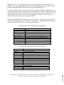
The BDM also utilizes a small ROM that contains the BDM firmware commands shown in Table
2. The BDM firmware commands can not be executed by the BDM circuitry so they have to be
executed by the CPU. This means that these commands can not be executed without preempting
the user program, which means they affect the real-time operation of the user program. For
example, notice that the commands used to access the registers require the CPU. This means
reading the register contents will require the user program to be preempted. On the other hand, a
read or write to memory can be done while the user program is running.
These commands are sent by a host connected to the BDM port, BKGD. The host is typically
made up of PC and a BDM pod, which translates the PC commands to BDM commands. Keep in
mind that the commands shown here are transparent to the user because development systems
designed for the BDM provide a more user-friendly interface. Typically, the user will enter DBug12 commands on a PC or select widgets in a graphical user interface. The host system will
then convert that request into the required BDM commands and send them to the MCU.
To use the BDM commands, the CPU must be placed under BDM control. To accomplish this,
there is a Special Single-Chip mode in addition to the Normal Single-Chip mode. In Special
Single-Chip mode, the CPU is placed under BDM control and the BDM firmware ROM is
available. There are also some subtle differences in MCU configuration between the two modes.
For example, the COP monitor resets are disabled in the Special Single-Chip mode.
During the debugging process, the MCU is reset in the Special Single-Chip mode. Once reset, the
CPU is placed under BDM control, which is waiting for a command to be sent by a host. The
host can send command sequences that load a program into RAM, program an on-chip
EEPROM, or execute a program. This mode is used to develop the program until it appears to be
operating to specification. At that point, the MCU is reset in Normal Single-Chip mode and the
transition to final product is complete. This BDM system combined with on-chip EEPROM
makes the transition from the debugging process to the final product very simple.
An Inexpensive BDM System 3,7
There are several BDM debugging systems available for the 68HC12 family. The debugging
system described here uses two Motorola M68EVB912B32 boards – one is used as the final
product (target) and the other is used as a BDM pod. It is a relatively inexpensive solution and
uses the same D-Bug12 command interface and evaluation boards that are commonly used in a
beginning course. Although this system uses the D-Bug12 interface, it is important to realize that
D-Bug12 is no longer resident on the target board. It runs on the POD board and uses the BDM
interface to communicate to the target. This has all of the advantages of using the BDM system
while using the familiar D-Bug12 command interface.
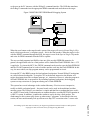
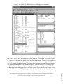
Figure 2 shows the hardware configuration for a system that uses two M68EVB912B32
evaluation boards. One is configured as a BDM pod and the other is configured as a target. The
POD is connected to a PC COM port and the target’s BDM connector. The POD runs D-Bug12
Page 6.751.5
Proceedings of the 2001 American Society for Engineering Education Annual Conference & Exposition
Copyright © 2001, American Society for Engineering Education