1
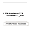
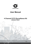
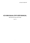
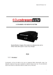
User Manual User Manual Contents Introduction ....................................................................................................................................................... 3 1. Overview ....................................................................................................................................................... 4 1.1 Range of Application ............................................................................................................................... 4 1.2 Product Description ................................................................................................................................. 4 1.3 Operation Environment ........................................................................................................................... 5 2. Device Connection ........................................................................................................................................ 5 3. Device Operation Instructions ....................................................................................................................... 6 3.1 Check Connection ................................................................................................................................... 6 3.2 Searching Device ..................................................................................................................................... 6 3.3 Installation of Controls and Login to System .......................................................................................... 8 3.3.1 Preview ............................................................................................................................................. 8 4. Parameter Setting......................................................................................................................................... 11 4.1 Display Configuration ........................................................................................................................... 11 4.2 Image Control ........................................................................................................................................ 12 4.3 Video Blocking...................................................................................................................................... 12 4.4 ROI (if applicable) ................................................................................................................................. 13 5. Network Parameters .................................................................................................................................... 14 5.1. Network Parameters ............................................................................................................................. 14 5.2 Bit stream setting ................................................................................................................................... 15 5.3 E-Mail Configuration ............................................................................................................................ 16 5.4 DDNS Configuration ............................................................................................................................. 17 5.5 IP Filtering ............................................................................................................................................. 18 5.6 RTSP ..................................................................................................................................................... 18 5.7 FTP ........................................................................................................................................................ 19 6. Alarm Parameter .......................................................................................................................................... 20 6.1 Mobile Detection ................................................................................................................................... 20 6.2 I/O Alarm (if applicable) ....................................................................................................................... 21 6.3 Lens Blocking........................................................................................................................................ 21 7. Device .......................................................................................................................................................... 22 1 User Manual 7.1 Audio ..................................................................................................................................................... 22 7.2 Logs ....................................................................................................................................................... 23 8. System Parameters....................................................................................................................................... 24 8.1 Basic Information .................................................................................................................................. 24 9. Advanced ..................................................................................................................................................... 26 9.1 System Update ....................................................................................................................................... 26 9.2 Default Parameters ................................................................................................................................ 26 9.3 System Maintenance .............................................................................................................................. 27 2 User Manual Introduction Thank you for using our network camera products, which are integrated and developed for network video monitoring, including Storage Network Bullet, Wireless Storage Network Bullet, IR Network Dome, IR Network Weather-Proof Cameras and High-Speed Network Ball. High-performance single SOC chips are used in media processor for audio/video acquisition, compression and transmission/transfer. Standard H.264 encoding algorithm is applied to ensure clear and smooth video representation and transfer performance. Embedded Web Server offers users access to real-time surveillance and remote control of front-end camera through IE browser. These network cameras are easy to install and operate, and applicable to large and medium-size enterprises, governmental projects, large mall, chain supermarkets, intelligent buildings, hotels, Hospitals and schools and other group customers, as well as to situations requiring remote network video transmission and monitoring. Instructions: For purpose of this manual, IP camera means network camera. Single click means a single click on the left mouse button. Double click means a double-click on the left mouse button. The default factory IP address for IP camera is 192.168.1.168. The default factory administrator user name for IP camera is admin (in lowercase), and the password is admin (in lowercase). The default Web port number is 80 and the default media port number is 9988. Statement: Some information contained in this manual may differ from the version which you are using. For any problem which you cannot solve with use of this manual, contact our technical support or dealer. This manual may be subject to any update from time to time without prior notice. 3 User Manual 1. Overview 1.1 Range of Application The network cameras with powerful image processing capacity may be applied at various public places such as mall, supermarket, school, factory and workshop, as well as in environments requiring HD video image such as bank and traffic control system, as shown below: Monitoring Center 1.2 Product Description An IP camera is a digital online surveillance camera integrated with embedded Web server and operating independently, giving user access to real-time monitoring through web browser or client software from any place across the world. IP camera is based on the latest Hisilicon solution, an integrated media processing platform for audio/video acquisition, compression and network transmission on a single board. It is in compliance with H.264/ H265 High Profile encoding standards. Any remote user can have access to real-time monitoring by entering the IP address or domain name of the IP camera in web browser. This network camera solution is applicable to family or office as well as a wide range of situations requiring remote network video monitoring and transmission. The IP camera products are easy to install and operate. The IP cameras can be managed by several users with authority of different levels. IP cameras allows mobile detection, and sends e-mail and snaps taken in case of emergency and store the image or video snapped in SD card for retrieval by user. 4 User Manual 1.3 Operation Environment Operating system: Windows 7/Windows 8/Windows 2008 (32/64-bit), Windows 2003/Windows XP/Windows 2000 (32-bit) CPU: Intel Core Duo II dual-core processor or higher Memory: 1G or more Video memory: 256M or more Display: 1024 ×768 or higher resolution IE: IE 6.0 or higher version 2. Device Connection IP camera can be connected by either of two means: 1. Connection to PC Connect IP camera to PC via straight-through network cable, with power input connected to a DC 12V adaptor, and set the IP addresses of the PC and IP camera in one network segment. The IP camera will communicate with PC within one minute after being powered on if the network operates normally. 2. Connection to router/switch This is more commonly used in connecting the IP camera to Internet, where the camera and PC are connected to LAN ports of a router/switch, with gateway of the camera set to the IP address of the router. 5 User Manual 3. Device Operation Instructions 3.1 Check Connection 1. 2. The default factory IP address for IP camera is 192.168.1.168 and the subnet mask is 255.255.255.0. Allocate to your computer an IP address in the same network segment as the IP camera, for example, 192.168.1.69, and a same subnet mask as that of the IP camera. Test whether the IP camera is connected properly and started normally by clicking on Start > Run and entering "cmd" and pressing ENTER, and entering "ping 192.168.1.168" in the command line window to Check whether the IP camera is accessible. If the PING command is executed successfully, it indicates that the IP camera operates normally and the network is connected properly. If the PING command fails, check IP address and gateway setting of the PC and connectivity of the network. 3.2 Searching Device Tips: IPC Device Search may be used for device searching across segments. Before running IPC Device Search, click on the local connection icon at the lower right corner of the desktop; 1. Add IP addresses of several network segments in TCP/IP setting for local connection (as shown below). By running the searching tool you can search any device with IP address in the same network segment. 6 User Manual Note: IPC Device Search uses multicast protocol for device searching across segments but any firewall forbids traffic of multicast data packets, so any firewall must be disabled in order that network the information on device can be acquired. Online device searching procedure 1. Run IPC Device Search by double clicking icon . It will search and display any online IPC and its IP address, port number, number of channels, device type and version, subnet mask, gateway, MAC address and connection pattern. 7 User Manual 3.3 Installation of Controls and Login to System Before using IE (Internet Explorer) browser to access the IP camera for the first time, related plug-in components must be installed by observing the following procedure: Access IP address of the IP camera to automatically load the controls from it. In a pop-up plug-in installation dialog box, choose an installation option to perform the installation process. IPC Plug-In for 2MP Series IPC Plug-In for 3MP/4MP Series 3.3.1 Preview Operate IE and enter the IP address of the camera (http://192.168.1.168) to open a login box as shown below: Login Interface for H.265 IP Cameras in 3.0MP/4.0MP Series Figure 1 8 User Manual In the login box you can choose a language for the IE client. Enter your user name (admin by default) and password (admin by default) and then press OK to open a preview frame as shown below: Some buttons in the preview frame are described below. : Color setting button, for setting of color, brightness, contrast, saturation and sharpness of the frame. : Access to device setting menu, for customized setting of various device parameters. : For setting of snap, video file type and storage path. : Help information (including current user, Web browser and plug-in versions), logout button, for returning to the login page. : Preview frame ratio adjustment, toggling between Original Ratio and Automatic Ratio. : Preview control buttons - Zoon-In/Out, Open Video, Snap and Sound On/Off, arranged from the left to the right. : Dynamic switching of bit stream for the preview frame. 9 User Manual Login Interface for H.264 IP Cameras in 1.3MP/2MP Series Figure 2 In this login page, you can choose preview bit stream, language for IE client and port number. Enter your user name (admin by default) and password (admin by default) and then press OK to open a preview frame as shown below: Some buttons in the preview frame are described below. : Access to device setting menu, for customized setting of various device parameters. : For setting of snap, video file type and storage path. : logout button, : : For returning to the login page. : Preview control buttons - Play, Stop, Full Screen, Snap, Start/Stop Recording, Enable/Disable Real-Time Talk. : Sound On/Off, Video Setting 10 User Manual Click Path Configuration button to pop up the following dialog box: In this dialog box you can set video storage location, paths for download of remote file and storage of image snaps, file type (RF by default, in H265 encoding) and video recording duration. 4. Parameter Setting 4.1 Display Configuration Click on Parameter Setting to open the page as below (preview setting page by default): Name of channel: name of the IP camera Display of channel: Choose to display or conceal it. Time display: Choose to display or conceal it. Blinking control: Choose 50Hz, 60Hz or disable it. Transparency: Choose transparency of display of name of channel and time on the preview frame (smaller value indicates higher transparency) OSD: the text in red color on the frame; you can locate display of the name of channel and time by dragging it in the preview frame. 11 User Manual 4.2 Image Control Click on Image Control in Display Configuration to open the following page: IR-Cut Model: Classified into GPIO Automatic, Colored, and Black-White models. Delay: IR-cut switching delay. Image Flip-Over: vertical or horizontal flip-over and rotation angle (0°, 90°, 180°, 270°) Image Control: backlight compensation, 3D noise reduction, WDR, automatic gain, shutter speed, exposure time and de-moist model. Note: Image rotation and de-moist are unavailable in IP camera of 2MP. 4.3 Video Blocking Click on Video Blocking in Display Configuration to open the following page: 12 User Manual Procedure of setting video blocking: 1. Check Enable Video Blocking 2. Press down and hold the left mouse button and drag out a area for video blocking (up to four areas at one time) 3. Click on Save to enable the video blocking area. Remove: After clicking Refresh, choose a blocked area by clicking it and then click Remove and click Save to remove it. 4.4 ROI (if applicable) Click on ROI in Display Configuration to open the following page: Procedure of setting ROI: 1. Choose an area of application 2. Press down and hold the left mouse button and drag out a ROI area (only one ROI can be set for each area) 3. Click on Save to apply the ROI area. Bit stream type: Choose bit stream effective for ROI among Main Bit Stream, Sub-Bit Stream and Cell Phone Stream. Area Numbering: Up to 8 ROI areas can be set in one bit stream. Enable ROI area: Enable or disable ROI area Area image quality: Set quality of the image in the area (relative quality, absolute quality) ROI level: Set ROI level in one bit stream; larger value indicates higher-quality image in ROI area (1~6 Levels) 13 User Manual Non-ROI frame rate: Set frame rate out of RIO area; smaller value indicates higher-quality image in ROI area. Range of frame rate is in relation to video standard and resolution. (Note: Different non-ROI frame rates may be allocated to different ROI areas, but the minimum value among them is used as the frame rate to be applied for the non-ROI area on the preview frame. ) 5. Network Parameters 5.1. Network Parameters Click on Network Parameters in Network Parameter Menu to open the following page: Networking mode: DHCP (Automatically Acquired), Manually Configured and PPPOE; the default is Manually Configured Media port: Media port for IPC Web port: Web port for IPC Cell phone port: Port for connection of cell phone client IP address: IP address of IPC Subnet mast: Subnet mast of IPC Default gateway: Default gateway of the device Preferred/Alternate DNS server: Set DNS server 14 User Manual UPNP: Enable or disable UPNP function for the device (enabled by default) Note: To enable UPNP, the media/web/cell phone port should be set to a value between 1024-65535; the media port is used for connection of proprietary cell phone client; cell phone port is used for connection of ASEE or ASEE+client. 5.2 Bit stream setting Click on Bit Stream Setting in Network Parameter Menu to open the following page: By default the available bit streams are: main bit stream, sub-bit stream and cell phone bit steam. You can set resolution, frame rate, video encoding, encoding level, audio, I frame interval, variable frame rate and bit stream size respectively for main bit stream, sub-bit stream and cell phone bit steam. Resolution: Set resolutions respectively for bit streams: The highest resolution for main bit stream is 2048×1536. The higher resolution for sub-bit stream is 704×480. The only resolution available for cell phone bit steam is 320×480. Note: The higher resolution for main bit stream of 3MP Series is 2048*1536 (frame rate of 30 fps). The higher resolution for main bit stream of 4MP Series is 2592*1520 (frame rate of 15 fps). The higher resolution for main bit stream of 2MP Series is 1920*1080 (frame rate of 30 fps). Frame rate: When refresh rate is 50Hz, the maximum available frame rate is 25 fps. When refresh rate is 60Hz, the maximum available frame rate is 30 fps. Video encoding: Set video encoding (H265/H264) for each bit stream. Audio: Enable audio for each bit stream. 15 User Manual I frame interval: Set I frame interval. Bitrate control: Set constant or variable bitrate for bit stream. Bit stream: Set bit stream value by choosing fixed value or customizing it. Note: Range of main bit stream is 256-8192. Range of sub-bit stream is 128-4096. Range of cell phone bit steam is 8-1536. Video encoding and encoding level are unavailable in setting page of IP camera of 2MP Series. 5.3 E-Mail Configuration Click on E-Mail Configuration in Network Parameter menu to open the following page: E-Mail Configuration: mail service setting - used with alarm function to upload images snapped to the mail server. Enable e-mail: Enable or disable e-mail function. Port: The default port number is 25 (mail serve port). SMTP server: Enter the address of mail server. Address of sender: Address of sending mailbox Password of sender: Password of sending mailbox Address of recipient: Address of receiving mailbox Time interval: Time interval for sending mail (1 minute, 3 minute, 5 minute, 10 minute) E-mail test: Click it to test whether the mailbox is configured properly by sending a test mail to the recipient's mailbox. 16 User Manual 5.4 DDNS Configuration Click on DDNS Configuration in Network Parameter menu to open the following page: DDNS configuration: Dynamic DNS configuration - used with server for access from an extranet. Enable DDNS: Enable or disable it. Address of server: Choose "3322". Name of host: Enter the name of active server User name: Name of the user Password: Password of the user 17 User Manual 5.5 IP Filtering Click on IP Filtering in Network Parameter menu to open the following page: Filtering mode: Three modes are available (Allow all IP connections, Allow all IP connections as set, Forbid IP connection as set). Add: Add any allowed or forbidden IP address Delete: Delete any IP address added previously 5.6 RTSP Click on RTSP in Network Parameter menu to open the following page: RTSP Enabling: Enable or disable RTSP. RTSP is enabled by default. After it is disabled, it will not be found with ONVIF. 18 User Manual RTSP Port: The default port number is 554, and can be changed to another value between 1024 and 65535. Modification to the parameter will restart the system. Operation Instructions: For IP cameras of 3MP/4MP Series: rtsp://IP:Port/ch00/A A:0 (main bit stream), 1(sub-bit stream), 2 (cell phone bit stream) For IP cameras of 2MP Series: rtsp://IP:Port /A A:0 (main bit stream), 1(sub-bit stream), 2 (cell phone bit stream) 5.7 FTP Click on FTP in Network Parameter menu to open the following page: FTP: FTP service setting - used with alarm function to upload images or videos snapped to the FTP server. FTP:Enable or disable it. User name:The user name for access to FTP service Password:The password for access to FTP service FTP Server: Enter the address of FTP server. Port:FTP service port number; the default number is 21. Transmit Image: Check it to transmit image 19 User Manual 6. Alarm Parameter 6.1 Mobile Detection Click on Mobile Detection in Alarm Parameter menu to open the following page: Procedure of setting Mobile Detection: 1. Check Enable Mobile Detection. 2. Press down and hold the left mouse button and drag out an area for mobile detection. 3. Set the sensitivity for mobile detection (ranging from 1 to 8; larger value indicates higher sensitivity). 4. Used with SMTP to enable mail delivery. 5. Click on Save to apply the settings. (Note: When any object moves within the target area, a letter "M" in green color will be displayed on the preview frame) 20 User Manual 6.2 I/O Alarm (if applicable) Click on I/O Alarm in Alarm Parameter menu to open the following page: I/O Alarm Input: Enable or disable I/O alarm. I/O Alarm Output Time: Set I/O alarm output time (10s, 20s, 40s, 60s) Recording Delay Time: After checking Enable Triggered Recording, you can set recording delay time (5S/10S/20S/30S) 6.3 Lens Blocking Click on Lens Blocking in Alarm Parameter menu to open the following page: Check Lens Blocking option (checked by default) to activate Security Level and Mail Linkage options. Security Level: Set security level for lens blocking (Level 1~8; larger value indicates higher security level) Mail Linkage: It is disabled by default. After being enabled, it may be used with SMTP to enable mail delivery. 21 User Manual 7. Device It includes Logs and Audio. Their interfaces and functions are described below. 7.1 Audio Click on Audio in Device menu to open the following page: Procedure of setting Audio: Check Open Audio option to access audio setting, and set audio input/output volume (ranging 0~10), and then click on Save to save the parameters set. (Note: For application of audio function, the audio option in Bit Stream Setting needs to be enabled) 22 User Manual 7.2 Logs Click on Logs in Device menu to open the following page: Log Type: Eight types of logs are available - system logs, network logs, parameter logs, alarm logs, user logs, recording logs, storage logs and all logs). Choose the starting and ending date/time for retrieval. Click on "Search" to retrieve and display related logs in the table below. Click on "Delete" to delete all device logs. Click on "Refresh" to refresh the logs selected. 23 User Manual 8. System Parameters System parameters include Basic Information, User Configuration and System Information. Their interfaces and functions are described below. 8.1 Basic Information Click on Basic Information in System Parameters menu to open the following page: The device time, system time, date format and time format contained in the basic information can be manually set and saved. Three automatic time correction functions are provided in this device. DST: Check Daylight Savings Time (DST) option to enable DST correction. The device will correct the time based on the time deviation as set. NTP: Check Enable NTP option, input the address of time server and choose a time zone and then save the setting. The system will correct time in accordance with the time server. Sync with PC Time: The device will use PC as a time server to correct time. 24 User Manual 8.2 User Configuration Click on User Configuration in System Parameters menu to open the following page: Here you can set user access authority and login password. 8.3 System Information Click on System Information in System Parameters menu to open the following page: Here some system information on the device will be displayed, including device type, MAC address and software version. 25 User Manual 9. Advanced It includes System Update, Default Parameters and System Maintenance. Their interfaces and functions are described below. 9.1 System Update Click on System Update in Advanced menu to open the following page: Update will be unavailable if the update files do not match the target device. 9.2 Default Parameters Click on Default Parameters in Advanced menu to open the following page: Check relevant options and click on Save to recover the default factory settings for the options as checked. 26 User Manual 9.3 System Maintenance Click on System Maintenance in Advanced menu to open the following page: Here you can set regular restart or manual restart of the device. 27 User Manual 28