1
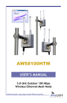
AW58100HTA, HTS
User’s Manual
D. Use a large Phillips head screwdriver to mount
your radio to Bracket Arm B using the four Radio
Mounting Screws. Use small washers and lock washers
if necessary. Make sure that the orientation arrow on
the back of the panel antenna faces upward so that
the drainage hole is at the bottom of the radio.
E. Assemble the cable gland on the end of your RJ45
Ethernet cable(not provided). Then connect the
cable to your radio’s Ethernet port, and fasten the
gland. The gland must be fully tightened to provide a
waterproof seal.
2. The AW58100HTS units have dual directional flat panel antennas. It is important that the
AW58100HTS antennas be pointed toward their Access Point AW58100HTA. Care should be taken to
align the AW58100HTS panel antenna to provide the best performance. The HTS antenna performs
best when the panel’s face is aligned toward its partner. By browsing to the Access Point radio, you
can see a graphical representation of signal strength received from each linked Subscriber Unit. Click
the row in the table to display the graph for that particular unit. This information can be used to
facilitate the aiming process.
3. Power is provided to the units by means of their Ethernet cables, allowing the power supplies to
be located at convenient locations. The included power-over-Ethernet injectors (POE) provide the
means for adding DC power to unused wires in the cable. Each radio is provided with a cable clamping
device that allows an RJ45 plug on the cable to pass through and can be tightened down around the
cable to provide a weatherproof seal.
Technical Support (650) 384-0000
PAGE 10
www.avalanwireless.com