1
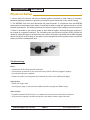
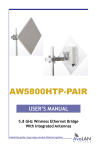
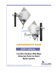
AW58300HTP-PAIR
USER’S MANUAL
5.8 GHz Outdoor 300 Mbps
Ethernet Point-to-Point
Radio System
Industrial-grade, long-range wireless Ethernet systems
AvaLAN
W
I
R
E
L
E
S
S
AW58300HTP-PAIR
User’s Manual
The AW58300HTA is a radio with dual omnidirectional antennas. It serves as an Access Point (master) in
a point-to-multipoint network. The AW58300HTS is a radio with a dual flat panel high gain directional
antenna. Multiple AW58300HTS radios can serve as a Subscriber Units (clients) in conjunction with an
AW58300HTA.
The AW58300HTP-PAIR includes:
(2) AW58300HTS Bridge Radios
(2) Heavy Duty Pole-mount Bracket
(2) Power Over Ethernet Injector
(2) 18 VDC Power Supplies
Table of Contents
Quick Start Guide . . . . . . . . . . . . . . . . . . . . . . . . . . . . . . . . . . .
LED Status Guide . . . . . . . . . . . . . . . . . . . . . . . . . . . . . . . . . . .
Digital Configuration . . . . . . . . . . . . . . . . . . . . . . . . . . . . . . . . . . . . .
Connecting To The Radio . . . . . . . . . . . . . . . . . . . . . . . . . . . . . . .
Changing the Configuration - Step By Step . . . . . . . . . . . . . . .
Viewing Status Information . . . . . . . . . . . . . . . . . . . . . . . . . . . . . .
Physical Setup . . . . . . . . . . . . . . . . . . . . . . . . . . . . . . . . . .
Technical Specifications . . . . . . . . . . . . . . . . . . . . . . . . . . . . . . .
Frequency Channels . . . . . . . . . . . . . . . . . . . . . . . . . . . . . . . . . . . . .
Warranty and FCC Information . . . . . . . . . . . . . . . . . . . . . . . . . . . .
3
4
5
5
6
8
9
10
11
11
If you have any questions when configuring your AvaLAN system, the best place to get answers is
to visit www.avalanwireless.com. You will also find the latest updates there. If more assistance is
needed, send email to [email protected].
To speak to a live technician, please call technical support at the number below during normal
business hours.
© by AvaLAN Wireless Systems Inc. All rights reserved.
Revision 3.5.2014
125A Castle Drive
Madison, AL 35758
Phone: (650) 384-0000
Fax: (650) 249-3591
Technical Support (650) 384-0000
PAGE 2
www.avalanwireless.com
AW58300HTP-PAIR
User’s Manual
Quick Start Guide
Step 1. Radios are Preconfigured out of the Box
Step 2. Mount Radios
Step 3. Align Radios
Step 4. Attach Cables
System Default:
IP Address: 192.168.88.12 (Bridge A Unit)
192.168.88.10 (Bridge B Unit)
Username: admin
Password: password
Best Practices:
Tools Needed:
1. Ensure clear visual path between radios before deployment
- ½ inch wrench
2. Test on bench before deployment
- Large Phillips head screwdriver
3. Networking Cable:
- Small flat screwdriver
- CAT 6 Shielded Outdoor Grade
- For AW58300HTP - maximum length 300 ft/100 meters
Point-to-Point
AW58300HTP
Up to 30 miles Line-of-Sight
Supported
Networking Cable*
POE
POE
*Networking cable not provided
Technical Support (650) 384-0000
PAGE 3
www.avalanwireless.com
AW58300HTP-PAIR
User’s Manual
LED Status Information
Bridge A LED Guide
Ethernet
Wireless
Status
The wireless status light blinks slowly when the product is powered
and is lit solid when it has a successful wireless connection.
Rx
This light will blink when receiving data
Tx
This light will blink when transmitting data
Bridge B LED Guide
Status
The wireless status light blinks slowly when the product is powered
and is lit solid when it has a successful wireless connection.
Wireless
The wireless activity light blinks when receiving data.
Ethernet
The Ethernet activity light blinks when receiving data.
Technical Support (650) 384-0000
PAGE 4
www.avalanwireless.com
AW58300HTP-PAIR
User’s Manual
Digital Configuration
Connecting to the radio
1. Digital configuration is done by means of the radio’s built in browser interface. The unit should be
powered on and connected at least temporarily to a network containing a computer that can run a
conventional web browser.
2. Using your web browser, connect to the radio as described in the Quick Start Guide found earlier
in this manual.
3. The initial page after a successful login is “Quick Set.” The content of this page is somewhat
different for the AW58300HTP Bridge A and Bridge B.
4. Each page provides a menu on the left to navigate from section to section. The menu looks like this
when its sections are expanded:
Beware that certain actions may cause the web page to freeze. In most cases, this is because you are
viewing a browser-cached version of the page and not the live one from the radio. Clear your browser
cache and/or logout and log back in to recover. You are cautioned not to use the “back” button on
your browser to attempt to move back to earlier pages. If you do, you will be logged out and will
need to login again.
In the upper right of the page is a label that tells you the version of the web interface. If the
version number is not the same as shown below, you might want to visit www.avalanwireless.com
(the Downloads page under the Support menu) to see if a newer version of this manual exists before
proceeding further.
Technical Support (650) 384-0000
PAGE 5
www.avalanwireless.com
AW58300HTP-PAIR
User’s Manual
Changing The Configuration - Step by Step
Please be aware that if you change the IP Address or User Password and forget their new values, you
have locked yourself out of the browser interface. The AW58300 runs self-diagnostics at boot-up and
will auto-correct most system configuration errors. Prior to calling technical support, it is recommended to power cycle the radio and confirm that the problem remains.
In the event of a lost IP address, reboot the AW58300 to create a temporary IP address of 192.168.88.88
that can be used to access the radio to reset the user-defined IP address. This IP address expires after
3 minutes from reboot. In the event of a lost password, please contact AvaLAN technical support for
assistance.
If you are changing parameters over the RF link (we do not recommend this), be sure to make the remote changes first because the link will be broken if the network name or Security Keys do not agree.
1. Setting the IP Address and Subnet Mask, Gateway and Device Name:
•In the upper right area of the Quick Set page are the data entry boxes for these parameters.
They contain the current values.
•A special notation is used for the IP Address and Subnet Mask: Use /x at the end of the
IP Address to specify the subnet mask: /8 for 255.0.0.0, /16 for 255.255.0.0 and /24 for
255.255.255.0. Enter a new IP Address and subnet making sure you will be able to browse to
the new address with your computer. Also, make sure that the new IP address is unique on your
LAN.
•The Gateway address should be specified if it is necessary to communicate with the radio
through the Gateway. Your system administrator should have this value.
•The Device Name is an arbitrary string and simply allows you to attach a human-friendly name
to this specific radio.
•Click “Apply Configuration” when you have entered new values. Nothing appears to happen, but
you have been disconnected and will need to browse to the new IP Address to login again.
Technical Support (650) 384-0000
PAGE 6
www.avalanwireless.com
AW58300HTP-PAIR
User’s Manual
2. Setting the User Password:
•On the Main Menu at the left side of the browser window, click “System”, then click
“Password.”
•Enter the old password and the new password twice in the boxes indicated.
•Click the “Change” button.
•Log out and log back in to test.
3. Setting the Frequency, Network name and Encryption Key:
•To set the Frequency, log in to the Bridge A and on the quick start page a selection can be made.
•The Network name is an arbitrary character string that must be set alike in all linked radios.
•The Encryption Key is also an arbitrary character string that is used to generate the 128 bit key.
Technical Support (650) 384-0000
PAGE 7
www.avalanwireless.com
AW58300HTP-PAIR
User’s Manual
Viewing Status Information
After configuring your AvaLAN radios and establishing links among them, you can use the browser
interface to view status and troubleshooting Information. The initial “Quick Set” page will show
whether the wireless link is operating and the current signal strength. For more comprehensive information, choose “Wireless” from the Main Menu at the left side of the window. The “Wireless” page
leads to most of the useful status information.
The table on the Interfaces tab provides a list of the interface processes running in this radio. If it is
Bridge B, there will be only one, “Wireless_Radio.” If it is Bridge A, there will also be a WDS process
running. These rows summarize the configuration details and current running status of the radio.
Technical Support (650) 384-0000
PAGE 8
www.avalanwireless.com
AW58300HTP-PAIR
User’s Manual
Physical Setup
1. Mount each unit securely using the mounting brackets provided or other means as necessary.
Maximize lightning resistance by providing a strong DC ground connection to the metal housing.
2. The AW58300 units have dual directional flat panel antennas. It is important that the AW58300
antennas be pointed toward each other. Care should be taken to align the panel antenna to provide
the best performance. The antenna performs best when the panel’s face is aligned toward its partner.
3. Power is provided to the units by means of their Ethernet cables, allowing the power supplies to
be located at convenient locations. The included power-over-Ethernet injectors (POE) provide the
means for adding DC power to unused wires in the cable. Each radio is provided with a cable clamping
device that allows an RJ45 plug on the cable to pass through and can be tightened down around the
cable to provide a weatherproof seal.
Troubleshooting:
Power:
- Check that the POE cabling matches illustration
- Check network connection on your switch and verify all RJ45 cables are plugged in properly
- Only use the POE injector supplied
- Ensure the 110VAC is providing clean and consistent AC power to the 18VDC power supply
Signal Quality:
- Ensure line of sight (LOS)
- Check signal strength in web interface (-40dB is excellent strength and –80dB is weak)
Web Interface:
- Plug RJ45 male side of POE directly in to computer and verify network status shows connected
- Verify the local computer’s network settings are in the same IP subnet range as the radio
Technical Support (650) 384-0000
PAGE 9
www.avalanwireless.com
AW58300HTP-PAIR
User’s Manual
Technical specifications
CHARACTERISTIC
SPECIFICATION/DESCRIPTION
RF transmission rate
300 Mbps
Ethernet data rate
Up to 180 Mbps
Output power AW58300HTP
200 watts EIRP with 23 dBi directional antenna
Receiver Sensitivity
-115 dBm
Frequency Range
5.725 - 5.850 GHz
Channel Bandwidth
40 MHz
RF channels
2 Non-Overlapping with 40 MHz Channel Bandwidth
Modulation
OFDM (BPSK, QPSK, 16-QAM, 64-QAM)
Range
Line-of-sight range up to 30 miles
Browser Management Tools
QoS Statistics, Network Settings, Channel Selection
Data Security
AES 128-bit Encryption
Operating Environment
-40ºC to +70ºC, sealed for outdoor operation: die cast aluminum package with rubber gasket seals
Mounting
Heavy Duty Pole-Mount Bracket included
Connector
10/100/1000 Ethernet RJ-45 with weatherproof sealing gland
Power System
Power Over Ethernet 18 VDC Injectors included: 100-240 VAC 50/60Hz
primary source
AW58300HTP Antenna
Integrated 23 dBi flat panel, 13” square, 10° Beamwidth
AW58300HTP Size
13” by 13” by 3.25”, not including pole-mount bracket, weight 7 lbs
Warranty
1 Year Parts & Labor, XTRa-Care extended warranty available
Certification
FCC, IC
Technical Support (650) 384-0000
PAGE 10
www.avalanwireless.com
AW58300HTP-PAIR
User’s Manual
Frequency Channels
Frequency
MHz
5745
5750
5755
5760
5765
5770
5775
5780
5785
5790
5795
5800
5805
5810
5815
5820
5825
Non-overlapping
40 MHz Bandwidth
X
Default
Limited Warranty
This product is warranted to the original purchaser for normal use for a period of 360 days from the
date of purchase. If a defect covered under this warranty occurs, AvaLAN will repair or replace the
defective part, at its option, at no cost. This warranty does not cover defects resulting from misuse
or modification of the product.
If you wish, you may purchase extended warranty for this product. AvaLAN’s XTRa-Care Extended
Warranty provides a two-year extension plus free overnight (Continental USA only) product replacement. Visit our website for more details.
Regulatory Compliance
Technical Support (650) 384-0000
PAGE 11
www.avalanwireless.com