1
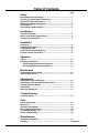
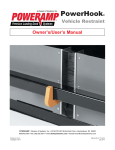
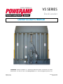
VS SERIES
Dock Leveler
Owner’s/User’s Manual
POWERAMP • Division of Systems, Inc. • W194 N11481 McCormick Drive • Germantown, WI 53022
800.643.5424 • fax: 262.257.7399 • www.docksystemsinc.com • [email protected]
Printed in U.S.A.
Copyright © 2008
Manual No. 4111-0008
September 2012
Table of Contents
Page
Safety
Recognize Safety Information .............................................................
General Operational Safety Precautions ............................................
Operational Safety Precautions...........................................................
Maintenance Safety Precautions .........................................................
Safety Decal’s ........................................................................................
Owners/Users Responsibility ..............................................................
1
1
2
4
5
6
Introduction
General Information .............................................................................. 6
Dock Leveler Stock Specifications ..................................................... 6
Component Identification ..................................................................... 7
Installation
Prepare Pit ............................................................................................. 8
Prepare Dock Leveler .......................................................................... 9
Install Dock Leveler ............................................................................ 10
Install Control Panel and Wiring ....................................................... 13
Put New Leveler Into Service............................................................. 15
Operation
Theory ..................................................................................................
Operating Instructions .......................................................................
Ramp Loading/Unloading Instructions .......................................
End Loading/Unloading Instructions...........................................
16
22
18
19
Maintenance
Service Dock Leveler Safely .............................................................. 20
Periodic Maintenance ......................................................................... 21
Adjustments
Adjust Main Pressure Relief SC ........................................................
Adjust Main Pressure relied Remote System ..................................
Purging Hydraulic System .................................................................
Limit Switch .........................................................................................
Rode Eye Adjustment .........................................................................
23
24
14
25
15
Troubleshooting
Troubleshooting .................................................................................. 27
Parts
Frame and Platform ............................................................................
Misc Parts ............................................................................................
Hydraulic Valve Blocks ......................................................................
Hoist Cylinder Repair Parts ...............................................................
Lip Cylinder Repair Parts ..................................................................
Power Pack Assembly .......................................................................
35
32
42
48
49
50
Miscellaneous
Customer Information ........................................................................ 52
Warranty............................................................................................... Back Cover
SAFETY
Recognize Safety Information
General Operational Safety
Precautions
Safety-Alert Symbol
The Safety-Alert Symbol identifies important safety
messages on equipment, safety signs, in manuals,
or elsewhere. When you see this symbol, be alert
to the possibility of personal injury or death. Follow
the instructions in the safety message.
Read and understand the operating instructions and
become thoroughly familiar with the equipment and
its controls before operating the dock leveler.
Never operate a dock leveler while a safety device or
guard is removed or disconnected.
The use of the word DANGER signifies the
presence of an extreme hazard or unsafe practice
which will most likely result in severe injury or
death.
Never remove DANGER, WARNING, or CAUTION
signs or Decal’s on the equipment unless replacing
them.
The use of the word WARNING signifies the
presence of a serious hazard or unsafe practice
which may result in serious injury or death.
The use of the word CAUTION signifies possible
hazard or unsafe practice which could result in
personal injury.
IMPORTANT
The use of the word IMPORTANT is to draw
attention to a procedure that needs to be followed
to prevent machine damage.
Do not start the equipment until all unauthorized
personnel in the area have been warned and have
moved outside the operating zone.
Remove any tools or foreign objects from the
operating zone before starting.
Keep the operating zone free of obstacles that could
cause a person to trip or fall.
4111-0008 — Sept 2012
1
SAFETY
Operational Safety Precautions
Learn the safe way to operate this equipment. Read and understand the manufacturer’s
instructions. If you have any questions, ask your supervisor.
Stay clear of dock leveling device when freight
carrier is entering or leaving area.
Chock/restrain all freight carriers. Never remove
the wheel chocks until loading or unloading
is finished and truck driver has been given
permission to drive away.
Do not move or use the dock leveling device if
anyone is under or in front of it.
Do not use a broken or damage dock leveling
device. Make sure proper service and
maintenance procedures have been performed
before using.
Keep hands and feet clear of pinch points. Avoid
putting any part of your body near moving parts.
Make sure lip overlaps onto trailer at least 4 in.
(102 mm).
Keep a safe distance from both side edges.
2
4111-0008 — Sept 2012
SAFETY
Do not use dock leveling device if freight carrier is
too high or too low.
Do not overload the dock leveling device.
Do not operate any equipment while under the
influence of alcohol or drugs.
Do not leave equipment or material unattended on
dock leveling device.
4111-0008 — Sept 2012
3
SAFETY
Maintenance Safety Precautions
ALWAYS stand clear of dock leveler and lip when
working in front of the dock leveler. Failure to do
this may result in serious personal injury or death.
ALWAYS disconnect electrical power source and
ground wire before welding on dock leveler.
Hydraulic and electrical power must be OFF when
servicing the equipment. For maximum protection,
use an OSHA approved locking device to lock
out all power sources. Only the person servicing
the equipment should have the key to unlock the
device.
DO NOT ground welding equipment to any
hydraulic or electrical components of the dock
leveler. Always ground to the dock leveler frame.
Failure to follow these instructions may result in
damage to dock leveler and/or serious personal
injury or death.
DO NOT grind or weld if hydraulic fluid or other
flammable liquid is present on the surface to be
ground or welded.
DO NOT grind or weld if uncontained hydraulic
fluid or other flammable liquid is present. Stray
sparks can ignite spills or leaks near the work area.
Always clean up the oil leaks and spills before
proceeding with grinding or welding.
Always keep a fire extinguisher of the proper type
nearby when grinding or welding.
Failure to follow these instructions may result in
serious personal injury or death.
Always post safety warnings and barricade the
work area at dock level and ground level to prevent
unauthorized use of the unit before maintenance is
complete.
The storage maintenance props (2) must be in the
“Maintenance” position when working under the
dock leveler and the storage prop must have a
grade 5 or better in the locking hole. For maximum
protection, use an OSHA approved locking device
to lock out the main power supply. Only the person
servicing the equipment should have the key to
unlock the device.
4
4111-0008 — Sept 2012
SAFETY
Safety Decal’s
4.00"
! DANGER
! DANGER
CRUSH HAZARD
DO NOT WORK UNDER DOCK LEVELER unless all
maintenance props have been properly positioned.
Side maintenance props must be positioned as shown
in figure “A” below. Prop locking pin must be positioned
as shown in figure “B” below. Refer to owner’s/user’s
manual for proper procedure. Failure to do so will
result in death or serious injury.
Storage
Position
6.25"
FIG.“A”
CRUSH HAZARD
DO NOT ENTER PIT unless dock
leveler is safely supported by
maintenance prop. Place barriers on
drive way and dock floor to indicate
service work being performed. Refer to
owner’s/user’s manual for proper
maintenance procedures. Failure to
comply will result in death or serious
injury.
FIG.“B”
Maintenance Position
Safety
Control Box Size:
Decal
4 x 6.25
Decal
onSize:
Leveler
Frame
File Name: 1751.0230 REV C
Control
Boxon
Size:
Safety
Decal
Rear Platform
Decal Size: 4 x 6
File Name: 1751-0130 Rev A
! DANGER
! DANGER
CRUSH HAZARD
DO NOT REMOVE hydraulic cylinder until leveler is
safely supported by maintenance prop. Refer to
owner’s/user’s manual for proper maintenance
procedure. Failure to comply will result in death or
serious injury.
If for any reason, the platform is raised by
means other than the hydraulic system, i.e.
Fork truck or crane, a hazardous condition may
exist, because the main hoist cylinder will have
air on the load bearing end. The cylinder will
not support the platform which can fall rapidly,
potentially causing injuries to anyone under the
platform. Be sure the leveler is restrained per
instructions in the owner’s/user’s manual. When
repairs/service is complete unit must be
operated in the “raised” direction only until
visible movement of platform indicates cylinder
is full. If alternate lifting means are still
available, use to return platform to original
lowered position and then raise unit
hydraulically.
Safety Decal on Platform Cylinder
Control Box Size:
Decal Size: 4 x 2
File Name: 1751-0138 Rev A
4111-0008 — Sept 2012
Safety Decal on Rear Platform
5
OWNER’S/USER’S RESPONSIBILITIES
1. The owner/ user should recognize the inherent dangers of the interface between the
loading dock and the transportation vehicle. The owner/ user should, therefore, train and
instruct all operators in the safe operation and use of the loading dock equipment in
accordance with manufacturer’s recommendations and industry standards. Before
operation of the equipment, all operators shall read, understand and be familiar with all
functions of equipment as described in the owner’s/user’s manual.
2. The manufacturer shall provide to the initial purchaser all necessary information with
regards to: Safety Information, Operation, Installation and Safety Precautions,
Recommended Initial and Periodic Inspections Procedures, Planned Maintenance
Schedule, Product Specifications, Troubleshooting Guide, Parts Break Down, Warranty
Information and Manufacturers Contact Information. The owner/ user shall be responsible
to verify that this information is available and received as well as proper instructions,
training and familiarity of the equipment for all operators has been completed. Owner’s/
User’s shall actively maintain, update and re train all operators on safe working habits and
operations of the equipment.
3. It is recommended when the transportation vehicle is positioned correctly in the dock
opening and in contact with both bumpers, there shall be a minimum of 4.00 inches
(100mm) overlap of the leveling device and the transportation vehicle at all times during
the loading and unloading process.
4. Name plates, placards, decals, instructions and posted warnings shall not be obscured
from the view of the operator or maintenance personnel for whom such warnings are
intended for. Contact manufacturer for any replacements.
5. Manufacturer’s recommended periodic maintenance and inspection procedures in effect at
the date of shipment shall be followed at all times. Written documentation of maintenance,
replacement parts or damage should be retained. In the event of damage notification to
the manufacturer is requested.
6. Any modifications or alterations of loading dock equipment shall only be done with prior
written approval from the original equipment manufacturer.
7. When industrial moving devices are being used in the loading or unloading of product
from the transportation vehicle, this vehicle shall have the brakes and wheel chocks
applied appropriately or all other positive restraining device shall be fully utilized.
8. Loading dock safety equipment should never be used outside of its intended use, range,
or capacity. Please consult the manufacturer if you have any questions as to the use,
range or capacity of the equipment.
9. When selecting loading dock safety equipment, it is important to consider not only present
requirements but also future plans and any possible adverse conditions, environments or
use.
6
4111-0008 — Sept 2012
INTRODUCTION
General Information
Dock Leveler Stock Specifications
Models
VS-65
VS-66
VS-68
VS-655
VS-656
VS-658
VS-75
VS-76
VS-78
Nominal Size W x L
6’ x 5’
6’ x 6’
6’ x 8’
6’6” x 5’
6’6” x 6’
6’6” x 8’
7’ x 5’
7’ x 6’
7’ x 8’
VS dock levelers are available in the following sizes,
weight capacities, and options:
Congratulations on your choice of a Poweramp
Vertical Storing dock leveler. This manual covers the
VS (Vertical Storing) series hydraulic dock leveler.
Designed by Poweramp to be a marvel of simplicity
and efficiency, your dock leveler, when properly
installed, will provide many years of troublefree performance with an absolute minimum of
maintenance. Its revolutionary hydraulic system
efficiently controls and operates every function. To
obtain maximum performance and longest possible
use, a simple program of preventive maintenance is
recommended.
Width: VS
6 ft (1828.8 mm)
6-1/2 ft (1981.2 mm)
7 ft (2133.6 mm)
Length
5 ft (1524 mm)
6 ft (1828.8 mm)
8 ft (2438 mm)
Capacity (CIR*)
40,000 lb (18 144 kg)
45,000 lb (20 412 kg)
50,000 lb (22 680 kg
* CIR (Comparative Industry Rating)
Call Poweramp to discuss available powerpack
mounting configurations, voltages, phases and
options to meet your specific needs.
The VS series dock leveler comes equipped with an
electrical control panel, which allows push button
operation of the dock leveler functions. Each VS dock
leveler unit and control panel has been factory
prewired and tested to ensure satisfactory operation.
To illustrate which connections are to be made
in the field at installation, electrical drawings are
included with each order or by contacting Poweramp
Technical Services.
Once again, thank you and congratulations on your
purchase of a Poweramp hydraulic dock leveler.
4111-0008 — Sept 2012
7
INTRODUCTION
Component Identification
A
B
C
D
E
K
F
G
H
I
G
J
A.
B.
C.
D.
E.
F.
Lip
Deck
Lip Cylinder
Flow Control Valve
Hoist Cylinder*
Storage Prop Yoke
G.
H.
I.
J.
K.
Trombetta Valve-Prop Kicker (Behind Prop Assy)
Storage Prop Assembly with Lock-Out Pin included (F)
Hinge Pin
Stored Limit Switch
Maintenance Props
* Some models are equipped with multiple hoist cylinders.
*Powerpack may be mounted on underside of leveler or remotely.
8
4111-0008 — Sept 2012
INTRODUCTION
This page was intentional left blank
4111-0008 — Sept 2012
9
INSTALLATION
Prepare Pit
A
B
C
D
C
A
B
A—Distance (Pit Width)
(Front and Rear)
B— Distance (Dock Floor-to-Pit
C— Distance (Pit Length)
Floor) (All Four Corners) 1/2”
(Both Sides of Pit)
Taper Rear to Front
Post safety warnings and barricade the work
area at dock level and ground level to prevent
unauthorized use of the dock leveler before
installation has been completed.
Failure to follow the installation instructions can
result in damage to dock leveler, the facilities, and/
or serious personal injury or death.
Only trained installation professionals with the
proper equipment should install this product.
Before lowering the dock leveler into the pit, the
following must be performed:
1. Remove all debris from the pit and sweep the pit
clean.
2. Check the entire dock leveler pit for proper
construction according to approved/certified
pit drawings. Make sure pit is square, has the
proper depth and taper by making the following
measurements:
10
D— Distance (Pit Corner-to-Corner) (Top,
Bottom, and Both Sides)
• Measure pit width distance (A) at both front and
rear of pit.
• Measure dock floor-to-pit floor distance (B) on
both sides of the rear embed channel and at
front if applicable.
• Measure pit floor taper, rear to front cannot
exceed 1/2” total taper.
• Measure pit length distance (C) at both sides.
• Measure corner-to-corner (cris-cross) distance
(D) at both sides. Take measurements at dock
floor level and at pit floor level.
NOTE” If any measurement are off by more than
1/8 in. (3.18 mm) in depth, width and
squareness 1/4 in + 0 in (6.32mm) contact
Poweramp Technical Services before
proceeding.
3. Make sure the field junction box for the dock
leveler (E) and floor embed plate (F) is at the
correct location per pit diagrams.
4111-0008 — Sept 2012
INSTALLATION
Prepare Dock Leveler
A
B
A— Lifting Bracket
The dock leveler is heavy. Use a lifting device and
chains with the appropriate lifting capacity and
reach.
B — Maintenance Props
Poweramp dock levelers are designed with
installation in mind. Each unit is shipped with lifting
bracket(s) (A) fastened to the platform.
IMPORTANT
Always use the lifting brackets provided with the
unit whenever lowering or lifting a dock leveler into
or out of a pit.
Failure to follow these instructions may result in
damage to dock leveler and/or serious personal
injury or death.
4111-0008 — Sept 2012
DO NOT remove the Maintenance Props at this
time. They should be rotated to the lowered
position during installation. They will keep the
leveler in the upright position, once the hinge
pins are installed, until the storage prop and hoist
cylinder are installed and the leveler is ready for
testing.
11
INSTALLATION
IMPORTANT
Installation of VS levelers from inside is
recommended due to combined height of leveler
and proper lifting equipment may be greater than
outside door height.
1. Remove any control panel, bumpers or pelletizing
that may be banded to the dock leveler. Do not
remove banding on hoist cylinder or storage prop
at this time.
2. Make sure the mounting hardware of lifting
bracket(s) (A) is snug. The brackets should pivot
relatively freely on the mounting cap screw.
DO NOT over tighten.
3. Attach lifting chain to lifting bracket(s) (A) and to
a lifting device (i.e., hoist or fork truck) having the
appropriate lifting capacity and reach.
A
NOTE: Overall length of lifting chain and bracket
(A) must be kept to a minimum to prevent
interference between the lifting equipment
and and the building ceiling or door as the
dock leveler is lowered into the pit.
Maintenance props in lowered location during installation and service.
12
4111-0008 — Sept 2012
INSTALLATION
Install Dock Leveler
Shim
Stacking Methods
E
F
G
H
I
B
C
IMPORTANT
The minimum size of the shim that contacts the
leveler frame (i.e., the top shim of each shim stack)
must be at least 4-1/2 x 4-1/2 in. (114.3 x 114.3
mm) to support the full width of the hoist cylinder /
storage prop weldment.
Use the thickest shim stock possible for stability
and weld penetration purposes. DO NOT use
multiple layers of 1/8 in. (3.18 mm) or thinner shim
stock.
D
4. Before installing the leveler the Imbed channel
must be shimmed and welded to the Imbed on the
pit floor.
A— Distance (Leveler Frame
Height)
B— Shim Location (Under
Maintenance Prop)
(Standard Dock Leveler
Only)
C— Dock Floor
D— Rear Imbed Frame
E— Imbed Frame
(Maintenance Prop)
4111-0008 — Sept 2012
B
C
A
F— Pyramid (Preferred)
G— Stepped (Acceptable)
H— Offset (Not Acceptable)
I — Straight (Not Acceptable)
E
13
INSTALLATION
The dock leveler is heavy. Use chains and a
lifting device with the appropriate lifting capacity
and reach. Failure to do so may result in damage
to dock leveler and/or serious personal injury or
death.
E
B
C
C
F
A
A— Rear Imbed
B— Dock Leveler
D
Bottle Jack
C— Maintenance Props
D— Hinge Pins
5. Lube the three rear hinge pins using grease Install
the three pins in the rear imbed only through out
the first hinge tube.
E— lifting Lug
F— Storage Prop
7. Once the three hinge pins are installed Install the
Storage prop. Install latch pin
8. Make all hydraulic connections.
6. lower the Vertical leveler down centering the
leveler’s three hinge pins with the imbeds three
pins.
• Insert the pins. Start with on outside first second
install the center pin and than the last out side
hinge pin.
9. Make all electrical connection.
Note: Do not connect hoist cylinder at this time.
Systems must be bleed before connected see
page 16
• Optional use: Us a bottle jack to align the rear of
the dock leveler to the imbed channel.
14
4111-0008 — Sept 2012
INSTALLATION
Install Control Panel and Wiring
A
The electrical power must be OFF prior to electrical
installation. For maximum protection, use an OSHA
approved locking device to lock out all power
sources. Only the person installing the equipment
should have the key to unlock the power source.
B
C
Failure to follow these instructions may result in
serious personal injury or death.
DO NOT make any final electrical connections until
all welding has been completed. Failure to do this
may result in serious personal injury or death.
All electrical work — including the installation of
the disconnect panel, control panel, and final
connections to the pit junction box — must be
performed by a certified electrician and conform to
all local and applicable national codes.
1. Mount the push button control panel (B) so bottom
of control panel-to-dock floor distance (C) is 48 in.
(1219.2 mm).
2. Install electrical disconnect panel (A) if not already
installed.
3. Install and connect the control wiring.
4. Connect the dock leveler power cable to the field
wires in the pit junction box. Refer to the electrical
drawings supplied with the dock leveler.
4111-0008 — Sept 2012
A— Disconnect Panel (provided by others)
B— Control Panel
C— Distance, 48 in. (14 630 mm)
5. Lower dock leveler check to make sure the
leveler goes into float mode (about 15” above
dock floor) allow to dock to float to full below
position. Make sure the dock makes contact with
pit floor. Push and hold the RAISE button until
the leveler turns off and the Blue stored light
comes on.
6
Check the lip operation: Lower dock leveler
check to make sure the leveler goes into float
mode (about 15” above dock floor) allow to dock
to float to below dock. Push and hold the RAISE
button until the leveler turns off and the Blue
stored light comes on.
15
INSTALLATION
Purging air from the VS hydraulic system.
DO NOT grind or weld if hydraulic fluid or other
flammable liquid is present on the surface to be
ground or welded.
DO NOT grind or weld if uncontained hydraulic
fluid or other flammable liquid is present. Stray
sparks can ignite spills or leaks near the work area.
Always clean up the oil leaks and spills before
proceeding with grinding or welding.
Always keep a fire extinguisher of the proper type
nearby when grinding or welding.
Failure to follow these instructions may result in
serious personal injury or death.
IMPORTANT
DO NOT connect the dock leveler electrical wiring
and ground connections until all welding has been
completed.
DO NOT ground welding equipment to any
hydraulic or electrical components of the dock
leveler. Always ground welding equipment to the
dock leveler frame, NEVER to the platform.
Failure to follow these instructions may damage the
motor, hoist cylinder, wiring, and/or control panel.
1. Begin by supporting the leveler in the stored
position with the storage prop and maintenance
props. Lock out the storage prop with the locking
bolt.
2. Lock-out and tag-out the leveler.
3. Disconnect the lower hoist cylinder mounting pin.
4. Remove one of two screws holding the stored
limit switch. Swivel stored limit switch away from
storage prop.
SEE PAGE 28
5. Open down speed flow control valve (counter
clockwise). Down speed control valve is located
on hoist cylinder
SEE PAGE 28
6. Restore power to the leveler. Confirm the blue
stored indicator light is no longer illuminated.
7. Cycle the hoist cylinder up and down at least 6
times using the leveler’s own hydraulic power.
8. Connect the hoist cylinder to the base of the
Imbed is channel.
9. Adjust down speed flow control to factory
settings. The settings are 1-1/2 turns out from
fully closed.
10. Maintenance props must be moved back to the
working positions.
Following start-up or if the platform is raised using
an external lifting device or the hydraulic system
is opened to atmosphere, air will enter into the
hydraulic system.
Whenever this happens, purge air from hydraulic
system fully. Failure to do this may result in
damage to the equipment, serious injury or death.
16
11. The lip cylinder is self purging. Lower the leveler
to a 45 degree angle. Cycle lip by pressing the
lower and lip button together to lower the lip.
Press the raise and lip button together to raise
the lip. WARNING: Stay clear of lip at all times
as it may fall if air is present in the system.
12 Make sure all air is purged from the hydraulic
cylinders after set-up and any time air is
introduced to the system. Failure to do this may
result in serious personal injury or death.
4111-0008 — Sept 2012
INSTALLATION
Put New Dock Leveler Into Service
1. Disconnect the external lifting device and chains
from the lifting brackets.
2. Complete all welding.
3. Install hydraulic hoses and fill system.
4. Connect all electrical connections.
5. Purge System(see Purging pg 16).
4 Test leveler for operation.
Always stand clear of platform lip when working in
front of the dock leveler. Serious personal injury or
death may result.
Rod Eye adjustment & New installation.
1. Support the leveler with the maintenance props.
Lock out the storage prop with the locking bolt.
2. Lock-out and tag-out the leveler.
3. Remove lower hoist cylinder mounting pin.
4. Remove one of two screws holding the stored
limit switch. Swivel stored limit switch away from
storage prop.
5. Restore power to the leveler. Confirm the blue
stored indicator light is no longer illuminated.
6. Cycle the hoist cylinder up and down at least
once to make cylinder is fully extended.
7. Rod eye should be adjusted so the center of the
rod Eye is half way below the center of the hole
of the imbed. After adjusted tighten jam nut.
8. To center the rod eye with the embed tap the
lower button until the pin (lube pin) can be
installed.
9. After pin has been installed store maintenance
Props and locking pin test the leveler for
operation.
4111-0008 — Sept 2012
17
OPERATION
Theory
A
J
I
B
K
G
L
C
F
A — Control Box
B — Platform
C — PowerPack
H
D
D — Hoist Cylinder
F — Limit Switch
G — Reservoir
H — Solenoid
I— Lip Cylinder
J — Raise Button
K — Lip Button
L— Lower Button
When a button is pushed on the control panel this
activates an electric motor (C) which, drives a
hydraulic pump. The hydraulic pump forces oil into the
platform cylinder(s) (D), causing the platform to rise or
lower. Releasing the button will stop the platform from
moving (except in the float mode).
button and the lip button the motor will still run and the
lip will will raise. The Lip push button is inactive while
the leveler is in the float mode. Also when leveler is
stored.
To lower the Vertical leveler the lower button will be
pushed. The leveler will first come toward the operator,
A electrical solenoid (L) will kick the Storage prop. The
solenoid will hold the Storage prop out for a period of
time to allow the leveler to lower. The leveler will start
to lower down to the truck. When the lever is about
12” to 15” above dock height the leveler goes into float
mode. You will also hear the motor make a different
sound and you no longer need to hold the lower
button. This feature is designed into the operation of
the leveler to allow for the floating/vertical motion of
the trailer during loading and unloading.
* Some models are equipped with multiple cylinders.
Lip Lower and lip Raise (K). To lower the lip the
vertical leveler must be in the lower mode. Press the
lower leveler and lip at the same time and the motor
will shut off and the lip will lower. To raise the lip the
leveler must be in the raise mode. Press the raise
18
4111-0008 — Sept 2012
OPERATION
Operating Instructions
Stay clear of dock leveler when freight carrier is
entering or leaving dock area.
10 in. (254 mm)
DO NOT move or use the dock leveler if anyone is
under or in front of leveler.
8 in. (203 mm)
Keep hands and feet clear of pinch points. Avoid
putting any part of your body near moving parts.
Failure to follow these instructions may result in
severe personal injury or death.
Only trained personnel should operate the dock
leveler.
DO NOT use a broken or damaged dock leveler.
Make sure proper service and maintenance
procedures have been performed on leveler before
using.
Truck/trailer wheels must be chocked unless the
truck restraint is used. Never remove the wheel
chocks until loading/unloading is finished and truck
driver has been given permission to leave.
Make sure platform lip rests on the truck/trailer bed
with at least 4 in. (102 mm) of overlap.
The VS hydraulic dock leveler is designed to
compensate for a maximum +10 in. (254 mm)above
and - 8 in. (203) below dock difference between the
loading dock and the truck bed. DO NOT use the
dock leveler if the truck/trailer bed is more than 10
in. above 8 in. below higher or lower than the dock
floor.
Based on a 5 ft or 6 ft long leveler.
*service height may vary with design specifications
DO NOT overload the dock leveler.
DO NOT operate any equipment while under the
influence of alcohol or drugs.
DO NOT leave equipment or material unattended
on the dock leveler.
Failure to follow these instructions may result in
personal injury and/or damage to equipment.
1.50"
Maintain a safe distance from side edges of leveler
during the loading/unloading process.
DANGER
The dock leveler operating instructions are
divided into the two methods of loading and
unloading:
• For ramp loading and unloading, see Ramp
Loading/Unloading Instructions on page 20.
• For end loading and unloading, see End
Loading/Unloading Instructions on page 21.
3.00"
Failure to follow these instructions may result in
serious personal injury or death.
Arc Flash and
Shock Hazard
PPE (Personal Protection
Equipment) Required
De-energize equipment before
working on or inside. Do not
open cover without appropriate
PPE. Refer to NFPA 70E for
PPE requirements. This panel
may contain more than one
power source.
Hazardous Voltage
Will Cause Severe
Injury or Death
4111-0008 — Sept 2012
Control Box Size: Overlay 19
Decal Size: 1.5 x 3
OPERATION
Operating Instructions—Continued
Ramp Loading/Unloading Instructions
NOTE: If end unloading is required, see End
Loading/Unloading Instructions on page 21.
1. Check to make sure truck/trailer is positioned
squarely against dock bumpers.
2. Instruct driver to remain at the dock until the
loading or unloading process has been completed.
5. Proceed with loading or unloading the truck/trailer.
3. Chock the truck/trailer wheels or use the truck
restraint if available.
6. If end loading is necessary, see End Loading/
Unloading Instructions on page 21.
B
C
A
A—LOWER Button
4. Lower the platform lip onto truck/trailer as follows:
a. Lower platform by pushing and holding LOWER
button.
b. Make sure that the lip is fully extended and
supported on the truck/trailer along the entire
width of the platform with at least 4 in. (102
mm) of lip contacting the truck bed.
B—RAISE Button
C—STORED Button
7. When loading or unloading is finished, raise the
platform by pushing and holding RAISE button.
When fully raised the leveler will shut off and the
Blue stored light will come on.
8. Remove chocks from truck/trailer wheels or
release the truck restraint if used.
9. Indicate to driver that truck may leave the
dock.
End Loading/Unloading — Platform at Cross-Traffic Position.
20
4111-0008 — Sept 2012
OPERATION
Operating Instructions—Continued
Below Dock End Loading/Unloading Instructions
Dock Leveler Loading/Unloading Instructions
1. Check to make sure truck/trailer is positioned
squarely against dock bumpers.
2. Instruct driver to remain at the dock until the
loading or unloading process has been completed.
3. Chock the truck/trailer wheels or use the truck
restraint if available.
4. Lower platform and lower the lip.
Lower platform until the legs on the bottom of
the
leveler
makes
contact
with the pit
floor.
B
D
NOTE: Optional Lip Keepers
1. Check to make sure truck/trailer is positioned
squarely against dock bumpers.
2. Instruct driver to remain at the dock until the
loading or unloading process has been completed.
3. Chock the truck/trailer wheels or use the truck
restraint if available.
4. Lower platform and lower lip until lip makes
contact with the Lip Keepers.
B—RAISE Button
D—LIP Button
5. Proceed with loading or unloading.
5. Proceed with loading or unloading.
End Loading/Unloading — Platform at Below-Dock Position.
4111-0008 — Sept 2012
21
MAINTENANCE
Service Dock Leveler Safely
D
A
B
C
A— Tagout Device
B — Lockout Device
C —Maintenance Props
When service under the dock leveler is required,
always lock all electrical disconnects in the OFF
position after raising the platform and engaging the
maintenance prop. Failure to do this may result in
serious personal injury or death.
Always stand clear of the dock leveler lip when
working in front of the dock leveler.
The maintenance prop MUST be in the service
position when working under the dock leveler.
For maximum protection, use an OSHA approved
locking device to lock the maintenance prop in
the service position. Only the person servicing
the equipment should have the key to unlock the
maintenance prop.
Unless the dock leveler is equipped with a tethered
remote, two people are required to engage the
maintenance prop: one person to operate the unit,
the other person to engage the maintenance prop.
D — Storage Prop
Always post safety warnings and barricade the
work area at dock level and ground level to prevent
unauthorized use of the dock leveler before
maintenance is complete. Failure to do this may
result in serious personal injury or death.
When maintenance is to be performed on the
dock leveler, First install the SAFETY bolt in the
storage prop (D). Second support the platform
with maintenance props (C). Caution: The lip may
fold down after the platform has rested on the
maintenance prop.
Whenever servicing the dock leveler, lock the
electrical power disconnect in the OFF position. Use
only an OSHA approved lockout device* (B) and
tagout device (A).
Only the person servicing the equipment should
have the capability to remove the lockout devices.
The tagout devices* must inform that repairs are in
process and clearly state who is responsible for the
lockout condition.
* Refer to OSHA regulation 1910.147.
Failure to follow these instructions may result in
serious personal injury or death.
22
4111-0008 — Sept 2012
MAINTENANCE
Periodic Maintenance
E
A
E
D
C
B
A— Lip Hinge Area
B— Platform Pins
C— Storage Prop
D— Hoist Cylinder
Before performing any maintenance under the
dock leveler, lock the electrical power source in
OFF position and lock the maintenance prop in the
service position using an approved locking device.
(See Service Dock Leveler Safely in this section.)
Failure to follow these instructions may result in
serious personal injury or death.
IMPORTANT
Use of fluids that do not have equivalent
specifications to those in the following list will result
in abnormal operation of the dock leveler and
voiding of warranty.
4111-0008 — Sept 2012
D
C
E— Lip Cylinder
To ensure normal operation of the dock leveler, use
only Aircraft Hydraulic Fluid designed to meet
or exceed military specification MIL-L-5606. It is
recommended that the following hydraulic fluids be
used:
•
•
•
•
•
•
Ultra Vis Hvi 15
Flomite 530 ZF
Aero Shell Fluid 4 or Fluid 41
Mobile Aero HFA Mil-H5606G or Aero HF
Texaco Aircraft Hydraulic Oil 15 or 5606
Exxon Univis J13
These fluid brands can be mixed together. Mixing
with fluids that do not meet or exceed MIL-L-5606
may damage the equipment and WILL void warranty.
Use of hydraulic fluids with equivalent specifications
to those listed here are acceptable.
23
MAINTENANCE
Regular maintenance must be performed on a weekly
and quarterly schedule.
Weekly Maintenance
• Operate the dock leveler through the complete
operating cycle to maintain lubrication.
NOTE: Make sure the limit switch is clear of debris.
• Inspect the platform hinge and the lip hinge areas.
The hinge areas must be kept free of dirt and
debris. Build-up of foreign material in the hinge
areas will cause abnormal operation.
IMPORTANT
Failure to properly lubricate the dock leveler will
cause abnormal operation of the leveler.
Quarterly Maintenance
Yearly Maintenance
• Lubricate the following areas with light weight
machine oil:
• Lubricate the following areas with light weight
machine oil:
(A)— Lip hinge area unless equipped with grease
fittings (apply oil to the top of the entire
length of lip hinge when platform is in the
stored position and lip is folded)
(A)— Lip hinge area unless equipped with grease
fittings (apply oil to the top of the entire
length of lip hinge when platform is in the
stored position and lip is folded)
(B)— Platform hinge area (apply oil to top of all
platform hinges when platform is in the
stored position)
(B)— Platform hinge area (apply oil to top of all
platform hinges when platform is in the
stored position)
(C)— Apply a light oil to the Storage prop pins.
(C)— Apply a light oil to the Storage prop pins.
(D)— Grease the hoist cylinder grease fitting
(D)— Grease the hoist cylinder grease fitting
(E)— Apply a light oil to the Lip Cylinder pins.
(E)— Apply a light oil to the Lip Cylinder pins.
(F)— Change hydraulic oil (may be required more
often depending upon conditions)
NOTE: Apply grease to lip hinge grease fittings if
equipped.
NOTE: Apply grease to lip hinge grease fittings if
equipped.
24
4111-0008 — Sept 2012
MAINTENANCE
Checking Fluid Levels Reservoir on
Remote Pumps
Q
N
P
M
Pressure
Return
M — Reservoir
N — 2 in. (51 mm) (From Top of
Reservoir)
P — Breather Cap
Q — Fluid Level
IMPORTANT
A low fluid level or the use of hydraulic fluids not
equivalent to the fluid types recommended, will
cause abnormal operation of the leveler and WILL
void warranty.
• Check reservoir fluid level (Q):
1. The leveler must be in the stored position with
the lip lowered.
2. Turn OFF all electrical power to the leveler.
3. Remove breather cap (P).
4. Measure fluid level. The fluid level should be
approximately 2 in. (51 mm) (N) from top of
reservoir (M) with platform stored and the lip in
the flooded position.
5. Add hydraulic fluid if necessary. Use only
recommended fluid. (Pg 23)
6. Install breather cap
7. Turn ON electrical power to the leveler.
8. Return the lip to the raised position.
4111-0008 — Sept 2012
25
ADJUSTMENTS
SC Adjust Main Pressure Relief
When service under the dock leveler is required,
always lock all electrical disconnects in the OFF
position after raising the platform and engaging the
maintenance prop. Failure to do this may result in
serious personal injury or death.
Always post safety warnings and barricade the
work area at dock level and ground level to prevent
unauthorized use of the dock leveler before
maintenance is complete. Failure to do this may
result in serious personal injury or death.
A
C E
B
D
NOTE: The main pressure relief may need to be
increased if the platform does not rise or
rises slowly and the system operates in
pressure relief mode. See Troubleshooting
section.
The main pressure relief may need to be
decreased if the pump motor loads down
when platform starts to raise from the
lowered position. See Troubleshooting
section.
Pressure
A— Motor
B— Pump
C— Main Pressure Relief
D— Jam Nut
E— Acorn Nut
To adjust the main pressure relief:
1. Raise the platform fully and engage the
maintenance prop in the service position.
2. Turn OFF all electrical power to the dock leveler.
Attach safety lockout and tagout devices.
3. Remove acorn nut (E).
4. Loosen jam nut (D).
5. Adjust allen head adjusting screw (C) Under acorn
nut:
• Turn clockwise to increase pressure relief.
• Turn counterclockwise to decrease pressure
relief.
6. While holding the adjusting screw tighten jam nut
and install the acorn nut.
7. Turn ON electrical power to the dock leveler.
8. Disengage the maintenance prop.
9. Check leveler operation.
10. Repeat steps 1– 9 as necessary.
26
4111-0008 — Sept 2012
ADJUSTMENTS
Adjust Main Pressure Relief Remote Mount
F
E
D
When service under the dock leveler is required,
always lock all electrical disconnects in the OFF
position after raising the platform and engaging the
maintenance prop. Failure to do this may result in
serious personal injury or death.
B
A
Always post safety warnings and barricade the
work area at dock level and ground level to prevent
unauthorized use of the dock leveler before
maintenance is complete. Failure to do this may
result in serious personal injury or death.
C
NOTE: The main pressure relief may need to be
increased if the platform does not rise or
rises slowly and the system operates in
pressure relief mode. See Troubleshooting
section.
The main pressure relief may need to be
decreased if the pump motor loads down
when platform starts to raise from the
lowered position. See Troubleshooting
section.
A— Reservoir
D—Hex Adjusting Screw
B— Main Pressure Relief
E— Jam Nut
C—
Pump/Motor
F— Acorn
To adjust the main pressure
relief:Nut
1. The leveler must be in the stored position and the
maintenance prop in the service position.
2. Turn OFF all electrical power to the dock leveler.
Attach safety lockout and tagout devices.
3. Remove acorn nut (F).
4. Loosen jam nut (E).
5. Adjust allen head adjusting screw (D) as follows:
• Turn clockwise to increase pressure relief.
• Turn counterclockwise to decrease pressure
relief.
6. While holding the adjusting screw tighten jam nut
and install the acorn nut.
7. Turn ON electrical power to the dock leveler.
8. Check leveler operation.
9. Repeat steps 1– 9 as necessary.
4111-0008 — Sept 2012
27
ADJUSTMENTS
Stored Limit Switch Adjustment
1. Loosen Set Screw
2. With roller arm contacting storage prop, rotate
adjustment screw counter clockwise until a
“Click noise is heard.
3. Tighten set screw head cap screw.
4. Readjust as needed to leveler allow to store 3 to 5
degrees from vertical.
5. After adjusting the stored limit switch check for
correct play in the prop.
Adjustment
Screw
Set Screw
Down Speed Control Adjustment
If the dock leveler lowers to slow, the down speed
control, requires adjustment. The speed control
adjusting screw (A) The set screw is located on the
hoist cylinder (B), directly above hoist cylinder and
below the upper hose.
The Down speed flow control is pre set at 1-1/2 turns
out from fully closed.
To adjust the speed control:
a. Loosen the allen head set screw.
A
b. To decrease the lowering speed, turn knurled
knob screw (A) clockwise.
c. To increase the lowering speed, turn knurled
adjusting screw (A) counterclockwise.
B
28
d. Tighten the set screw when once desired down
speed has been set.
4111-0008 — Sept 2012
ADJUSTMENTS
Maintenance Prop Adjustment
Maintenance Prop Adjustments
1. Raise platform fully and engage the maintenance
prop in the service position (If dock leveler has
not been used recently cycle leveler once).
2. Turn OFF all electrical power to the dock leveler.
Attach safety lockout and tagout devices.
1”
3. Adjust yoke on maintenance till you have
minimum. 1“ approximately, of free play
in the prop”.
4. When the play in the prop is correct only 1-1/2
threads max will be exposed through the yoke. If
more threads exposed the maintenance prop
must be shorted.
Max Threads Exposed 1-1/2
When service under the dock leveler is required,
always lock all electrical disconnects in the OFF
position after raising the platform and engaging the
maintenance prop. Failure to do this may result in
serious personal injury or death.
Always post safety warnings and barricade the
work area at dock level and ground level to prevent
unauthorized use of the dock leveler before
maintenance is complete. Failure to do this may
result in serious personal injury or death.
4111-0008 — Sept 2012
29
TROUBLESHOOTING
1.50"
Troubleshooting
DANGER
Always post safety warnings and barricade the
work area at dock level and ground level to prevent
unauthorized use of the dock leveler before
maintenance is complete. Failure to do this may
result in serious personal injury or death.
3.00"
When service under the dock leveler is required,
always lock all electrical disconnects in the OFF
position after raising the platform and engaging the
maintenance prop. Failure to do this may result in
serious personal injury or death.
Arc Flash and
Shock Hazard
PPE (Personal Protection
Equipment) Required
De-energize equipment before
working on or inside. Do not
open cover without appropriate
PPE. Refer to NFPA 70E for
PPE requirements. This panel
may contain more than one
power source.
Hazardous Voltage
Will Cause Severe
Injury or Death
Before performing the detailed troubleshooting procedures, check the following items first:
• Check all fuses inside the control panel(s). Replace
any blown fuse(s) with a fuse of equal specification.
Control Box Size: Overlay
• Make sure the correct voltages are present at the
Decal
x3
proper locations inside
the Size:
control 1.5
panel(s).
File Name: 1751-0736
30
4111-0008 — Sept 2012
TROUBLESHOOTING
Symptom
Possible Cause
Platform does not rise
Motor overload device
or lower. Motor does not tripped or fuse blown.
energize.
Solution
Reset overload relay (three-phase) or replace
fuse(s) (single-phase). Determine cause of overload.
NOTE: When replacing fuse(s), the new fuse must
have the same specification as the old fuse.
Symptom
Motor starter (three-phase) Check voltage at starter or relay coil.
or motor relay (single-phase)
not energizing.
• If voltage is present and starter or relay does not
energize, replace starter or relay.
• If voltage is not present, check all components in
series with the starter or relay coil.
Possible Cause
Solution
Three-phase units only: No voltage is present on
Platform does not rise or one line.
lower. Motor hums, but
does not run.
NOTE: A motor that is
missing voltage on one line
is said to be single-phased.
Check for blown fuses at branch circuit disconnect.
Replace fuse. Determine cause of blown fuse.
Check motor starter as follows:
1. Disconnect wires at load side of starter.
2. Energize the starter.
3. Measure line-to-line voltage at line side of starter.
4. Measure line-to-line voltage at load side of
starter.
5. Line-side and load-side voltages should be
approximately the same. Replace starter if
voltage values are considerably different from
one another.
Check all wiring to motor for high resistance or no
connection.
Three-phase units only:
Platform does not rise.
Motor runs in reverse
Phase reversed.
Single-phase units only: Line voltage too low.
Platform does not rise or
lower. Motor energizes,
but does not run.
4111-0008 — Sept 2012
Reverse any two legs at the branch circuit
disconnect.
Check wiring to motor for high resistance. Check for
loose or corroded connections. Check if gauge of
wires to motor are of correct size and specification
for load requirement. Replace if necessary.
Defective motor centrifugal
switch.
Replace motor.
Defective motor capacitor.
Replace motor.
31
TROUBLESHOOTING
Symptom
Platform does not
rise. Pump operates in
pressure relief mode.
Possible Cause
Solution
Heavy object(s) on platform. Remove object(s) from platform.
NOTE: For safety reasons, the dock leveler is
designed to lift only the platform’s own
weight.
Dock leveler binds.
Check for visible obstructions that could cause
binding. Remove obstructions. If no obstructions
found, call Poweramp Technical Services. See
inside back cover for phone number and address.
Pressure relief set too low.
Increase pressure relief. See Adjust Main Pressure
Relief in the Adjustment section.
NOTE: The pressure relief valve must not be set
at a level that causes the motor operating
current to exceed the full load amp value*
at any time, including when operating in
pressure relief.
* The full load amp value can be found on the inside cover of the
control panel.
Platform rises slowly.
Low hydraulic fluid.
Add fluid as needed. See Periodic Maintenance in
the Maintenance section.
Contaminated hydraulic
system.
Clean and inspect valves. Flush contaminated oil
from hydraulic system. Fill system with new oil. See
Periodic Maintenance in the Maintenance section.
Damaged or restricted
hydraulic hose(s).
Replace damaged hose(s). Remove restriction.
Pressure relief set too low.
Increase pressure relief. See Adjust Main Pressure
Relief in the Adjustment section.
NOTE: The pressure relief valve must not be set
at a level that causes the motor operating
current to exceed the full load amp value*
at any time, including when operating in
pressure relief.
* The full load amp value can be found on the inside cover of the
control panel.
Pump motor loads down Pressure relief set too high.
when platform starts to
raise from the lowered
position.
Decrease pressure relief. See Adjust Main Pressure
Relief in the Adjustment section.
NOTE: The pressure relief valve must not be set
at a level that causes the motor operating
current to exceed the full load amp value*
at any time, including when operating in
pressure relief.
* The full load amp value can be found on the inside cover of the
control panel.
32
4111-0008 — Sept 2012
TROUBLESHOOTING
Symptom
Possible Cause
Solution
Platform does not rise to Low hydraulic fluid.
full height.
Add fluid as needed. See Periodic Maintenance in
the Maintenance section.
Platform does not rise.
Coil energized on the float
coil.
Remove wire of terminal strip to the float coil, If
leveler raises possible bad PLY or relay
Bad spool valve.
Remove and clean spool valve or replace with new or
good working valve.
Platform Does not rise to Low hydraulic fluid.
full height.
Add fluid as needed. See Periodic Maintenance in
the Maintenance section.
In correct adjustment on the Adjust the limit switch so the plate form leans 3 deg
Limit switch.
toward the door (see adjustments) .
Lip does not extend.
Lip does not lower.
“C” Coil not energized
Check power to the spool valve should have a
magnetic pull when energized (Pump Motor must be
running)
Bad spool valve.
Remove and clean spool valve or replace with new or
good working valve(Pump Motor must be running).
“C”, “D” and “E” Coils not
energized
All three valves must be energized. Check power to
the all spool valves they should have a magnetic pull
(Pump Motor must be running).
Remove and clean spool valves or replace with
new or good working valves.(Pump Motor must be
running)
Bad spool valve.
Platform does not lower. Blue stored light not on.
Limit switch not adjusted correctly (see adjusts).
Possible bad switch stored limit switch
Leveler pump runs but
Prop kicker does not kick.
Platform does not lower.
Possible prop kicker Solenoid not working.
Possible Mercury switch not working.
Leveler pump runs prop Storage Prop
kicker works but Platform
does not lower.
Not enough slop in the maintenance prop
(see page 26).
Leveler pump runs prop “D” and “E” Coils not
kicker works but Platform energized
does not lower.
Both valves must be energized. Check power to the
all spool valves they should have a magnetic pull
(Pump Motor must be running).
Bad spool valve.
4111-0008 — Sept 2012
Remove and clean spool valves or replace with
new or good working valves.(Pump Motor must be
running)
33
PARTS
Storage Limit Switch
A
Item
Quantity
Part Number
A
B
C
2
1
1
2101-0027
0961-0130
0961-0186
34
C
B
Description
Screw #10-32 UNF x 1.75 Lg
Arm, Limit Switch
Limit Switch
4111-0008 — Sept 2012
PARTS
Solenoid Prop Kicker
C
Item
Quantity
Part Number
A
B
C
3
3
1
2101-0153
2101-0005
8581-0023
A B
Description
Bolt 1/4 UNC 1/2 Lg.
Washer, Lock 1/4
Solenoid Prop Kicker
J-Box
B
A
C
Item
Quantity
Part Number
A
B
C
1
1
1
2751-0042
0961-0054
3051-0025
4111-0008 — Sept 2012
Description
J Box Fiber Glass 5” x 5“ (Includes Cover)
Mercury Switch
Rectifier Bridge
35
PARTS
Storage Prop Assembly
A
C
E
D
F
B
Item
Quantity
Part Number
A
B
C
D
E
F
H
1
3
1
1
1
3
1
9222-0097
0522-0005
**
**
9201-0006
2101-0047
9225-0016
Description
Yoke, Upper Arm Prop
Clevis Pin 3/4 Dia x 2-2/4 Lg.
Upper Weldment
Lower Weldment
Prop lock Pin and Clip
Cotter Pin
Storage Prop Assembly
** Not Sold Separate
36
4111-0008 — Sept 2012
PARTS
Lip and Platform
See drawing on page 38
A
B
6’ WIDE
16”
18”
20”
6.5’ WIDE
16”
18”
20”
7’ WIDE
16”
18”
20”
6’ WIDE
5
6
8
6.5’ WIDE
5
6
8
7’ WIDE
5
6
8
4111-0008 — Sept 2012
VERTICAL LIPS 2003 to Present
40K W/O Gussets
40/45K WO Gussets
0595-0387
0595-1107
0595-0388
0595-1108
0595-0389
0595-1109
50K W/Gussets
0595-1107
0595-1108
0595-1109
0595-0390
0595-0391
9222-0382
0595-1110
0595-1111
0595-1112
0595-1110
0595-1111
0595-1112
0595-0393
0595-0394
0595-0395
0595-1113
0595-1114
0595-1115
0595-1113
0595-1114
0595-1115
VERTICAL PLATFORMS 2003 to Present
40K W/O Gussets
40/45K WO Gussets
9515-0843
9515-1077
9515-0844
9515-1074
9515-1065
9515-1071
50K W/Gussets
9515-1121
9515-1124
CALL
9515-0845
9515-0846
9515-1066
9515-1078
9515-1075
9515-1072
9515-1122
9515-1125
CALL
9515-0849
9515-0848
9515-1067
9515-1079
9515-1076
9515-1073
9515-1123
9515-1126
CALL
37
PARTS
Lip and Platform
A
C
Y
X
W
J
B
K L
M
O
G
T
R S
I
Q
N
U V
H
D
E
P
F
38
4111-0008 — Sept 2012
PARTS
Item
Quantity
Part Number
A
B
1
1
See Table page 37
C
1
D
3
E
F
G
H
I
J
K
L
M
N
O
P
Q
R
S
T
U
V
W
X
Y
6
1
2
4
4
1
1
2
1
1
1
4
1
4
4
2
1
1
2
1
1
4111-0008 — Sept 2012
Description
9202-0050
9202-0051
9202-0052
9202-0053
9202-0054
9202-0055
9202-0040
Lip, Weldment - Call on 2002 and older levelers
Platform, Welded Assembly - Call on 2002 and older levelers
Pin, Lip Hinge 6’W
Pin, Lip Hinge 6.5’W
Pin, Lip Hinge 7’W
Pin, Lip Hinge 6’W, SS
Pin, Lip Hinge 6.5’W, SS
Pin, Lip Hinge 7’W, SS
Rear Hinge Pin
9202-0041
2101-0245
9515-____1
9222-0221
2101-0262
2101-0042
0525-0085
9202-0004
2101-0049
2401-0004
0525-0066
9202-0038
2101-0093
8581-0023
2101-0153
2101-0005
9225-0016
9202-0067
2101-0259
2101-0046
0522-0005
2101-0045
Rear Hinge Pin Stainless Steel
Cotter Pin
Imbed - Call
Maintenance Prop
Bolt 5/8-11 UNC X 1.75 Grade 8
Nut 5/8-11 UNC Grade 5
Lip Cylinder
Pin - Lip Cyl. 3/4 Dia. x 4-3/8 Lg.
Hairpin Clip
Grommet
Hoist Cylinder
Pin - Hoist Cyl. 49/64 Dia.10-1/4 Lg.
Washer, flat, 3/4
Prop Kicker
Hex Head Cap Screw, 1/4-20 UNC x 1/2 Lg.
Washer, 1/4 in., Lock
Storage Prop
Hoist Cyl Pin Rod End
Ring Clip, Rue
Cotter Pin
Clevis Pin
Cotter Pin
See Table page 37
39
PARTS
SC Vertical Leveler Hydraulic Components
A
Sight Glass.
Fluid should cover half the
sight glass. Fluid level must
be checked with leveler in the
stored position with the lip
folded.
D
C
E
F
G
M
Q
O
N
P
L
S
T
I
R
H
B
40
4111-0008 — Sept 2012
PARTS
SC Vertical Leveler Hydraulic Components
Item
Quantity
Part Number
A
1
B
1
0525-0085
0525-0066
0525-0104
Lip, Cylinder
Hoist Cylinder 10” and 12” Pits
Hoist Cylinder 15” Pits
C
1
D
E
F
G
1
4
4
4
H
1
I
L
N
1
1
1
1
1
9394-0024
9394-0053
9301-0199
21010011
2101-0058
2101-0060
9394-0014
9394-0015
9394-0033
9394-0034
9394-0035
9394-0043
9394-0044
9301-0132
9904-0090
9904-0059
9904-0137
9904-0103
Reservoir Short (5’-6’ Lg) Includes Hoses 9904-0102 & 9904-0103
Reservoir Long (8’ Lg) Includes Hoses 9904-0102 & 9904-0103
Breather, Reservoir
Hex Head Capscrew
Lock Washer
Flat Washer
Motor Assembly 115V 1 Ph
Motor Assembly 460V 3 Ph
Motor Assembly 208V 1 Ph
Motor Assembly 230V 1 Ph
Motor Assembly 575V 3 Ph
Motor Assembly 208V 3 Ph
Motor Assembly 230V 3 Ph
Pump 1.75Gpm
Hose, 17.50” Lg, #8 Jic Swivel Both Ends (5’-6’ LG)
Hose, 35.00” Lg, #6 Jic Swivel Both Ends (8’ LG)
Hose, 60.00” Lg, #6 Jic Swivel Both Ends
Hose, 10.50” Lg, #8 ORB to #8 Jic Swivel
O
P
Q
R
S
T
1
1
2
1
1
1
9904-0059
9904-0083
9904-0102
9301-0115
9301-0116
8583-0089
Hose, 35.00” Lg, #6 Jic Swivel Both Ends
Hose, 44.50” Lg, #6 Jic Swivel Both Ends
Hose, 21.00” Lg, #8 ORB to #8 Jic Swivel
Fitting 90 Deg #6 ORB To #8 Jic
Fitting 90 Deg #8 ORB To #8 Jic
Vertical Valve Assembly
M
1
2
Description
Provide dock leveler serial number, platform size, and lip size when calling or faxing orders.
Provide length and width of inspection plate opening when calling or faxing orders.
4111-0008 — Sept 2012
41
PARTS
PARTS
Centra Power Hydraulic Components
A
C
E
F
H
D
G
I
42
B
4111-0008 — Sept 2012
PARTS
Item
Quantity
Part Number
A
1
B
1
C
1
D
E
F
G
H
I
1
1
1
1
1
1
0525-0085
0525-0066
0525-0104
9904-0059
9904-0137
9904-0083
9904-0059
9904-0082
9904-0090
8585-0089
8583-0045
4111-0008 — Sept 2012
Description
Lip, Cylinder
Hoist Cylinder 10” and 12” Pits
Hoist Cylinder 15” Pits
Hose, 35.00” Lg, #6 Jic Swivel
Hose, 60.00” Lg, #6 Jic Swivel
Hose, 44.00” Lg, #6 Jic Swivel
Hose, 35.00” Lg, #6 Jic Swivel
Hose, 21.00” Lg, #8 Jic Swivel
Hose, 17.50” Lg, #8 Jic Swivel
Vertical Valve Assembly
Centra Power Valve Assembly
Both
Both
Both
Both
Both
Both
Ends (5’-6’ LG)
Ends (8’ LG)
Ends
Ends
Ends
Ends
43
PARTS
Centra Power KS4 Hydraulic Components
Item
Quantity
Part Number
A
1
B
1
C
1
1
1
0525-0085
0525-0066
0525-0104
9904-0061
9904-0062
9904-0140
Description
Lip, Cylinder
Hoist Cylinder 10” and 12” Pits
Hoist Cylinder 15” Pits
Hose, 72.00” Lg, #8 To #6 Jic Swivel Both Ends (5’-6’ LG)
Hose, 96.00” Lg, #8 To #6 Jic Swivel Both Ends (8’ LG)
Hose, 140.00” Lg, #8 To #6 Jic Swivel Both Ends (8’- LG)
A
B
C
1
Provide length and diameter of hose when calling or faxing orders.
Provide length of lip cylinder when calling or faxing orders.
3 Provide dock leveler serial number, voltage, and phase when calling or faxing orders.
2
44
4111-0008 — Sept 2012
4111-0008 — Sept 2012
45
PARTS
VS Manifold
Pressure Relief
L
E
G
F
I
Return To Tank H
Hoist Cyl
Rod End
Pump Psi H
“C” Lip Valve
A
C “E” Lower Platform
M
I
D “D” Lower Platform
Lip Cyl
I
K
Hoist Cyl Bind End
“B” Float Valve B
L K
K
Item
Quantity
A
B
C
1
1
1
8581-0005
8581-0102
8581-0011
Part Number
Valve Cartridge 3-Way Delta
Valve Cartridge 2-Way Bi-Dr Delta
Valve Cartridge 4-Way 2 Pos Delta
Description
D
E
F
G
H
I
J
K
L
M
1
1
1
1
2
3
4
2
2
1
8581-0010
8581-0105
**
**
9301-0111
9301-0113
8581-0004
4301-0001
4301-0003
8581-0139
Valve Cartridge 2-Way N.C. Poppet Delta
Valve Cartridge Relief
Valve Manifold
Fitting Plug
Fitting #6 ORB X #8 Jic
Fitting 90 Deg #6 ORB X #6 Jic
Delta Coil 115V (Includes 1/2 UNF Jam Nut)
Cable Assy, 48” Lg (Includes Screw)
Cable Assy, 48” Lg (Includes Screw) Two Coil
Orifice Check (Lip Flow Control)
*N
1
8585-0089
Vertical Valve Assembly
* A-I & M Included in in 8583-0089
** Not Sold Separate
46
4111-0008 — Sept 2012
PARTS
Centra Power Manifold
3. Return From Dock leveler
2. Return To Pump Station
4. Pressure To
Dock leveler
F
I
B
E
G
A
1. Pressure From
Pump Station
E
E
C
D
Item
Quantity
Part Number
A
B
C
1
1
1
Valve Manifold
Valve Cartridge 3-Way Delta
Fitting, Plug
D
E
F
G
H
I
1
2
1
1
1
1
**
8581-0005
**
8581-0088
0521-0017
9904-0120
9904-0116
8581-0004
4301-0001
*J
1
8583-0045
Centra Power valve Assembly
H
Description
Valve Cartridge - Flow 2GPM
Fitting Elbow 90 Deg Male
Fitting Elbow 45 Deg Male, #8 Orb X #8 Jic
Fitting Elbow 90 Deg Male, #8 Orb X #8 Jic
Delta Coil 115V (Includes 1/2 UNF Jam Nut)
Cable Assembly, 48” Lg (Includes Screw)
* A-G Included in in 8583-0045
** Not Sold Separate
4111-0008 — Sept 2012
47
PARTS
VS Manifold W/O Powerhold
Lower Platform L E
J Hoist Cyl Blind End
J Hoist Cyl Blind End
D J Lip Cylinder
Centra Power
L A
Diverter Valve
A L “C” Lip Valve
K Pump Psi
B Pressure Relief
H
K Return to Tank
G L
“E” Lower Platform
Hoist Cylinder Rod End J
F L Float Valve
M N
Item
Quantity
Part Number
Description
A
B
D
E
F
G
H
J
K
2
1
1
1
1
1
1
3
2
8581-0005
8581-0105
8581-0139
8581-0010
8581-0102
8581-0011
8581-0088
9301-0113
9301-0116
Valve Cartridge 3-Way Delta
Valve Cartridge - Direct Acting Relief Relief
Valve Cartridge - Orifice Check (Lip Flow Control)(Internal)
Valve Cartridge - 2 Way N.C. Poppet
Valve Cartridge - 2 Way Bi-Directional
Valve, Cartridge - 4 Way
Valve Cartridge - Fixed 2 GPM Flow Control Valve
Fitting Elbow 90 Deg Male, #6 Orb X #6 Jic
Fitting Elbow 90 Deg Male, #8 Orb X #8 Jic
L
M
N
5
2
1
8581-0004
4301-0003
4301-0004
Delta Coil 115V (Includes 1/2 UNF Jam Nut)
Cable Assembly, Dual Coil (Includes Screw)
Cable Assembly, Single Coil (Includes Screw)
O
1
8585-0098
Valve, Manifold VS W/O PowerHold (Centra Power Only)
Coils Included
* A-L Included in in 8585-0098
48
4111-0008 — Sept 2012
PARTS
VS Manifold W/ Powerhold
E L Lower Platform
Restraint Pressure J
J Hoist Cyl Blind End
Restraint Valve L G
D J
Lip Cylinder
C
A L “C” Lip Valve
K Pump Psi
B Pressure Relief
H
K Return to Tank
G L “E” Lower Platform
I
Restraint Return
F L Float Valve
To Tank
Hoist Cylinder Rod End J
M N
Item
Quantity
Part Number
Description
A
B
C
D
E
F
G
H
I
J
K
1
1
1
1
1
1
2
1
1
4
2
8581-0005
8581-0105
8581-0092
8581-0139
8581-0010
8581-0102
8581-0011
8581-0088
9301-0109
9301-0113
9301-0116
Valve Cartridge 3-Way Delta
Valve Cartridge - Direct Acting Relief Relief
Valve Cartridge - Fixed 5 GPM Flow Control Valve
Valve Cartridge - Orifice Check (Lip Flow Control)(Internal)
Valve Cartridge - 2 Way N.C. Poppet
Valve Cartridge - 2 Way Bi-Directional
Valve, Cartridge - 4 Way
Valve Cartridge - Fixed 2 GPM Flow Control Valve
Fitting Male, #6 Orb X #6 Jic
Fitting Elbow 90 Deg Male, #6 Orb X #6 Jic
Fitting Elbow 90 Deg Male, #8 Orb X #8 Jic
L
M
N
5
2
1
8581-0004
4301-0003
4301-0004
Delta Coil 115V (Includes 1/2 UNF Jam Nut)
Cable Assembly, Dual Coil (Includes Screw)
Cable Assembly, Single Coil (Includes Screw)
O
1
8585-0099
Valve, Manifold VS W/ PowerHold (Centra Power Only)
Coils Included
* A-L Included in in 8585-0099
4111-0008 — Sept 2012
49
PARTS
Centra Power VS Manifold W/ Powerhold
E L Lower Platform
Restraint Pressure J
M
Restraint Valve G L
J Hoist Cyl Blind End
D J Lip Cylinder
C
A L “C” Lip Valve
K Pump Psi
B Pressure Relief
K Return to Tank
G L “E” Lower Platform
Restraint Return I
To Tank
F L Float Valve
H
Hoist Cylinder Rod End J
Description
Diverter Valve L A
Item
Quantity
Part Number
A
B
C
D
E
F
G
H
I
J
2
1
1
1
1
1
2
1
1
4
8581-0005
8581-0105
8581-0092
8581-0139
8581-0010
8581-0102
8581-0011
8581-0088
9301-0109
9301-0113
Valve Cartridge 3-Way Delta
Valve Cartridge - Direct Acting Relief Relief
Valve Cartridge - Fixed 5 GPM Flow Control Valve
Valve Cartridge - Orifice Check (Lip Flow Control)(Internal)
Valve Cartridge - 2 Way N.C. Poppet
Valve Cartridge - 2 Way Bi-Directional
Valve, Cartridge - 4 Way
Valve Cartridge - Fixed 2 GPM Flow Control Valve
Fitting Male, #6 Orb X #6 Jic
Fitting Elbow 90 Deg Male, #6 Orb X #6 Jic
K
2
9301-0116
Fitting Elbow 90 Deg Male, #8 Orb X #8 Jic
L
M
6
3
8581-0004
4301-0003
Delta Coil 115V (Includes 1/2 UNF Jam Nut)
Cable Assembly, Dual Coal, (Includes Screw)
O
1
8585-0097
Valve, Manifold VS W/ PowerHold (Centra Power Only)
Coils Included
* A-L Included in 8585-0097
50
4111-0008 — Sept 2012
PARTS
4111-0008 — Sept 2012
51
PARTS
Platform Cylinder Repair Parts
B
D
G
C
E
Control Box Size:
Decal Size: 4 x 2
File Name: 1751-0138 Rev A
! DANGER
CRUSH HAZARD
DO NOT REMOVE hydraulic cylinder until leveler is
safely supported by maintenance prop. Refer to
owner’s/user’s manual for proper maintenance
procedure. Failure to comply will result in death or
serious injury.
A
F
Barrel Lg.
Item
Quantity
Part Number
Description
A
B
C
D
E
1
1
1
1
1
9301-0109
9303-0025
0521-0073
2101-0093
9461-0002
Fitting Conn Str Thread 90 DEG Male
Down Speed Control Valve Assy
Grease Zerk
Hex Nut
Rod End
F
1
1
0525-0066*
0525-0104*
Hoist Cylinder 10” and 12” Pits (15-3/4” Barrel Lg.)
Hoist Cylinder 15” Pits (23” Barrel Lg.)
G
1
1751-0138
Decal
Note:
No seal kit is available for this cylinder
*Provide dock leveler serial number when calling or faxing orders.
**(Not Sold Separately)
52
4111-0008 — Sept 2012
PARTS
Lip Cylinder Repair Parts
Item
A
Quantity
1
B
1
Part Number
0525-0014
0525-0059
0525-0085
Description
Seal Kit 1992 and earlier
Seal Kit 1992 and Newer
VS Lip Cylinder
*Provide dock leveler serial number when calling or faxing orders.
**(Not Sold Separately)
4111-0008 — Sept 2012
53
PARTS
Remote Mount Power Pack Assembly
J
L
K
M
H
D
G
E
F
C
AC
AB
N
P
Q
B
AA
R
Z
S
Y
W
T
A
X
U
T
V
54
4111-0008 — Sept 2012
PARTS
Power Pack Assembly
Item
Quantity
Part Number
A
B
C
D
E
F
2
2
1
1
1
2
1
4
1
1
1
1
1
1
1
1
1
1
1
1
2
1
1
1
1
1
1
2
2
2
1
2101-0039
9301-0029
9302-0014
9301-0199
9301-0027
9302-0012
9301-____ 1
2101-0039
9301-0028
9303-0002
9302-0017
9904-0001
0521-0017
0521-0007
3411-____ 2
0521-0015
0521-0014
9301-0024
9302-0009
9303-0003
9301-0014
9301-0015
9301-0016
0521-0016
9301-0009
9301-0082
9301-0008
9301-0003
9301-0004
2101-0063
9395-____ 1
G
H
J
K
L
M
N
P
Q
R
S
T
U
V
W
X
Y
Z
AA
AB
AC
1
2
Description
Nylon Lock Nut, 5/16-18 UNC
Seal, Thread
Reservoir
Breather Cap, 3/8 NPT Male
O-Ring (Reservoir)
Tie Rod (Reservoir)
Pump Only
Cap Screw, 5/16-18 UNC x 3-1/2 in., Grade 5
Gasket, Pump
Coupling Assembly
Plate, Drive
Hose
90° Elbow, 3/8 NPT Male x #8-JIC Male
90° Elbow, 1/4 NPT Male x 1/4 Tube
Motor Only
Straight Fitting, 3/8 NPT Male x #8-JIC Male
Ball, Check
Guide, Check Ball
Spring, Relief Valve
Screw, Adjusting
Washer, Nylon, 11/16 in. OD x 1/2 in. ID
Nut, Jam, 1/2-20 UNF
Nut, Acorn, 1/2-20 UNF
45° Elbow, 3/8 NPT Male x #8-JIC Male
Strainer, Suction
Magnet
Pipe Nipple, 3/8 NPT x 3 in.
Washer, Aluminum, 9/16 in. OD x 3/8 in. ID x 1/16 in.
Screw, Socket Head, 3/8-16 UNC x 1-3/4 in.
Nut, Jam 5/16-18 UNC
Power Pack Complete (Includes All Items Except L, N, and W)
Provide dock leveler serial number and type of installation when calling or faxing orders.
Provide dock leveler serial number, voltage, and phase when calling or faxing orders.
4111-0008 — Sept 2012
55
NOTES
56
4111-0008 — Sept 2012
MISCELLANEOUS
Customer Information
NOTE: Refer to illustration for left/right orientation of
dock leveler.
The model/serial number decal (A) is located
on the right platform joist near the front (lip)
of dock leveler.
Dock Leveler Information
Model ___________________________________
Serial No. ________________________________
Systems, Inc., Job No. ______________________
When you receive your VS dock leveler, write down
the dock leveler model and serial number in the form
provided. This will help ensure safe keeping of the
numbers in the event the model/serial number decal
(A) becomes lost or damaged.
Original Owner Information
Name ___________________________________
Also, write down Systems, Inc.’s job number, the
company that installed the dock leveler, and the
original owner’s name. This will all help to identify the
specific dock leveler if more information is required.
Address _________________________________
When ordering, use part numbers and description
to help identify the item ordered. Do not use “item”
numbers. These are only for locating the position of
the parts. Always give dock leveler MODEL NUMBER
and/or SERIAL NUMBER.
Name ___________________________________
For service, call or contact:
Date of Installation ________________________
________________________________
Installer Information
Address _________________________________
_________________________________
Systems, Inc.
P.O. Box 309
Germantown, WI 53022
Phone: (800) 643-5424
Fax: (262) 255-5917
4111-0008 — Sept 2012
57
STANDARD PRODUCT WARRANTY
SYSTEMS, INC. warrants that its products will be free from defects in design, materials and workmanship
for a period of one (1) year from the date of shipment. All claims for breach of this warranty must be
made within 30 days after the defect is or can with reasonable care, be detected. In no event shall any
claim be made more than 30 days after this warranty has expired. In order to be entitled to the benefits
of this warranty, the product must have been properly installed, maintained and operated in accordance
with all manufacturer’s recommendations and/or specified design parameters and not otherwise
have been subject to abuse, misuse, misapplication, acts of nature, overloading, unauthorized repair
or modification, application in a corrosive environment or lack of maintenance. Periodic lubrication,
adjustment and inspection in accordance with all manufacturers’ recommendations are the sole
responsibility of the Owner/User.
In the event of a defect, as determined by SYSTEMS INC., covered by this warranty, SYSTEMS INC.
shall remedy such defect by repairing or replacing any defective equipment or parts, bearing the cost
for the parts, labor and transportation. This shall be exclusive remedy for all claims whether based on
contract, negligence or strict liability.
WARRANTY LIMITATIONS
THE ABOVE WARRANTIES ARE IN LIEU OF ANY OTHER WARRANTIES, WHETHER EXPRESSED
OR IMPLIED, INCLUDING BUT NOT LIMITED TO ANY IMPLIED WARRANTY OF MERCHANTABILITY
OR FITNESS FOR A PARTICULAR PURPOSE. SYSTEMS INC. AND ITS SUBSIDARIES SHALL
NOT IN ANY EVENT BE LIABLE TO ANYONE, INCLUDING THIRD PARTIES, FOR INCIDENTAL,
CONSEQUENTIAL OR SPECIAL DAMAGES OF ANY KIND INCLUDING BUT NOT LIMITED TO,
BREACH OF WARRANTY, LOSS OF USE, LOSS OF PROFIT, INTERUPTION OF BUSINESS OR
LOSS OF GOODWILL.
PRODUCT SPECIFIC WARRANTY
“VS” SERIES LEVELER
In addition to the “Standard Product Warranty” provided with all Poweramp® Products, Systems Inc.,
guarantees materials, components and workmanship to be free of defects for the following extended
periods:
• Structural Warranty (VS) – For a period of five (5) years from the date of shipment, this warranty
specifically applies to; the deck section, lip section, rear hinge assembly and front hinge assembly
only.
• Hydraulic Warranty (VS) – For a period of five (5) years from date of shipment, this warranty
specifically applies to; the hydraulic pump and motor, all hydraulic cylinders, hydraulic pressure
lines and fittings only.