1
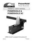
PowerHold
®
Vehicle Restraint
OWNER’S / USER’S MANUAL
Low Amp Draw Motor 8/2012 present
POWERHOLD &
POWERHOLD SC
POWERAMP • Division of Systems, Inc. • W194 N11481 McCormick Drive • Germantown, WI 53022
800.643.5424 • fax: 262.255.5917 • www.docksystemsinc.com • [email protected]
Printed in U.S.A.
Copyright © 2014
Manual No. 4111-0016
January 2014
Table of Contents
Page
Safety
Recognize Safety Information .............................................................
General Operational Safety Precautions ............................................
Operational Safety Precautions...........................................................
Maintenance Safety Precautions .........................................................
Safety Decals .........................................................................................
Owner’s/User’s Responsibilities .........................................................
1
1
2
4
5
7
Introduction
General Information .............................................................................. 8
Theory .................................................................................................... 9
Installation
PowerHold Installation Overview ........................................................10
Component Identification .................................................................... 12
Operation
Operating Instructions .......................................................................
Sequence of Operation.......................................................................
PowerHook Light Sequence ..............................................................
Placecard .............................................................................................
14
15
16
17
Maintenance
Service Dock Leveler/Restraint Safely ............................................. 18
Periodic Maintenance ......................................................................... 20
Adjustment And Testing
Testing PowerHook Operating Range .............................................. 22
Adjust Dock Leveler and Vehicle Restraint Interlock ..................... 24
Adjust Auto Return To Dock (ARTD) ................................................ 26
Troubleshooting
Troubleshooting ..................................................................................
PLC Troubleshooting .........................................................................
Electrical Drawings .............................................................................
Programming .......................................................................................
Manual Release ...................................................................................
29
36
37
40
41
Parts
Valve Blocks ........................................................................................
PowerHold Break Down .....................................................................
Power Pack Assembly Self Contained .............................................
Latch Assembly ..................................................................................
Power Pack Assembly Remote Mount..............................................
Outside Signs ......................................................................................
Outside lights ......................................................................................
42
44
46
47
48
50
51
Miscellaneous
Customer Information ........................................................................ 53
Warranty................................................................................ Back Cover
2
4111-0016 — January 2014
SAFETY
Recognize Safety Information
General Operational Safety
Precautions
Safety-Alert Symbol
The Safety-Alert Symbol identifies important safety
messages on equipment, safety signs, in manuals,
or elsewhere. When you see this symbol, be alert
to the possibility of personal injury or death. Follow
the instructions in the safety message.
Read and understand the operating instructions and
become thoroughly familiar with the equipment and
its controls before operating the dock leveler.
Never operate a dock leveler while a safety device or
guard is removed or disconnected.
The use of the word DANGER signifies the
presence of an extreme hazard or unsafe practice
which will most likely result in severe injury or
death.
The use of the word WARNING signifies the
presence of a serious hazard or unsafe practice
which may result in serious injury or death.
The use of the word CAUTION signifies possible
hazard or unsafe practice which could result in
personal injury.
IMPORTANT
The use of the word IMPORTANT is to draw
attention to a procedure that needs to be followed
to prevent machine damage.
Never remove DANGER, WARNING, or CAUTION
signs or decals on the equipment unless replacing
them.
on
Z
ng
ati
e
er
Op
ra
e
Op
g
tin
ne
Zo
Do not start the equipment until all unauthorized
personnel in the area have been warned and have
moved outside the operating zone.
Remove any tools or foreign objects from the
operating zone before starting.
Keep the operating zone free of obstacles that could
cause a person to trip or fall.
4111-0016 — January 2014
1
SAFETY
Operational Safety Precautions
Learn the safe way to operate this equipment. Read and understand the
manufacturer’s instructions. If you have any questions, ask your supervisor.
Stay clear of dock leveling device when transport
vehicle is entering or leaving area.
Chock/restrain all transport vehicles. Never
remove the wheel chocks until loading or
unloading is finished and driver has been given
permission to drive away.
Do not move or use the dock leveling device if
anyone is under or in front of it.
Do not use a broken or damage dock leveling
device. Make sure proper service and
maintenance procedures have been performed
before using.
Keep hands and feet clear of pinch points. Avoid
putting any part of your body near moving parts.
Make sure lip overlaps onto the transport vehicle
at least 4 in. (102 mm).
Keep a safe distance from both side edges.
2
4111-0016 — January 2014
SAFETY
Do not use dock leveling device if transport
vehicle carrier is too high or too low.
Do not overload the dock leveling device.
Do not operate any equipment while under the
influence of alcohol or drugs.
Do not leave equipment or material unattended on
dock leveling device.
4111-0016 — January 2014
3
SAFETY
Maintenance Safety Precautions
ALWAYS disconnect electrical power source and
ground wire before welding on dock leveler.
DO NOT ground welding equipment to any
hydraulic or electrical components of the dock
leveler. Always ground to the dock leveler frame.
Failure to follow these instructions may result in
damage to dock leveler and/or serious personal
injury or death.
Hydraulic and electrical power must be OFF when
servicing the equipment. For maximum protection,
use an OSHA approved locking device to lock
out all power sources. Only the person servicing
the equipment should have the key to unlock the
device.
DO NOT grind or weld if hydraulic fluid or other
flammable liquid is present on the surface to be
ground or welded
DO NOT grind or weld if uncontained hydraulic
fluid or other flammable liquid is present. Stray
sparks can ignite spills or leaks near the work area.
Always clean up the oil leaks and spills before
proceeding with grinding or welding.
Always keep a fire extinguisher of the proper type
nearby when grinding or welding.
Always post safety warnings and barricade
the work area at dock level and ground level
to prevent unauthorized use of the unit before
maintenance is complete.
Failure to follow these instructions may result in
serious personal injury or death.
ALWAYS stand clear of dock leveler lip when
working in front of the dock leveler. Failure to do
this may result in serious personal injury or death.
DANGER
The maintenance prop must be in the upright
“service” position when working under the dock
leveler. For maximum protection, use an OSHA
approved locking device to lock the maintenance
prop in the service position. Only the person
servicing the equipment should have the key to
unlock the device.
4
Arc Flash and
Shock Hazard
PPE (Personal Protection
Equipment) Required
De-energize equipment before
working on or inside. Do not
open cover without appropriate
PPE. Refer to NFPA 70E for
PPE requirements. This panel
may contain more than one
power source.
Hazardous Voltage
Will Cause Severe
Injury or Death
4111-0016 — January 2014
SAFETY
Dock Leveler Safety Decals
Every 90 days (quarterly) inspect all safety labels and tags to
ensure they are on the dock leveler and are easily legible. If any
are missing or require replacement, please call 1-800-643-5424
for replacements.
DANGER
CRUSH HAZARD
Maintenance prop must
support leveler behind bar.
Do not force maintenance
prop forward of bar to
support lip. Failure to
comply will result in death or
serious injury. Refer to
owner’s/user’s manual for
proper use.
1751-0727
1751-0727 Rev A
1751-0730 (x2)
SAFETY INFORMATION
DANGER
Unsupported dock leveler
ramps can lower unexpectedly.
Before allowing vehicle to leave
the dock always:
!
Ensure no equipment,
material or people are on
dock leveler.
!
Return dock leveler to its
stored position at dock level.
Failure to follow posted instructions will result in death or serious injury.
OPERATION
1. Read and follow all instructions and
warnings in owner’s/user’s manual.
2. Use of dock leveler restricted to
trained operators
3. Always chock trailer wheels or
engage truck restraint before
operating dock leveler or beginning to
load or unload.
4. Never use hands or equipment to
move ramp or lip
5. Before activating dock leveler:
! Ensure trailer is backed in against
bumpers.
! Remove any end loads if required.
! Check trailer alignment to avoid lip
interference. If lip does not lower to
trailer bed, reposition vehicle.
6. Ensure truck bed supports extended
lip or leveler frame supports the ramp
before driving on ramp.
7. Stay clear of hinges and front and
sides of moving dock leveler.
8. N e v e r u s e d a m a g e d o r
malfunctioning dock leveler. Report
problems immediately to supervisor.
MAINTENANCE/SERVICE
1. Read and follow all instructions,
warnings and maintenance
schedules in the owner’s/user’s
manual.
2. Maintenance/Service of dock leveler
restricted to trained personnel.
3. Place barriers on the driveway and
dock floor to indicate service work is
being performed.
4. DO NOT ENTER PIT unless dock
leveler is securely supported by
maintenance prop.
5. If electrically powered turn off and use
OSHA lockout/tagout procedures.
Call 262.255.1510 for replacement placards, warning labels, or owner’s/user’s manuals.
(decal placed in same position on both sides)
1751-0329 (x2)
DO NOT
FORK THIS SIDE
(decal placed in same position on both sides)
FORK
HERE
1751-0330 (x2)
(decal placed in same position on both sides)
1751-0728
DANGER
CRUSH HAZARD
Do not remove main springs until leveler is securely supported by a
suitable lifting device. Main springs contain stored energy. Be sure springs
are fully unloaded and ends are loose before removal. Failure to comply
will result in death or serious injury. Refer to owner’s/user’s manual for
proper maintenance procedure.
1751-0728 Rev A
1751-0788
DANGER
CRUSH HAZARD
Do not work under dock leveler unless this maintenance prop has been secured in the upright
position. Failure to comply will result in death or serious injury. See owner’s/user’s manual for proper
1751-0788 Rev A
procedures.
DANGER
1751-0789
CRUSH HAZARD
Open the pin latch and insert
through the maintenance
prop housing and prop
completely. Close the pin latch
to secure prop. Use every
time dock leveler is serviced.
Failure to comply will result
in death or serious injury.
1751-0789
DANGER
CRUSH HAZARD
1751-0726
DO NOT ENTER PIT unless dock leveler is
securely supported by maintenance prop. Place
barriers on driveway and dock floor to indicate
service work being performed. Failure to comply
will result in death or serious injury. Refer to
owner’s/user’s manual for proper maintenance
procedures.
1751-0726 Rev A
Note:
This is a example of dock leveler safety decals. See manual for your specific model for correct
safety decal sheet or consulate Tech Serves
4111-0016 — January 2014
5
SAFETY DECALS
Every 90 days (quarterly) inspect all safety labels and tags to
ensure they are on the dock leveler and are easily legible. If any
are missing or require replacement, please call 1-800-643-5424
for replacements.
DANGER
CRUSH HAZARD
Maintenance prop must
support leveler behind bar.
Do not force maintenance
prop forward of bar to
support lip. Failure to
comply will result in death or
serious injury. Refer to
owner’s/user’s manual for
proper use.
1751-0727
1751-0727 Rev A
1751-0730 (x2)
SAFETY INFORMATION
DANGER
Unsupported dock leveler
ramps can lower unexpectedly.
Before allowing vehicle to leave
the dock always:
!
Ensure no equipment,
material or people are on
dock leveler.
!
Return dock leveler to its
stored position at dock level.
Failure to follow posted instructions will result in death or serious injury.
OPERATION
1. Read and follow all instructions and
warnings in owner’s/user’s manual.
2. Use of dock leveler restricted to
trained operators
3. Always chock trailer wheels or
engage truck restraint before
operating dock leveler or beginning to
load or unload.
4. Never use hands or equipment to
move ramp or lip
5. Before activating dock leveler:
! Ensure trailer is backed in against
bumpers.
! Remove any end loads if required.
! Check trailer alignment to avoid lip
interference. If lip does not lower to
trailer bed, reposition vehicle.
6. Ensure truck bed supports extended
lip or leveler frame supports the ramp
before driving on ramp.
7. Stay clear of hinges and front and
sides of moving dock leveler.
8. N e v e r u s e d a m a g e d o r
malfunctioning dock leveler. Report
problems immediately to supervisor.
MAINTENANCE/SERVICE
1. Read and follow all instructions,
warnings and maintenance
schedules in the owner’s/user’s
manual.
2. Maintenance/Service of dock leveler
restricted to trained personnel.
3. Place barriers on the driveway and
dock floor to indicate service work is
being performed.
4. DO NOT ENTER PIT unless dock
leveler is securely supported by
maintenance prop.
5. If electrically powered turn off and use
OSHA lockout/tagout procedures.
Call 262.255.1510 for replacement placards, warning labels, or owner’s/user’s manuals.
(decal placed in same position on both sides)
1751-0329 (x2)
DO NOT
FORK THIS SIDE
(decal placed in same position on both sides)
FORK
HERE
1751-0330 (x2)
(decal placed in same position on both sides)
! DANGER
1751-0138
CRUSH HAZARD
DO NOT REMOVE hydraulic cylinder until leveler is
safely supported by maintenance prop. Refer to
owner’s/user’s manual for proper maintenance
procedure. Failure to comply will result in death or
serious injury.
1751-0729
DANGER
CRUSH HAZARD
Do not work under dock leveler unless this maintenance prop has been secured in the upright
position. Failure to comply will result in death or serious injury. See owner’s/user’s manual for proper
procedures.
1751-0729 Rev A
DANGER
CRUSH HAZARD
1751-0731
Rotate prop to maintenance
position. Open the pin latch
and insert through the
maintenance prop housing.
Close the pin latch to secure
prop. Use every time dock
leveler is serviced. Failure to
comply will result in death
or serious injury.
1751-0731 Rev A
DANGER
CRUSH HAZARD
1751-0726
DO NOT ENTER PIT unless dock leveler is
securely supported by maintenance prop. Place
barriers on driveway and dock floor to indicate
service work being performed. Failure to comply
will result in death or serious injury. Refer to
owner’s/user’s manual for proper maintenance
procedures.
1751-0726 Rev A
Note:
This is a example of dock leveler safety decals. See manual for your specific model for correct
safety decal sheet or consulate Tech Serves
6
4111-0016 — January 2014
OWNER’S/USER’S RESPONSIBILITIES
1. The owner/ user should recognize the inherent dangers of the interface between the loading dock and the
transportation vehicle. The owner/ user should, therefore, train and instruct all operators in the safe operation
and use of the loading dock equipment in accordance with manufacturer’s recommendations and industry
standards. Effective operator training should also focus on the owner’s/user’s company policies and operating
conditions. Maintaining, updating and re training all operators on safe working habits and operation of the
equipment, regardless of previous experience, should be done on a regular basis and should include an
understanding and familiarity with all functions of the equipment. Owner’s/user’s shall actively maintain,
update and retrain all operators on safe working habits and operations of the equipment.
2. The manufacturer shall provide to the initial purchaser all necessary information regarding Safety Information,
Operation, Installation and Safety Precautions, Recommended Initial and Periodic Inspections Procedures,
Planned Maintenance Schedule, Product Specifications, Troubleshooting Guide, Parts Break Down, Warranty
Information, and Manufacturers Contact Information, as well as tables to identify the grade(slope) for all
variations of length or configuration of the dock leveling device and information identifying the maximum
uncontrolled drop encountered when sudden removal of support while in the working range of the equipment.
3. It is recommended that when the transportation vehicle is positioned correctly in the dock opening and in
contact with both bumpers, there shall be a minimum of 4.00 inches (100mm) overlap of the leveling device
and the transportation vehicle at all times during the loading and unloading process.
4. The Owner/User must review all name plates, placards, decals, instructions and posted warnings and place
the same in view of the operator or maintenance personnel for whom such warnings are intended for. Contact
manufacturer for any replacements.
5. Manufacturer’s recommended periodic maintenance and inspection procedures in effect at the date of
shipment shall be followed at all times. Written documentation of maintenance, replacement parts or damage
should be retained. In the event of damage notification to the manufacturer is required.
6. Loading dock equipment that has been structurally damaged or has experienced a sudden loss of main support
while under load (such as what might occur when a transport vehicle pulls out from under the leveling device)
shall be removed from service, inspected by a manufacturer’s authorized representative, and repaired or
replaced as needed before being placed back in service.
7. Any modifications or alterations of loading dock equipment shall only be done with prior written approval from
the manufacturer and the same shall be at least as safe as the original equipment was prior to the modification
and shall also satisfy all safety requirements of the manufacturer for the particular application of the leveling
device.
8. When industrial moving devices are being used in the loading or unloading of product from the transportation
vehicle, this vehicle shall have the brakes and wheel chocks applied appropriately or all other positive
restraining device shall be fully utilized. It is recommended that trailers with air-ride suspension systems shall
have its air exhausted prior to performing loading and unloading operation to minimize trailer bed drop.
9. Loading dock safety equipment should never be used outside of its intended use, vertical working range, or
capacity. Please consult the manufacturer if you have any questions as to the use, vertical working range or
capacity of the equipment. Only properly trained and authorized personnel should operate the equipment.
10. When selecting loading dock safety equipment, it is important to consider not only present requirements but
also future plans and any possible adverse conditions, environmental factors or usage.
4111-0016 — January 2014
7
INTRODUCTION
Congratulations on your choice of a Poweramp PowerHold vehicle restraint. This manual covers the
PowerHold vehicle restraint operating system.
Designed by Poweramp to be a marvel of simplicity
and efficiency, your vehicle restraint, when properly
installed, will provide many years of troublefree performance with an absolute minimum of
maintenance. Its revolutionary hydraulic system
efficiently controls and operates every function. To
obtain maximum performance and longest possible
use, a simple program of preventive maintenance is
recommended and is outlined in this manual.
The PowerHold vehicle restraint is designed to seek,
find and maintain a tight, continuous hold on the
RIG (Rear Impact Guard) bar, effectively eliminating
“trailer creep”. As an optional safety feature, the
dock leveler and vehicle restraint can be interlocked,
preventing operation of the dock leveler until the hold
engages the ICC (RIG bar).
The vehicle restraint is firmly anchored to the drive
way approach or the building wall for maximum
holding power. The PowerHold restraint is designed
to withstand a pulling force of 30,000 lbs.
The PowerHold vehicle restraint comes equipped
with an electrical control panel, which allows push
button operation of the vehicle restraint functions.
When combining a Poweramp Dock Leveler with a
PowerHold vehicle restraint, the control panel will
allow for operation of both units in the same control
panel.
Each PowerHold, Poweramp Dock Leveler and
control panel has been factory prewired and tested to
ensure satisfactory operation.
To illustrate which connections are to be made
in the field at installation, electrical drawings are
included with each order or by contacting Poweramp
Technical Services.
Once again, thank you and congratulations on
your purchase of a Poweramp PowerHold vehicle
restraint.
Due to ongoing product improvement, some parts have changed, along with operation and trouble shooting
methods. For further assistance, please contact:
Poweramp Technical Service at 800-643-5424 or [email protected]
8
4111-0016 — January 2014
OPERATION
When the Engage button (A) is pushed on the
control panel this activates an electric motor which,
drives a hydraulic pump. The hydraulic pump forces
oil into the hydraulic cylinder causes the shoe to
rotate upward.
The shoe will make contact with the ICC bar. The
pump will shut off once the shoe is at 90deg. Once
the vehicle is locked, the leveler Raise button will be
activated(D).
When the Release button (B) is pushed the motor
will run and lower the shoe. After the shoe is stored
the pump will turn off (only on units with stored
switch).
If no ICC Bar is preset PowerHold can be operated
in Bypass (C).
A
B
C
D
4111-0016 — January 2014
9
INSTALLATION
PowerHold Installation Overview
For comprehensive installation instructions of the PowerHold
read and understand the Installation and Operation Manual.
POWERPACK LOCATION OPTIONS
Coordinate powerpack location and hose
length for proper placement.
Allow
Enough
Clearance
for Possible
Seal or
Shelter
Dock Face (Self Contained)
Appropriate location when the likelihood of
flooding, snow removal and damage from
trailer/trucks is minimal. Also recommended
for use with non-hydraulically powered dock
levelers.
Under The Dock Leveler
When combined with hydraulic leveler pump or
remotely mounting under leveler, make certain
to locate the powerpack where leveler will not
interfere in below dock conditions. The routing
of hydraulic and electrical lines from the
powerpack to the restraint are best placed
through min. 3” PVC (hydraulic) and 3/4”
conduit (electrical)
chase during pit
construction.
POWERHOLD REMOTE MOUNT POWERPACK
IO PH PR 12/13
Inside Building (Remote Mount)
Locate powerpack to minimize
obstruction potential. Hydraulic and
electrical lines from the powerpack
to the restraint are best placed
through min. 3” PVC (hydraulic)
and 3/4” (electrical) chase during pit
construction.
10
4111-0016 — January 2014
INSTALLATION
PowerHold Installation Overview
For comprehensive installation instructions read and understand the
Installation and Operation Manual.
Concrete Dock Face
(Standard installation)
Wedge Anchors Method
Weld Plate Embed Method
Using back plate as a guide, drill six (6) holes
for wedge anchors (3/4”x 5 1/4” min.) (Kit
#2103-0003)
Weld three sides of PowerHold back plate to the
optional embed mounting plate (Part #7953-0119)
with continuous 1/4” fillet weld.
20”
5 1/4” minimum
20”
Embed
Plate
located 2”
above grade
3/8”
Cantilevered Dock
(For bumper projection >4” or cantilevered dock or Edge-of-Dock leveler)
To determine size offset required, take total effective
bumper projection (bumper size plus any cantilever) and
subtract 4”.
Driveway Mount
Dim. A
Offset Formula
Dim. A
Dim. B
Bumper Projection
Cantelever
4"
6"
10"
15"
Offset
Wall Mount
Determine offset
then proceed with
“Driveway Mount”
instructions below.
For filler requirements from 1 ½”to
Dim. A 7 ½” use cantilever bracket #94140054 and anchor cantilever bracket
to the dock face or weld to
embedded mounting plate (Part
#7953-0119)
Dim. B
+ Dim B
+ Dim B
-4" = Offset
+ Dim B
+ Dim B
For filler requirements for 8 3/4” to
Dim. B 13 3/4” use cantilever bracket
33”
#9414-0055 and anchor cantilever
bracket to the dock face (3/4” Dia.
X 5 1/4” min.) (Kit #2103-0003) or
weld to embedded mounting
Plate (Part #7953-0119).
10”
8” Min.
48”
Dim. B
Dim. B
Driveway Mount
(Recommended when dock face is unsuitable for PowerHold Mounting)
Wedge Anchors Method
(Kit #2103-0003)
Driveway mount requires attachment to
a concrete drive greater than 8” thick.
For asphalt drive, pour 48”x48”x8”
(min.) concrete pad and include six (6)
3/4” dowels into foundation wall. Then
proceed with adhesive anchors or weld
plate embed.
Install six (6) 3/4” Dia. x 5 1/4”
min. wedge anchors at the base
of the PowerHold.
Drive Embed Method
Weld method
Properly locate and level the drive embed weld
plate (Part#7953-0132) in the drive approach.
Observe Cantilever conditions for proper
positioning. Weld restraint to embed plate with a
continuous ¼” filet weld.
14”
8” Min.
48”
36”
48”
A continuing product improvement process is in effect at Systems, Inc. We reserve the right to make product changes without prior notice.
Poweramp • Division of Systems, Inc. • W194 N11481 McCormick Dr. • Germantown, WI 53022
800.643.5424 • fax: 262.255.4199 • www.DockSystemsInc.com
4111-0016 — January 2014
11
INSTALLATION
Component Identification.
F
E
J
H
B
G
D
I
A
C
A —Weldment
B —Latch Assembly
C —Hydraulic Cylinder
D — Power Pack SC Only
E — Valve Block
F — Shoe
G — Rack Weldment
H — Slide Block
I — Push Rod
J — Spring
“TWIDO” Programmable Logic Controller
12
4111-0016 — January 2014
INSTALLATION
Component Identification
PowerHold manifold with leveler hose connections.
Diverter valve, When coil is
energized directs fluid to the
PowerHold
Pressure to PowerHold
Pressure From Pump
Pressure To Logic Block
Return To Pump
Return From PowerHold
Return To Logic Block
4111-0016 — January 2014
13
OPERATION
Operating Instructions
Stay clear of dock leveler when transport vehicle
carrier is entering or leaving dock area.
DO NOT move or use the dock leveler if anyone is
under or in front of leveler.
Keep hands and feet clear of pinch points. Avoid
putting any part of your body near moving parts.
Failure to follow these instructions may result in
severe personal injury or death.
Only trained personnel should operate the dock
leveler and vehicle restraint.
DO NOT overload the dock Leveler.
DO NOT operate any equipment while under the
influence of alcohol or drugs.
DO NOT leave equipment or material unattended
on the dock leveler.
Failure to follow these instructions may result in
personal injury and/or damage to equipment.
DANGER
DO NOT use a broken or damaged dock leveler
or vehicle restraint. Make sure proper service and
maintenance procedures have been performed on
equipment before using.
Transport vehicles wheels must be chocked unless
the vehicle restraint is used. Never remove the
wheel chocks until loading/unloading is finished
and transport vehicle has been given permission to
leave.
Make sure platform lip rests on the transport
vehicles bed with at least 4 in. (102 mm) of
overlap.
Maintain a safe distance from side edges of leveler
during the loading/unloading process.
Arc Flash and
Shock Hazard
PPE (Personal Protection
Equipment) Required
De-energize equipment before
working on or inside. Do not
open cover without appropriate
PPE. Refer to NFPA 70E for
PPE requirements. This panel
may contain more than one
power source.
Hazardous Voltage
Will Cause Severe
Injury or Death
Failure to follow these instructions may result in
serious personal injury or death.
14
4111-0016 — January 2014
OPERATION
SEQUENCE OF OPERATION NORMAL
SEQUENCE OF OPERATION BYPASS
1. Check that the transport vehicle is positioned
squarely against the dock bumpers.
- Inside Red Light
- Outside Green Light
1. Check that the transport vehicle is positioned
squarely against the dock bumpers.
2. Push ENGAGE button to activate restraint.
- Inside Green and Yellow Light
- Outside Red Light
3. ENGAGED on vehicle Restraint.
- Inside Green Light
- Outside Red Light
4. Visually inspect restraint for proper engagement.
If RIG (Rear Impact Guard) is damaged or
missing, dock leveler can be used in BYPASS
IF BYPASS MODE IS REQUIRED
SEE: SEQUENCE OF OPERATION - BYPASS
FOR NORMAL OPERATION AFTER TRAILER RIG
IS ENGAGED CONTINUE WITH: STEP 5
2. Push ENGAGE button to activate restraint.
- Inside Green Light, Red Outside Light
3. Visually inspect restraint for proper engagement.
If RIG (Rear Impact Guard) is damaged or missing
dock leveler can be used in BYPASS.
4. If RIG (Rear Impact Guard) is damaged or
missing, Shoe will automatically return to the
stored position.
- Inside Amber Light and LED will flash for 30
seconds, then Flash Red (Do Not Enter).
- Outside Red Light will flash for 30 seconds, then
flash Green
5. Secure transport vehicle wheels with wheel chock.
6. Use key to activate BYPASS mode.
- Inside Green Light with Amber Caution Light
- Outside Red Light
5. Position dock leveler onto transport vehicle.
7. Position dock leveler onto transport vehicle trailer
6. When loading or unloading is complete, return
dock leveler to the stored position.
7. Release vehicle restraint and/or remove chocks
from transport vehicle wheel.
8. When loading or unloading is complete, return
dock leveler to the stored position.
-Inside Green Light with Amber Caution Light
-Outside Red Light
9. Reset BYPASS mode to NORMAL mode by
pressing the ENGAGE button once.
- Inside Red Light, Amber turns Off
- Outside Green Light
- Pressing the ENGAGE button during any part of
the cycle will end the ENGAGE mode
- Pressing the LOCK button a second time will
cycle the PowerHold.
10. Un-chock the transport vehicle wheel when
transport vehicle is ready to depart.
4111-0016 — January 2014
15
OPERATION
PowerHold Light Sequence
CONDITION
LIGHTS
INSIDE
OUTSIDE
STORED BEGIN/END
(O/9)
RED
(O/8)
GREEN
IN MOTION
(O/6)
AMBER
(O/7),(O/6)
RED/(OPTIONAL STROBE)
LOCKED
(O/5)
GREEN
(O/7)
RED
BYPASS
(O/5),(O/6)
GREEN/AMBER
(O/7),(O/6)
RED/(OPTIONAL STROBE)
MISSED ICC
(O/6)
22sec (O/4)
AMBER (TIME) RED
(O/7) 22sec (O/8)
RED (TIME) GREEN
(OPTIONAL STROBE) (0/8)
TIMEOUT (FAILURE)
(O/9),(O/6)
RED/AMBER
(O/7),(O/6)
RED/(OPTIONAL STROBE)
(O/8)
AMBER
(O/5)...8sec..(O/8)
RED/(OPTIONAL STROBE)
TIMEOUT (FAILURE)
IN MOTION
A NEW LOCK CYCLE OR BYPASS WILL OVERRIDE MISSED ICC
TIMEOUT FAILURE OVERRIDE MISSED ICC
EMERGENCY STOP (Where Equipped) OVERRIDES EVERY OTHER CONDITION
(O/4)
WHEN E-STOP IS DEPRESSED
(O/5)
RED
RED
RESET BYPASS, PRESS THE RELEASE BUTTON
LEGEND
(O,9) = First number indicates PLC output lights, second tell’s output light that’s activated
16
4111-0016 — January 2014
PLACECARD
Placard Installation Instructions
• Owner is responsible for the installation and placement of product placards.
• Make sure placard is in plain view of dock leveler operations.
• Suggested placement of placard is near control box attached to electrical
conduit by using nylon tie. If there is no control box present, mount placard
on wall to the immediate left of leveler at eye level.
Control Box
Placard
Nylon Tie
(Placard placement
shown as reference
only.)
Conduit
4111-0016 — January 2014
17
MAINTENANCE
Service Dock Leveler Safely
D
A
B
C
C
B
A— Maintenance Prop
B— Tag Out Device
When service under the dock leveler is required,
always lock all electrical disconnects in the OFF
position after raising the platform and engaging the
maintenance prop. Failure to do this may result in
serious personal injury or death.
Always stand clear of the dock leveler lip when
working in front of the dock leveler.
The maintenance prop MUST be in the service
position when working under the dock leveler.
For maximum protection, use an OSHA approved
locking device to lock the maintenance prop in
the service position. Only the person servicing
the equipment should have the key to unlock the
maintenance prop.
Unless the dock leveler is equipped with a tethered
remote, two people are required to engage the
maintenance prop: one person to operate the unit,
the other person to engage the maintenance prop.
Failure to follow these instructions may result in
serious personal injury or death.
C — Lock Out Device
D — Front Header
Always post safety warnings and barricade the
work area at dock level and ground level to prevent
unauthorized use of the dock leveler before
maintenance is complete. Failure to do this may
result in serious personal injury or death.
Whenever maintenance is to be performed under
the dock leveler platform, support the platform with
maintenance prop (A). Position the maintenance
prop behind front header plate (D) while staying clear
of the lip. The lip will fold down after the platform
has rested on the maintenance prop. Lock the
maintenance prop in the service (upright) position
using an OSHA approved lockout device* (C) and tag
out device(B).
Whenever servicing the dock leveler, lock the
electrical power disconnect in the OFF position. Use
only an OSHA approved lockout device* (C) and tag
out device (B).
Only the person servicing the equipment should have
the capability to remove the lockout devices. The tag
out devices* must inform that repairs are in process
and clearly state who is responsible for the lockout
condition.
* Refer to OSHA regulation 1910.146.
* Refer to OSHA regulation 1910.147.
18
4111-0016 — January 2014
MAINTENANCE
Periodic Maintenance
Apply Moly Alumaplex Ep grease or equivalent
IMPORTANT
Daily Maintenance
• Make sure that all the Inside and Outside signal
lights work.
Failure to properly lubricate the vehicle restraint
will cause abnormal operation of the restraint
Weekly Maintenance
• Operate the PowerHold vehicle restraint through
the complete operating cycle to maintain
lubrication.
NOTE: - position.
Apply lubricant
• Inspect the slide block track and push rod areas.
The areas must be kept free of dirt and debris.
Build-up of foreign material in the track areas will
cause abnormal operation.
Quarterly Maintenance
• Clean and Lubricate slide block track and push rod
areas. Lubricate pins for the “Z” bar. Inspect and
clean Prox switches.
Yearly Maintenance
• Repeat of Quarterly Maintenance.
• Change Hydraulic Oil (May be required earlier
depending on conditions).
4111-0016 — January 2014
19
MAINTENANCE
Periodic Maintenance With Leveler
C
B
A
On select models an inspection
plate is provided in the platform
floor for ease of maintenance and pit
inspection. Others must be serviced
from under the leveler.
D
K
J
E
H
F
L
G
L
A— Lip Hinge Area
D— Dual-Lanyard Lever Pivot
B— Valve Lever Pivot on Logic E— Platform Hinge Area
Block
F— Frame Cylinder Trunnion
C— Inspection Plate
Before performing any maintenance under the
dock leveler, lock the electrical power source in
OFF position and lock the maintenance prop in the
service position using an approved locking device.
(See Service Dock Leveler Safely in this section.)
Failure to follow these instructions may result in
serious personal injury or death.
IMPORTANT
Use of fluids that do not have equivalent
specifications to those in the following list will result
in abnormal operation of the dock leveler and
voiding of warranty.
20
G — Toe Guard Hinges
H— Platform Cylinder-to-Platform Pin
J— Lip Cylinder-to-Platform Pin
K— Lip Lifter and Lip
Cylinder Pin
L — Toe Guard cams
To ensure normal operation of the restraint or dock
leveler, use only aircraft hydraulic fluid designed to
meet or exceed military specification MIL-H-5606-G.
It is recommended that the following hydraulic fluids
be used:
•
•
•
•
•
ULTRA-VIS-HVI-15
Aero Shell Fluid 4 or Fluid 41
Mobile Aero HFA Mil-H5606A or Aero HF
Texaco Aircraft Hydraulic Oil 15 or 5606
Exxon Univis J13
These fluid brands can be mixed together. Mixing
with fluids that do not meet or exceed MIL-H-5606-G
may damage the equipment and WILL void warranty.
Use of hydraulic fluids with equivalent specifications
to those listed here are acceptable.
4111-0016 — January 2014
MAINTENANCE
P
Daily Maintenance
• Make sure that all the Inside and Outside signal
lights work.
N
Q
Weekly Maintenance
• Operate the dock leveler and PowerHold
through the complete operating cycle to maintain
lubrication.
NOTE: To thoroughly inspect the platform hinge
area, put the platform in the full below-dock
position.
M
• Inspect the platform hinge and the lip hinge areas.
The hinge areas must be kept free of dirt and
debris. Build-up of foreign material in the hinge
areas will cause abnormal operation.
Quarterly Maintenance
IMPORTANT
Failure to properly lubricate the dock leveler will
cause abnormal operation of the leveler.
• Lubricate the following areas with light weight
machine oil:
(A)— Lip hinge area unless equipped with grease
fittings (apply oil to the top of the entire
length of lip hinge when platform is at the full
below-dock position and lip is folded).
(D)— Dual-lanyard lever pivot.
(E)— Platform hinge area (apply oil to top of all
platform hinges when platform is at the full
below-dock position).
(G)— Toe guard hinges (along full length of top
and bottom hinges).
(H)— Platform cylinder-to-platform frame pin.
(J)— Lip cylinder-to-platform frame pin.
(K)— Lip lifter and lift cylinder pin.
• Lubricate the following areas with white lithium
grease:
(B)— Valve lever pivot and top of logic block spool
valve.
(F) — All platform cylinder trunnions.
(L)— Toe guard pivots (where toe guard strut
contacts pivot).
NOTE: Apply grease to lip hinge grease fittings if
equipped.
4111-0016 — January 2014
M — Reservoir
N — 2 in. (51 mm) (From Top of
Reservoir)
P — Breather Cap
Q — Fluid Level
IMPORTANT
A low fluid level or the use of hydraulic fluids not
equivalent to the fluid types recommended, will
cause abnormal operation of the leveler and WILL
void warranty.
• Check reservoir fluid level (Q):
1. Put the dock leveler platform at the full belowdock position.
2. Turn OFF all electrical power to the leveler.
3. Remove inspection plate (C).
4. Remove breather cap (P).
5. Measure fluid level. The fluid level should be
approximately 2 in. (51 mm) (N) from top of
reservoir (M) with platform at the below-dock
position.
6. Add hydraulic fluid if necessary. Use only
recommended fluid.
7. Install breather cap and inspection plate.
8. Turn ON electrical power to the leveler.
9. Return the platform to the cross-traffic position.
21
ADJUSTMENT AND TESTING
PowerHold Operating Range
NOTE: Test operating range of PowerHold without
transport vehicle backed into dock.
When service under the dock leveler is required,
always lock all electrical disconnects in the OFF
position after raising the platform and engaging the
maintenance prop. Failure to do this may result in
serious personal injury or death.
1. Make sure the selector switch is in Normal and
BYPASS mode has not been activated.
- Red Inside Light, No Amber Light
- Green Outside Light
Always post safety warnings and barricade the
work area at dock level and ground level to prevent
unauthorized use of the dock leveler before
maintenance is complete. Failure to do this may
result in serious personal injury or death.
2. Momentarily press the ENGAGE button. The
PowerHold restraint will raise to 90 deg. NO
transport vehicle the restraint will lower back to
the stored position and shut off.
- Inside Amber Light for 30 seconds, then Red
*Alarm will sound if equipped
- Outside Red Light for 30 seconds, then Green
Operating range Refer to page 10.
Always stand clear of the dock leveler lip when
working in front of the dock leveler.
The maintenance prop MUST be in the service
position when working under the dock leveler.
For maximum protection, use an OSHA approved
locking device to lock the maintenance prop in
the service position. Only the person servicing
the equipment should have the key to unlock the
maintenance prop.
Unless the dock leveler is equipped with a tethered
remote, two people are required to engage the
maintenance prop: one person to operate the unit,
the other person to engage the maintenance prop.
Failure to follow these instructions may result in
serious personal injury or death.
Follow the installation instructions found
in the PowerHold Installation & Operation
Manual prior to attempting any adjustments.
22
4111-0016 — January 2014
ADJUSTMENTS
PowerHold Adjustments
Stored prox switch
No adjustments required.
Prox Switch PRS 2
INPUT #4
Install prox flush then back out
(CCW) just past flush.
1/16 min
1/8 max
Prox Switch PRS 1
INPUT #3
The Operating range is not adjustable on a
PowerHold restraint.
IMPORTANT: Make sure that the wire from the prox
switches are clear of all moving parts.
Proximity switch Adjustment and replacement.
A.
Locate and remove four screws and cover on
front of PowerHold assembly.
B.
Adjust PRS 1. With the “Z’” bar rotated
directly over the prox switch. The prox switch
distance should between 1/16” and 1/8”.
C.
Adjust PRS 2. The #2 prox switch must be
threaded in until flush with the latch block.
Turn prox switch out (CCW) until switch is no
longer flush with the latch block.
4111-0016 — January 2014
23
OPTIONAL EQUIPMENT ADJUSTMENTS
Adjust Dock Leveler and Vehicle Restraint Interlock
Dock leveler and vehicle restraint interlock
options
When service under the dock leveler is required,
always lock all electrical disconnects in the OFF
position after raising the platform and engaging the
maintenance prop. Failure to do this may result in
serious personal injury or death.
Always post safety warnings and barricade the
work area at dock level and ground level to prevent
unauthorized use of the dock leveler before
maintenance is complete. Failure to do this may
result in serious personal injury or death.
Always stand clear of the dock leveler lip when
working in front of the dock leveler.
The maintenance prop MUST be in the service
position when working under the dock leveler.
For maximum protection, use an OSHA approved
locking device to lock the maintenance prop in
the service position. Only the person servicing
the equipment should have the key to unlock the
maintenance prop.
RE Interlock: Dock leveler can be interlocked
with a vehicle restraint to prevent the leveler
from operating until the restraint has engaged
the transport RIG (Rear Impact Guard) when the
OPERATION switch is in NORMAL and has NOT
been switched to BYPASS.
LS Interlock: Vehicle restraint is interlocked with the
dock leveler so that the restraint cannot be operated
until the leveler is stored in the cross traffic position
(lip fully folded, inside the keepers, and the platform
level with the dock floor).
Leveler and restraint interlocking are overridden when
the OPERATION switch is in BYPASS. This allows
the independent operation of the leveler (the restraint
cannot be operated in BYPASS).
Pressing the restraint ENGAGE button when in
BYPASS mode will return the leveler to NORMAL
operating mode.
This option is not available on units equipped with the
Auto Return to Dock option.
Unless the dock leveler is equipped with a tethered
remote, two people are required to engage the
maintenance prop: one person to operate the unit,
the other person to engage the maintenance prop.
Failure to follow these instructions may result in
serious personal injury or death.
24
4111-0016 — January 2014
OPTIONAL EQUIPMENT ADJUSTMENTS
Adjust & Test Dock Leveler and Vehicle Restraint Interlock
1. The dock leveler should be in the cross traffic
position before beginning tests.
2. Back a transport vehicle with RIG bar into dock.
A test fixture may be used to simulate the RIG
bar. Use care to avoid damage to the equipment
or harm to the operator.
3. Press the RAISE push button. The dock leveler
should NOT raise. If the leveler did not raise,
proceed with step 4. If the leveler did raise,
decrease dimension “A” or “B”, so that the target
is in the sensing range of the switch. Typical
factory settings for “A” and “B” are approximately
3/4” and 1/8” respectively. Make adjustments at
switch (dimension B) and/or target (dimension
A) until leveler does not raise when the vehicle
restraint is not engaged on transport vehicle
RIG bar.
4. Momentarily press the ENGAGE button. The
vehicle restraint automatic engage cycle will
be activated and the restraint will engage the
transport vehicle RIG bar.
6. Press the RELEASE button. The vehicle restraint
should NOT disengage from the transport vehicle
RIG bar or test fixture. If the vehicle restraint did
NOT engage, proceed with step 7. If the vehicle
restraint DID disengage, move the switch farther
from the target or bend the target so that the
target is not in the sensing range of the switch
as shown in Figure 37. Make adjustments at
switch and/or target until vehicle restraint does not
disengage transport vehicle .
IMPORTANT: If adjustments are required in this
step, make sure that the interlocking described in
step 3 is still in effect after step 6 adjustments are
complete.
7. Press the RAISE push button. The dock leveler
will raise. The leveler lip will fold as the platform
raises. When the lip is fully folded, release the
RAISE push button. The leveler will descend to
the cross traffic position.
8. Momentarily press the RELEASE button. The
vehicle restraint will return to the stored position.
5. Raise the dock by pressing the RAISE button
until the lip is fully extended. Release the
RAISE button. The leveler will drop to the floor of
the transport vehicle. If a RIG test fixture is used
it should allow the leveler to drop to the full below
dock position without the contact between the lip
and test fixture.
4111-0016 — January 2014
25
OPTIONAL EQUIPMENT ADJUSTMENTS
Adjust Auto Return To Dock (ARTD)
Adjust the ARTD as Follows:
E
F
D
C
When service under the dock leveler is required,
always lock all electrical disconnects in the OFF
position after raising the platform and engaging the
maintenance prop. Failure to do this may result in
serious personal injury or death.
B
A
H
A— Cable
B— Proximity Switch
C— Bracket
D— Lock Nuts
G
E— Target
F— Lip Hinge Tube
G—Platform Lip
H— Indicator Light
Standard PR levelers are equipped with the Auto
Return To Dock (ARTD) unless leveler is interlocked
with a vehicle restraint.
The ARTD allows the platform to automatically return
to the cross-traffic (stored) position after the transport
vehicle departs. The ARTD uses a proximity switch
(B) located under the platform and a piece of angled
steel called the target (E) that is attached to the lip
hinge tube (F).
The proximity switch provides a six-second delay
after the platform has lowered to the full below-dock
position, after which, the platform will return to the
cross-traffic position. The switch also contains an
indicator light (H) that can be used for diagnosing
and adjusting the switch.
NOTE: Some proximity switches have an indicator
light at the back of the housing and some
have the light at the side of the housing.
Always post safety warnings and barricade the
work area at dock level and ground level to prevent
unauthorized use of the dock leveler before
maintenance is complete. Failure to do this may
result in serious personal injury or death.
Always stand clear of the dock leveler lip when
working in front of the dock leveler.
The maintenance prop MUST be in the service
position when working under the dock leveler.
For maximum protection, use an OSHA approved
locking device to lock the maintenance prop in
the service position. Only the person servicing
the equipment should have the key to unlock the
maintenance prop.
Unless the dock leveler is equipped with a tethered
remote, two people are required to engage the
maintenance prop: one person to operate the unit,
the other person to engage the maintenance prop.
Failure to follow these instructions may result in
serious personal injury or death.
1. Raise platform fully and engage the maintenance
prop in the service position. Allow platform to rest
on the prop so the lip will fully fold until it contacts
the lip stops.
2. Turn OFF all electrical power to the dock leveler.
Attach safety lockout and tag-out devices.
26
4111-0016 — January 2014
OPTIONAL EQUIPMENT ADJUSTMENTS
IMPORTANT
6. Turn ON electrical power to the dock leveler.
Anytime proximity switch and target are adjusted,
always check for interference between target and
switch before operating the leveler. Damage to
switch will occur if the target contacts the switch.
7. Disengage the maintenance prop.
The maximum torque for proximity switch lock nuts
is 27 N•m (29 lb-ft). Damage to switch will occur if
maximum torque is exceeded.
9. Raise the platform until the lip is fully extended,
then allow the platform to drift to the below-dock
position.
B
C
A— 1/4 in. (6.4 mm)
Approximate
B— Target
D
Use the following illustrations to assist in fine
tuning and/or diagnosing the ARTD operation.
Cross-Traffic Position
C— 1 in. (25.4 mm)
Approximate
D— Lock Nuts
E— Proximity Switch
NOTE: Distances (A and C) are typical factory
settings. Use these dimensions only as a
starting point when adjusting the proximity
switch and target, especially if switch and/or
target have been replaced.
When dimensions (A and C) are obtained,
the proximity switch and target may need
finer adjustments to get the ARTD to operate
satisfactorily.
3. Loosen lock nuts (D). Adjust proximity switch (E)
to obtain distance (A). Tighten lock nuts.
4. Bend target (B) as needed to obtain distance (C).
Recheck distance (A) and readjust if necessary.
NOTE: At least two people may be required to
manually move the lip.
5. After adjusting proximity switch and target, slowly
move the lip up by hand while observing the
target and proximity switch. The target MUST
NOT contact the switch, otherwise, damage to
switch will occur. Readjust switch and/or target if
necessary, then recheck for interference.
4111-0016 — January 2014
After approximately 6 seconds, the platform must
return to the cross-traffic position.
10. Adjust the proximity switch and target as
necessary. Make small adjustments, then
operate the dock leveler to check results. Do this
until satisfied with the ARTD operation.
A
E
8. Turn the ARTD switch (on control panel) to the
ON position.
Lip Keeper
NOTE: The platform lip is fully folded when the
platform is at the cross-traffic (stored)
position (lip engaged with keepers) or when
platform is resting on the maintenance prop.
Whenever the platform lip is at the cross-traffic
position, the following conditions will exist for a
normally operating ARTD:
• Target not in the sensing area of proximity switch.
• Proximity switch OFF (open) (no signal sent to
control panel).
• Proximity switch indicator light is OFF.
• Platform stays at this position unless the operator
activates the leveler.
27
OPTIONAL EQUIPMENT ADJUSTMENTS
Full Below-Dock Position
Lip Fully Extended Position
Lip Keeper
Whenever the platform lip is at the fully extended
position, the following conditions will exist for a
normally operating ARTD:
• Target not in the sensing area of proximity switch.
Whenever the platform lip is at the full below-dock
position, the following conditions will exist for a
normally operating ARTD:
• Proximity switch OFF (open) (no signal sent to the
control panel).
• Proximity switch indicator light is OFF.
• Proximity switch senses target.
• Proximity switch ON (closed) (signal sent to the
control panel).
• If the platform lip is resting on the truck bed,
the platform will stay at this position unless the
operator activates the leveler.
• Proximity switch indicator light is ON.
• Platform will automatically rise after approximately
a six-second delay, then returns to the cross-traffic
position.
28
4111-0016 — January 2014
TROUBLESHOOTING POWERHOLD
When service under the dock leveler is required,
always lock all electrical disconnects in the OFF
position after raising the platform and engaging the
maintenance prop. Failure to do this may result in
serious personal injury or death.
Always post safety warnings and barricade the
work area at dock level and ground level to prevent
unauthorized use of the dock leveler before
maintenance is complete. Failure to do this may
result in serious personal injury or death.
Always stand clear of the dock leveler lip when
working in front of the dock leveler.
The maintenance prop MUST be in the service
position when working under the dock leveler.
For maximum protection, use an OSHA approved
locking device to lock the maintenance prop in
the service position. Only the person servicing
the equipment should have the key to unlock the
maintenance prop.
Unless the dock leveler is equipped with a tethered
remote, two people are required to engage the
maintenance prop: one person to operate the unit,
the other person to engage the maintenance prop.
Failure to follow these instructions may result in
serious personal injury or death.
Before performing the detailed troubleshooting procedures, check the following items first:
• Check all fuses inside the control panel(s). Replace
any blown fuse(s) with a fuse of equal specification.
Symptom
Possible Cause
• Make sure the correct voltages are present at the
proper locations inside the control panel(s).
Solution
Inside and outside signal Bad Flasher.
lights do not operate.
Controller (PLC)
RUN indicator is on
solid (not flashing). Unit
operates as normal.
Replace flasher with wire. If lights operate (lights
will not flash), replace flasher.
Restraint does not
Motor overload device
operate. Motor does not tripped.
energize.
Reset overload relay (3 phase) or replace fuse (1
phase) or reset breaker (1 phase-new models).
Determine cause of device tripping.
NOTE: If replacing fuse, use fuse with equal specification
.
Motor starter (3 phase) or
motor relay (1 phase) not
energizing. Combination
Leveler and P-Hold Only.
4111-0016 — January 2014
Check controller output that sends a signal to starter
or relay. Output may have failed OPEN. Use meter
to check for contact closure when output ON.
29
TROUBLE SHOOTING POWERHOLD
Symptom
Possible Cause
Three-phase units only: 3 Phase units only - no
Restraint does not
voltage is present on one
operate. Motor energizes line.
but does not run.
NOTE: A motor that is
If motor hums, but does missing voltage on one line
not run, overload device is said to be single-phased.
should trip.
Combination Leveler and
P-Hold Only.
Solution
Check for blown fuses at branch circuit disconnect.
Replace fuse. Determine cause of blown fuse.
Check motor starter as follows:
1. Disconnect wires at load side of starter.
2. Energize the starter.
3. Measure line-to-line voltage at line side of starter.
4. Measure line-to-line voltage at load side of
starter.
5. Line-side and load-side voltages should be
approximately the same. Replace starter if
voltage values are considerably different from
one another.
Check all wiring to motor for high resistance or no
connection.
Replace motor.
Three-phase units only:
Restraint does not
operate. Motor runs in
reverse
Phase reversed.
Reverse any two legs at the branch circuit
disconnect.
Single-phase units only:
Restraint does not
operate.
Line voltage too low.
Check wiring to motor for high resistance. Check for
loose or corroded connections. Check if gauge of
wires to motor are of correct size and specification
for load requirement. Replace if necessary.
Defective motor centrifugal
switch.
Replace motor.
Defective motor capacitor.
Replace motor.
Low hydraulic fluid.
Add fluid, see Maintenance section for proper fluid
level and type.
Low hydraulic fluid.
Add fluid, see Maintenance section for proper fluid
level and type.
Motor energizes, but
does not run.
Restraint operates
slowly.
Pressure relief valve set too See pressure relief adjustments on page 48.
low.
NOTE: The pressure relief valve must not be set at a
(combination unit only)
level that causes the motor operating current
to exceed the full load amp value* at any time,
including when operating in pressure relief.
* The full load amp value can be found on the inside cover of the
control panel.
Power Hold raises Slow or
Slow to release
(SC Power Hold Only)
-Pressure Relief cartridge adjusted per max amp
draw.
Damage or blocked hydraulic Replace damaged hose(s). Check and remove
hose(s) and/or valve(s).
blockage from hose(s) and/or valve(s).
30
4111-0016 — January 2014
TROUBLE SHOOTING POWERHOLD
Symptom
Restraint does not fully
raise or motor over
current device and/
or overload device
continuously tripping.
Possible Cause
Solution
Low hydraulic fluid.
Add fluid, see Maintenance section for proper fluid
level and type.
Debris in Tank
Drain and clean tank. I debris cannot be cleaned out
replace tank.
Restraint does not raise. Bad Spool Valve.
Remove coil from cartridge valve and cartridge valve
from valve block.
-Check valve for contaminant’s and/or damage.
-Replace valve if damaged.
-Carefully wipe valve with clean rag (do not damage
“O” rings on valve).
NOTE: Do not over tighten valve into block. Max Torque:
10-15 lb/ft. or snug to prevent leakage. Tighten coil snug,
avoid over tightening and causing valve to bind.
Operate unit. Replace valve if problem persists and
all other troubleshooting procedures performed.
Solenoid energized.
Restraint does not raise
but leveler raises.
(combination unit only)
Solenoid Not energized.
Locate solenoid (See Page 40 & 41).
Coil should not be energized when P-Hold is in
engage mode (models with stored prox only)
Relay or PLC contact is stuck contacts. Test coil for
Magnetism. Coil must be de-energized to release
the truck
Locate solenoid (See Page 42).
Coil Must be energized when P-Hold is in engage
mode.
-Check valve for Magnetism at the coil.
Bad Spool Valve
Remove coil from cartridge valve and cartridge valve
from valve block.
-Check valve for contaminant’s and/or damage.
-Replace valve if damaged.
-Carefully wipe valve with clean rag (do not damage
“O” rings on valve).
NOTE: Do not over tighten valve into block. Max Torque:
10-15 lb/ft. or snug to prevent leakage. Tighten coil snug,
avoid over tightening and causing valve to bind.
Operate unit. Replace valve if problem persists and
all other troubleshooting procedures performed.
4111-0016 — January 2014
31
TROUBLE SHOOTING POWERHOLD
Symptom
Restraint will not lower
to release truck.
Possible Cause
Solenoid not energized.
Bad Spool Valve.
Solution
Locate solenoid.
Coil Must be energized when P-Hold is in disengage
mode.
-Check valve for Magnetism at the coil.
Remove coil from cartridge valve and cartridge valve
from valve block.
-Check valve for contaminant’s and/or damage.
-Replace valve if damaged.
-Carefully wipe valve with clean rag (do not damage
“O” rings on valve).
NOTE: Do not over tighten valve into block. Max Torque:
10-15 lb/ft. or snug to prevent leakage. Tighten coil snug,
avoid over tightening and causing valve to bind.
Operate unit. Replace valve if problem persists and
all other troubleshooting procedures.
Restraint will not lower
but leveler raises.
(combination unit only)
Solenoid not Energized.
Locate solenoid (See Page 48).
Coil must be energized when P-Hold is in engage or
disengaged.
-Check valve for Magnetism at the coil
Bad Spool Valve
Remove coil from cartridge valve and cartridge valve
from valve block.
-Check valve for contaminant’s and/or damage.
-Replace valve if damaged.
Carefully wipe valve with clean rag (do not damage
“O” rings on valve.
-Check valve block for contaminant’s.
-Replace valve and coil.
NOTE: Do not over tighten valve into block. Max Torque:
10-15 lb/ft. or snug to prevent leakage. Tighten coil snug,
avoid over tightening and causing valve to bind.
Operate unit. Replace valve if problem persists and
all other troubleshooting procedures performed.
32
4111-0016 — January 2014
TROUBLE SHOOTING POWERHOLD
Symptom
Restraint raises makes
contact with ICC bar
but does not lock.
Then returns to stored
position.
Possible Cause
Solution
Improper location of P-Hold
Power Hold must have a 4” set back from bumper
SEE page 10.
Prox switch
1. Check prox switch #1 and #2. When metal is
placed in front of prox the led light on the prox
will light up. When the led on the prox is lit the
inputs#3 and #4 on the plc will also be lit.
-Shorted or open prox switch
-open or shorted wires
-Bad prox switch.
Activation of #1 prox switch
Input 4 must come on first. The restraint shoe must
make contact with the ICC bar. The restraint shoe
will rotate as the hydraulic extends. The Slide block
on the hydraulic cylinder push The rod. The rod will
make contact with the Z bar. The Z bar will pass
over the #1 prox switch. Input #3 will light on the
PLC. The power hold then shut off.
-Frozen or rusted push rod
-Bend or damaged Z bar
-adjustment to prox maybe required
Activation of #2 prox switch
Platform does not
rise. Pump operates in
pressure relief mode.
The restraint shoe must make contact with the ICC
bar. The restraint shoe will rotate the ratchet will
pass in front of the #2 prox switch, input #4
Heavy object(s) on platform. Remove object(s) from platform.
NOTE:
For safety reasons, the dock leveler
is designed to lift only the platform’s
own weight.
Dock leveler binds.
Check for visible obstructions that could cause
binding. Remove obstructions. If no obstructions
found, call Poweramp Technical Services. See
inside back cover for phone number and address.
Pressure relief set too low.
Increase pressure relief. See Adjust Main Pressure
Relief in the Adjustment section.
NOTE:
The pressure relief valve must not
be set at a level that causes the
motor operating current to exceed
the full load amp value* at any
time, including when operating in
pressure relief.
* The full load amp value can be found on the inside cover of the
control panel.
4111-0016 — January 2014
33
TROUBLE SHOOTING DOCK LEVELER
Symptom
Platform rises slowly.
Possible Cause
Solution
Low hydraulic fluid.
Add fluid, see Maintenance section for proper fluid
level and type.
Contaminated hydraulic
system.
Clean and inspect valves. Flush contaminated oil
from hydraulic system. Fill system with new oil. See
Periodic Maintenance in the Maintenance section.
Damaged or restricted
hydraulic hose(s).
Replace damaged hose(s). Remove restriction.
Pressure relief set too low.
Increase pressure relief. See Adjust Main Pressure
Relief in the Adjustment section.
NOTE:
The pressure relief valve must not
be set at a level that causes the
motor operating current to exceed
the full load amp value* at any time,
including when operating in pressure
relief.
* The full load amp value can be found on the inside cover of the
control panel.
Pump motor loads down Pressure relief set too high.
when platform reaches
the full raised position.
Decrease pressure relief. See Adjust Main Pressure
Relief in the Adjustment section.
NOTE:
The pressure relief valve must not
be set at a level that causes the
motor operating current to exceed
the full load amp value* at any time,
including when operating in pressure
relief.
* The full load amp value can be found on the inside cover of the
control panel.
Shoe does not rise to full Low hydraulic fluid.
height.
Add fluid, see Maintenance section for proper fluid
level and type.
Platform DOES rise to full Low hydraulic fluid.
height, but lip DOES NOT
extend or extend fully.
Add fluid, see Maintenance section for proper fluid
level and type.
Logic block (valve) lever
cable weight too low on
cable.
34
Adjust cable weight. See Adjust Cable Weight and
Down Speed Control in the Adjustment section.
4111-0016 — January 2014
TROUBLESHOOTING DOCK LEVELER
Symptom
Platform locks into
“safety” as platform
lowers. Lip drops to
vertical position.
Possible Cause
Platform lowering speed is
too fast.
Solution
Adjust platform down speed control.
See Adjust Cable Weight and Down Speed Control
in the Adjustment section.
NOTE: Extreme cold weather OR incorrect fluid
may cause platform to lock. Adjustment is same.
Dock leveler equipped
with ARTD: Platform
does not automatically
return to the cross-traffic
position or operates
abnormally.
The auto return proximity
switch not sensing target
correctly.
Adjust proximity switch and target as necessary.
See Adjust Auto Return To Dock (ARTD) in the
Adjustment section.
Defective proximity switch.
Replace switch.
Broken wire. Loose or
corroded wire connections.
Repair or replace wires and connections as
necessary.
Lights flash but don’t
state.
Stored prox switch.
Red lights flashing
Inside and out.
Stored prox Switch
Check input #13 on PLC. If #13 is on light will
be Red (inside) and Green (outside). check for
damaged switch or wire connections.
Restraint is not fully lowered.
Possible damaged switch and / or bad wire
connections.
4111-0016 — January 2014
35
POWERHOLD PLC LIGHTS
PLC LIGHTS
STORED
INPUT
OUTPUT
7 ,8, 13
8, 9
IN MOTION
0,2,6,7
LOCKED
3 ,4 ,7, 8
3, 5, 7
MISSED ICC
7, 8, 13
4, 6
8 sec change too change
8, 9
7, 8, 13
BYPASS
7, 8, 13
RESET BYPASS, PRESS THE RELEASE BUTTON
5, 6 ,7
TIMEOUT (FAILURE)
RED LIGHTS IN AND OUT
8, 9
7, 8
LEVELER COMBINATION UNIT 5, MUST BE ON TO RAISE THE DOOR
EMERGENCY STOP (Where Equipped) OVERRIDES EVERY OTHER CONDITION
WHEN E-STOP IS DEPRESSED
36
INPUT 8 WILL BE OFF
4111-0016 — January 2014
LADDER LOGIC POWERHOLD W/LEVELER
Generic Drawings are Shown
Provide serial number for specific drawings
4111-0016 — January 2014
37
LADDER LOGIC POWERHOLD W/LEVELER
#1 Prox Switch
See Page 23
#2 Prox Switch
See Page 23
38
4111-0016 — January 2014
LADDER LOGIC POWERHOLD W/LEVELER
Generic Drawings are Shown
Provide serial number for specific drawings
4111-0016 — January 2014
39
PROGRAMMING
ISSUES FOR PROGRAMMING.
- Error light is flashing, PLC is either missing or
damaged.
- Update to newer program
- Installation of new un programmed PLC
MATERIAL REQUIRED.
You will receive two (2) E-proms
- Blank run E-Prom.
- Program Specific E-Prom.
INSTALLATION
1. Turn power off power. (remove existing E-Prom if
present).
2. Insert new “Blank Run” E-Prom.
3. Turn power on for 30 seconds.
4. Turn power off for 10 seconds repeat cycle 3
times.
Prom Location
Twido PLC
- Insert program chip (program specific)
Repeat steps 1,3 and 4. Allow light sequence to
complete flashing. Run light should be on STEADY not
flashing. Error light should NOT be on. Check for proper
input and out put lights on the PLC.
If not, repeat steps 3 and 4 until PLC responds properly.
If the PLC does not accept the program or if questions
contact the “Tech Service Department” at 800-6435424.
Note: The PLC will maintain the program even if the
power is turned off.
E-Prom
40
4111-0016 — January 2014
MANUAL RELEASE
Shoe
Front Cover
Slide Block
Washer
Bolt
3/4” Dia Rod
Tools required:
Large Hammer
3/4” Dia Rod Two Foot Lg.
Manual release.
- Lock out / tag out leveler.
- Remove front cover plate (4 screws)
- Remove bolt and washer holding
cylinder in place.
- Install 3/4’ rod through front opening.
Rod will fit in the slide block.
- Hammer 3/4 rod (4 to 5 hits) until the
slide block travels past the shoe.
-The shoe will then rotate down.
4111-0016 — January 2014
41
PARTS
Valve Block Combination PowerHold and Leveler
Coil De-energized to raise Leveler.
Energized to raise or lower the restraint.
G
H
A
B 5
1
C 3
C
2
B 6
E 4
2
6
5
4
1
3
Item
Quantity
Part Number
Description
A
B
C
E
1
2
1
1
8581-0011
9301-0113
9301-0115
8581-0016
4 Way Cartridge Valve
Fitting Elbow 90 Deg STR Thread #6 ORB x #6 JIC
Fitting Elbow 90 Deg STR Thread #6 ORB x #8 JIC
Fitting Elbow 90 Deg STR Thread #8 ORB x #8 JIC
F
1
8583-0015
Complete Valve assembly
G
1
8581-0004
Coil, Delta
H
1
4301-0001
Cable Assembly 48” Lg
*Provide dock leveler and/or PowerHold serial number when calling or faxing orders.
42
4111-0016 — January 2014
PARTS
PowerHold Valve Block
Coil De-energized to raise restraint.
Energized to lower the restraint.
H
I
E
F
4
2
C
D
3
1
A
B
3
1
4
2
Item
Quantity
Part Number
A
B
C
D
E
F
1
1
2
2
1
1
9571-0007
9301-0109
8581-0113
8581-0089
8581-0149
Hydraulic Valve Body
Fitting Pipe Plug 1/8 NPT
Fitting Conn STR Thread
Fitting Elbow 90 Deg #6 ORB x #6 JIC
Valve Cartridge Relief
Valve Cartridge 4-Way
D
1
8583-0018
Complete Valve Assembly
H
I
1
1
8581-0004
4305-0319
Coil, Delta
Cable Assembly 22” Lg
4111-0016 — January 2014
Description
43
PARTS
PowerHold Break Down
A
Pressure
X
E
B
Return
P Q
C
N
D
K
I
L
M
O
J
V
F
U
S T Q
Q
G
R
W
H
*Provide dock leveler and/or PowerHold serial number when calling or faxing orders.
44
4111-0016 — January 2014
PARTS
PowerHold Break Down
Item
Quantity
Part Number
A
B
C
D
E
F
G
H
I
J
K
L
M
N
O
P
Q
R
S
T
1
1
1
1
1
1
1
1
1
1
1
1
1
2
4
1
14
1
1
1
U
1
V
W
X
4
1
1
9414-0064
9412-0030
9414-0021
9411-0005
8583-0018
9414-0018
2101-0118
2101-0119
9414-0073
9904-0059
9904-0155
9412-0095
2101-0045
9412-0063
2101-0009
9411-0056
2101-0099
9411-0060
9411-0058
0192-0016
2753-0001
2753-0002
2101-0074
9414-0074
8581-0137
4111-0016 — January 2014
Description
Restraint Shoe
Pin 1-1/2 X 8 LG
Rack Weldment
Spring, Rack Weldment
Valve Block
Latch Block Assembly (Includes Prox Switches)
Bolt 3/4-10 UNC X 1-1/2 LG
Bushing
Cylinder Complete (Includes Slide Block and Hoses)
Hose, 35” Lg. #6 Jic Swivel Both Ends
Hose, 21” Lg. #6 Jic Swivel Both Ends
Push Rod
Cotter Pin, 1/8 x 1.00
Removable Track Stop
Bolt 5/16-18
Access Cover, Top
Screw 1/4-20 UNC x 3/8
Cover, Front
Weather Seal, Hold Down
Weather Seal, Ratchet
J-Box, Cover and Gasket SC (includes screws)
J-Box, Cover and Gasket Remote (includes screws)
Screw, Allen Head 1/2-20 UNC x 1-1/2 Lg.
Base Weldment
One Way check Valve
45
PARTS
PowerHold SC Power Pac
D
Pressure
Return
A
C
G
F
B
Item
Quantity
Part Number
A
B
C
D
F
1
1
1
2
7
9301-0199
9411-0057
9301-0085
9904-0051
2101-0009
Breather Cap
Cover, Power Pac
Filter 3/8 NPT
Hose, 16.00” LG 3/8 NPTM / #6 Jic Swivel Female
Bolt 5/16-18 UNC 3/4 Lg.
G
1
9395-0405
Power Pac Complete, SC (Includes Hoses, Filter and Reservoir)
6.8 FLA
46
Description
4111-0016 — January 2014
PARTS
PowerHold SC
B
A
A
Stored Prox Switch
INPUT #13
Prox Switch
INPUT #4
G
Prox Switch
INPUT #3
E F
C
D
Item
Quantity
Part Number
A
B
C
D
E
F
G
2
1
1
1
1
1
1
0961-0073
0961-0563
0941-0008
0941-0009
2101-0012
2101-0058
9414-0081
4111-0016 — January 2014
Description
Prox Switch
Stored Prox Switch
Spring
Spring
Bolt 5/16-18 UNC
Nut, Hex 5/16-18 UNC
Latch Assembly (Complete With Prox Switches)
47
PARTS
Power Pack Assembly Remote Mount
J
L
K
Vent
M
H
D
G
E
F
C
Pressure
AC
AB
N
P
Return
B
Q
AA
R
Z
S
Y
W
T
A
X
U
T
NOTE: Relief valve will be set at max pres-
V
sure, Systems pressure is set by relief valve
on restraint.
48
4111-0016 — January 2014
PARTS
Power Pack Assembly Remote Mount
Item
Quantity
Part Number
A
B
C
D
E
F
2
2
1
1
1
2
1
4
1
1
1
1
1
1
1
1
1
1
1
1
2
1
1
1
1
1
1
2
2
2
1
2101-0039
9301-0029
9302-0014
9301-0199
9301-0027
9302-0012
9301-____ 1
2101-0016
9301-0028
9303-0002
9302-0017
9904-0001
0521-0017
0521-0007
3411-____ 2
0521-0015
0521-0014
9301-0024
9302-0009
9303-0003
9301-0014
9301-0015
9301-0016
0521-0016
9301-0009
9301-0082
9301-0008
9301-0003
9301-0004
2101-0063
9395-____ 1
G
H
J
K
L
M
N
P
Q
R
S
T
U
V
W
X
Y
Z
AA
AB
AC
1
2
Description
Nylon Lock Nut, 5/16-18 UNC
Seal, Thread
Reservoir
Breather Cap, 3/8 NPT Male
O-Ring (Reservoir)
Tie Rod (Reservoir)
Pump Only
Cap Screw, 5/16-18 UNC x 3-1/2 in., Grade 5
Gasket, Pump
Coupling Assembly
Plate, Drive
Hose
90° Elbow, 3/8 NPT Male x #8-JIC Male
90° Elbow, 1/4 NPT Male x 1/4 Tube
Motor Only
Straight Fitting, 3/8 NPT Male x #8-JIC Male
Ball, Check
Guide, Check Ball
Spring, Relief Valve
Screw, Adjusting
Washer, Nylon, 11/16 in. OD x 1/2 in. ID
Nut, Jam, 1/2-20 UNF
Nut, Acorn, 1/2-20 UNF
45° Elbow, 3/8 NPT Male x #8-JIC Male
Strainer, Suction
Magnet
Pipe Nipple, 3/8 NPT x 3 in.
Washer, Aluminum, 9/16 in. OD x 3/8 in. ID x 1/16 in.
Screw, Socket Head, 3/8-16 UNC x 1-3/4 in.
Nut, Jam 5/16-18 UNC
Power Pack Complete (Includes All Items Except L, N, and W)
Provide dock leveler serial number and type of installation when calling or faxing orders.
Provide dock leveler serial number, voltage, and phase when calling or faxing orders.
4111-0016 — January 2014
49
PARTS
Outside Signs
PowerHold Latch Assembly
B
A
Item
Quantity
Part Number
A
1
1751-0033
SIGN,PULL IN/OUT ON GREEN ONLY
RIGHT READING,16-7/8 x 8 x 3/32
B
1
1751-0034
SIGN,PULL IN/OUT ON GREEN ONLY
MIRROR IMAGE,16-7/8 x 8 x 3/32
50
Description
4111-0016 — January 2014
PARTS
OSLA (Outside Light Assembly)
Item
1-7
1-7
1
2
3
*
*
2
3
4
5
6
7
Quantity
1
1
1
1
1
2
2
1
1
1
4
4
1
Part Number
3055-0008
3055-0002
3051-0002
3051-0064
3051-0065
3051-0085
3051-0066
3051-0102
3051-0103
3051-0068
3051-0105
3051-0104
x
Description
Complete Light Housing, Yellow Plastic, LED Lights
Complete Light Housing, Yellow Plastic, Incandescent Lights
Light Housing Only, Yellow Plastic
Lens Red, for use with incandescent bulbs
Lens Green, for use with incandescent bulbs
Lamp, 25W,120V,Incandescent, BAY (Rated 1000 Hours)
Socket Harness for Incandescent Lamp
Lens/Housing/Circuit Assembly Red-LED
Lens/Housing/Circuit Assembly Green-LED
Mounting Gasket
Clips, Lens Holding
Screw, Lens Holding Clip
Conduit Fastener, 3/4” x 3/8”
* Included in Complete assembly
** Not shown in diagram
4111-0016 — January 2014
51
PARTS
! DANGER
O P E R AT I N G
! Read and follow all instructions, warnings and maintenance schedules in
the manual and on placards.
! Vehicle restraint operation and servicing is restricted to trained personnel.
INSTRUCTIONS
1 Before using the vehicle restraint:
! Remove any debris, snow or ice that may obstruct vehicle restraint
operation.
! Alert personnel in the area of potential vehicle restraint operation and
ensure area is clear.
! Operate the vehicle restraint thru one complete cycle, inspecting it for
proper operation and light sequence. Advise maintenance personnel of
any damage or improper operation immediately. Remove all
malfunctioning or damaged vehicle restraints from service using
approved lockout/tagout procedures.
2 Before attempting to restrain a transport vehicle:
! Verify that transport vehicle is positioned squarely against dock
bumpers
! Inspect the transport vehicle’s rear impact guard (RIG). Damaged or
missing RIGs may not allow the vehicle restraint to securely capture the
RIG. Wheel chocks must be used whenever the ability for the vehicle
restraint to capture the RIG is in question. (NOTE: The transport
vehicle’s suspension and load condition will effect trailer height.)
3 After activating vehicle restraint:
! Verify that the transport vehicle’s RIG has been restrained successfully.
In the event this cannot be determined use wheel chocks in addition to
restraint.
! If equipped with a light communication package load and unload on
GREEN light only.
4 Maintenance or service must be performed by authorized personnel only.
Follow approved lockout/tagout procedures.
FAILURE TO FOLLOW THESE INSTRUCTIONS
COULD RESULT IN DEATH OR OTHER SERIOUS
INJURY.
1.262.255.1510 or 1.800.643.5424
Call for additional placards, or manuals, or with questions
regarding proper use, maintenance, and repair of dock leveler.
www.DockSystemsInc.com
Use with PowerHook, Powerhold, Holdtite and TPR series
Item
Quantity
Part Number
A
1
1751-0880
52
VEHICLE RESTRAINTS
ENGAGE RESTRAINT
1 Open overhead door and visually check that
truck is positioned squarely against dock
bumpers and has a RIG bar. Inside light is
RED and outside light is GREEN.
2 Depress the ENGAGE button to activate
restraint.
3 Once RIG has been secured inside light is
GREEN outside light is RED
RELEASE RESTRAINT
1 To release truck restraint depress the
RELEASE button. When safely stored inside
light is RED and outside light is GREEN.
BY-PASS
1 If restraint is unable to secure transport
vehicle’s RIG, use wheel chocks to secure
transport vehicle at the dock.
2 Turn switch to BY-PASS. Inside light is
GREEN outside light is RED.
3 Loading/unloading may proceed with
caution.
BY-PASS RESET (RETURN TO NORMAL OPERATION)
1 When loading or unloading is completed,
and wheel chocks are removed, manual
reset of BY-PASS is accomplished by
depressing the RELEASE button or turning
switch to NORMAL. Lights change to RED
inside GREEN outside.
1751-0880
Description
Placard Vehicle Restraints
4111-0016 — January 2014
MISCELLANEOUS
Customer Information
A
B
NOTE: Refer to illustration for left/right orientation of dock
leveler.
Dock Leveler Information
The LEVELER model/serial number decal (A) is
located on the right platform joist near the front
(lip) of dock leveler.
Model ___________________________________
The RESTRAINT model/Serial number decal (B)
is located on the right side near The J Box.
Systems, Inc., Job No. ______________________
When you receive your new equipment, write down the
model and serial number in the form provided. This will
help ensure safe keeping of the numbers in the event the
model/serial number decal (A) becomes lost or damaged.
Also, write down Systems, Inc.’s job number, the company
that installed the dock leveler, and the original owner’s
name. This will all help to identify the specific dock leveler if
more information is required.
When ordering, use part numbers and description to help
identify the item ordered. Do not use “item” numbers.
These are only for locating the position of the parts. Always
give dock leveler MODEL NUMBER and/or SERIAL
NUMBER.
For service, call or contact:
Systems, Inc.
P.O. Box 309
Germantown, WI 53022
Phone: (800) 643-5424
Fax:
(262) 255-5917
4111-0016 — January 2014
Serial No. ________________________________
Vehical Restraint Information
Model ___________________________________
Serial No. ________________________________
Systems, Inc., Job No. ______________________
Original Owner Information
Name ___________________________________
Address _________________________________
________________________________
Installer Information
Name ___________________________________
Address _________________________________
_________________________________
Date of Installation ________________________
53
STANDARD PRODUCT WARRANTY
SYSTEMS, INC. warrants that its products will be free from defects in design, materials and workmanship
for a period of one (1) year from the date of shipment. All claims for breach of this warranty must be
made within 30 days after the defect is or can with reasonable care, be detected. In no event shall any
claim be made more than 30 days after this warranty has expired. In order to be entitled to the benefits
of this warranty, the product must have been properly installed, maintained and operated in accordance
with all manufacturer’s recommendations and/or specified design parameters and not otherwise
have been subject to abuse, misuse, misapplication, acts of nature, overloading, unauthorized repair
or modification, application in a corrosive environment or lack of maintenance. Periodic lubrication,
adjustment and inspection in accordance with all manufacturers’ recommendations are the sole
responsibility of the Owner/User.
In the event of a defect, as determined by SYSTEMS INC., covered by this warranty, SYSTEMS INC.
shall remedy such defect by repairing or replacing any defective equipment or parts, bearing the cost
for the parts, labor and transportation. This shall be exclusive remedy for all claims whether based on
contract, negligence or strict liability.
WARRANTY LIMITATIONS
THE ABOVE WARRANTIES ARE IN LIEU OF ANY OTHER WARRANTIES, WHETHER EXPRESSED
OR IMPLIED, INCLUDING BUT NOT LIMITED TO ANY IMPLIED WARRANTY OF MERCHANTABILITY
OR FITNESS FOR A PARTICULAR PURPOSE. SYSTEMS INC. AND ITS SUBSIDARIES SHALL
NOT IN ANY EVENT BE LIABLE TO ANYONE, INCLUDING THIRD PARTIES, FOR INCIDENTAL,
CONSEQUENTIAL OR SPECIAL DAMAGES OF ANY KIND INCLUDING BUT NOT LIMITED TO,
BREACH OF WARRANTY, LOSS OF USE, LOSS OF PROFIT, INTERUPTION OF BUSINESS OR
LOSS OF GOODWILL.
PRODUCT SPECIFIC WARRANTY
“PowerHold®” SERIES VEHICLE RESTRAINT
In addition to the “Standard Product Warranty” provided with all Poweramp® Products, Systems Inc.,
guarantees materials, components and workmanship to be free of defects for the following extended
periods:
• Structural Warranty – For a period of five (5) years from the date of shipment, this warranty
specifically applies to; restraint shoe, pivot pin and frame weldment only.
• Hydraulic Warranty – For a period of two (2) years from date of shipment, this warranty
specifically applies to; the hydraulic pump and motor, all hydraulic cylinders, hydraulic pressure
lines, fittings and valves only.
• Electrical Warranty – For a period of two (2) years from date of shipment, this warranty specifically
applies to; the control box components, proximity switches, coils and proximity sensor when
interlocked with a Poweramp® leveler only.