1
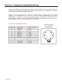
Vibrating Wire Load Cell (3, 4, 5 And 6 Gauge Cells)
User Manual
Man 188
1.0.2
06/08/2014
Chris
Rasmussen
Philip Day
Chris
Rasmussen
Manual No.
Revision
Date
Originator
Checked
Authorised for
Issue
User Manual
1
Contents
Section 1 :
Forward ......................................................................................................... 3
Section 2 :
Introduction .................................................................................................. 4
Section 3 :
Equipment Supplied & Wiring ........................................................................ 5
Section 4 :
Preparation ................................................................................................... 6
Section 5 :
Installation.................................................................................................... 7
5.01
5.02
Section 6 :
User Manual
Installation of Load Cells for Rock Bolts and Cable Anchors .................................... 7
Installation of Load Cells for Struts and Columns .................................................. 8
Calibration Certificate & Data Interpretation ................................................. 9
2
Section 1 : Forward
This instruction manual, describes the technique required for the installation of centre hole
load cells.
It is important that the materials and equipment covered by this manual should be installed by
competent and suitably qualified personnel. They must READ AND UNDERSTAND the procedures
outlined in this manual before attempting installation of the equipment on site.
Soil Instruments will not accept for repair under guarantee, instruments/materials neglected or
mishandled in any way.
The techniques described are intended to serve as a general guide and may vary to suit
particular site conditions.
User Manual
3
Section 2 : Introduction
The Vibrating Wire Hollow Load Cell (V.W.H.L.C.) has been designed for the measurement of
loads in rock bolts, single/multi-stranded anchors, structural beams, piles and between
tunnel lining segments.
The V.W.H.L.C. usually incorporates either three, four, five or six vibrating wire strain
gauges mounted parallel to the cells axis of symmetry and equally spaced. The cell is
manufactured from a high quality alloy steel, precisely machined and heat treated to provide
a stable load bearing ring.
Each vibrating wire assembly consists of a tensioned wire clamped at both ends. Located at
the mid section of the wire is a coil/magnet. If an electrical pulse is supplied to the
coil/magnet the wire will be plucked and oscillate at its natural resonant frequency. A
change in applied axial load will be proportional to the change in the square of the resonant
frequency of the wire. The coil/magnet then acts as a pickup as the oscillations of the wire
through the magnetic field induces an alternating current in the coil which can be detected
by a readout unit. The readout converts the sinusoidal alternating voltage to a square
waveform which may eaSoil Instrumentsy be timed using a frequency oscillator. In this way
the frequency of oscillation can accurately be measured.
User Manual
4
Section 3 : Equipment Supplied & Wiring
Each cell is supplied with heavy gauge multicore, PVC sheathed cable to the length specified
by the user or standard 5 metre length. Cables can be routed over distances in excess of
1000 metres without a degradation of signal.
Although cells are checked prior to leaving Soil Instruments, damage could occur during
transit. It is suggested that the cells are visually checked immediately upon receipt.
Additionally it is prudent to check the operation using a vibrating wire readout device to
ensure steady readings. If an audio signal is available on the readout device this can give a
good indication of the quality of the signal for each gauge.
The cores are identified as follows:
CHANNEL
User Manual
View From Above
Non drilled face
FUNCTION
WIRE COLOUR
A
Gauge A
Red
B
Gauge B
Black
C
Gauge C
Blue
D
Gauge D
Yellow
E
Gauge E
Violet
F
Gauge F
Grey
G
Shield
Bare
J
Thermistor
Green
K
Thermistor
White
(6 gauge cell)
C
D
B
E
A
F
5
Section 4 : Preparation
WARNING:
Do not hit or strike the cell at any time with a hammer or other object.
Base readings MUST be established on the unloaded cell prior to
installation and after loading has taken place.
To ensure instrument stability it is suggested that the load cells are monitored in a
controlled environment for as long as possible prior to installation and the readings
recorded.
Where a number of cells are to be installed it is essential that each cell and its associated
cable is accurately and effectively identified. A permanent marking system should be
adopted to ensure load cells can be identified throughout their working lifetime and this
information safely stored for future reference.
It is essential that the load bearing surfaces above and below the cell are smooth and flat,
parallel and sufficiently strong to avoid significant distortion under load. Positioning and
alignment of the cells is critical to their performance.
The surface to which the cell is to be installed should be flat and perpendicular to the
anchor. If a steel anchor plate is provided on the structure face, the area to be covered by
the cell assembly should be cleaned, in particular removing paint, smoothing out score
marks and rough imperfections with a file and abrasive paper.
Check that all the items for the installation are readily available i.e. load cell, top and
bottom bearing plates, vibrating wire readout unit, calibration data for load cell, anchor
stressing equipment and where necessary lifting equipment to support the weight of the load
cell.
The load cell serial no. and installation location should be checked and recorded.
Prior to installation, the cell should be stored close to its installation location to enable the
instrument to come into equilibrium with its temperature environment.
User Manual
6
Section 5 : Installation
5.01
Installation of Load Cells for Rock Bolts and Cable Anchors
5.1.1 Using the flying lead with crocodile clips supplied with the readout unit connect to
gauge A and record the base reading in frequency squared divided by 1000 (F 2/1000)
Repeat for gauges ‘B’, ‘C’, ‘D’, ‘E’ and ‘F’ as appropriate.
5.1.2 Carefully locate the bottom bearing plate, load cell and top loading plate over the
anchor, followed by the stressing nut and plate (for single strand anchors) or anchor
disc and collets (for multistrand anchors).Where centralising recesses or buttons are
provided on the plates, ensure that these are correctly located. Suitable lifting tackle
may be necessary in some installations to support the weight of the load cell, plates
and stressing equipment and to ensure correct alignment is maintained.
5.1.3 With the stressing equipment connected, slowly operate the hydraulic jack to provide
sufficient load to lightly hold the load cell assembly against the anchor plate. Check
for alignment and concentricity of all the components to ensure that the anchor load
is applied in line with the axis of the load cell.
5.1.4 At this stage the gauges for the cell should be read and converted to Engineering
Units. Ideally each load reading should be the same, however, in practice this is
difficult to achieve, 30% deviation between gauges is usually acceptable as the
readings are averaged to obtain axial loading. If reading deviation is within
acceptable limits record readings go to stage 6.1.6 otherwise go to stage 5.1.5.
5.1.5 If the reading deviation is not acceptable it will be necessary to de-stress the jack
and reposition the cell. If repositioning does not help all loading surfaces should be
inspected and cleaned. Repeat stage 5.1.3.
5.1.6 Loading of the anchor should be applied in increments up to the value specified by
the Engineer. Readings should be taken at each load increment to check that the load
is applied evenly through all the gauges if, at any stage, the deviation of readings
becomes unacceptable go to stage 5.1.5.
5.1.7 Prior to locking off the anchor at the required working load a number of loading
cycles should be carried out to at least the working load to check the performance of
the load cell and ensure that the anchor and load cell are correctly bedded in.
5.1.8 Most installations require the anchor to be tested to a maximum of 1.5 times the
eventual working load. The requirement for this operation should be checked and
agreed with the Engineer before the final locking off of the anchor.
5.1.9 On completion of the installation the load cell and bearing plates should be heavily
greased on all exposed surfaces.
5.1.10 The protective cover must be adequate to protect the load cell from damage as well
as differential temperature changes. Reflective external surfaces and internal
insulation will help eliminate this effect.
User Manual
7
5.02
Installation of Load Cells for Struts and Columns
5.2.1
With the temperature of the Load Cell at equilibrium connect the flylead (fitted with
clips) to the readout and to gauge A and record the base reading in Frequency
Squared divided by 1000 (F2/1000) units (see readout users manual for further
information). Repeat for gauges ‘B’, ‘C’, ‘D’, ‘E’ and ‘F’ as appropriate. These values
can now be used to set up your table parameters.
5.2.2 It is recommended that bearing plates are installed between the structural
members/reaction and the Load Cell. They will need to be positioned carefully and
where necessary fixed in place or supported. (It should be remembered that the
bearing plate includes small locating dowels to assist with centralising).Suitable
lifting tackle may be necessary in some installations to support the weight of the load
cell and plates to ensure correct alignment is maintained.
5.2.3 With the Load Cell positioned where any Axial Load Cell will be transferred, slowly
move the structural member into place and generate some pre-load. (This may be
only the weight of the column or produced by applying a load via a hydraulic jack).
5.2.4 At this stage the gauges for the cell should be read and converted into Engineering
Units. Ideally each reading should be the same, however, in practice this is difficult
to achieve, 30% deviation between gauges is usually acceptable as the readings are
averaged to obtain axial loading.
5.2.5 If the reading deviation is not acceptable it will be necessary to unload the cell
reposition it. If repositioning does not help all loading surfaces should being
inspected, cleaned and checked to confirm they are parallel. Repeat stage 5.2.3.
5.2.6 Where possible a number of loading cycles should be carried out to at least the
working load to check the performance of the load cell and ensure that the load cell
and bearing plates are correctly bedded in.
5.2.7 On completion of the installation the load cell and bearing plates should be heavily
greased on all exposed surfaces.
5.2.8 A protective cover adequate to protect the load cell from damage as well as high
differential temperature changes, should be fitted to the installation. Reflective
external surfaces and internal insulation will help eliminate this effect.
User Manual
8
Section 6 : Calibration Certificate & Data Interpretation
As with any monitoring system it is essential that all the factors that could possibly affect
the readings are recorded and taken into account such as atmospheric conditions and
construction activities. Because of the nature of the instrument, monitoring during periods of
excessive vibration will cause erroneous readings and should be avoided.
Temperature changes have a measurable effect on vibrating wire systems and therefore
ambient and differential temperatures should be recorded. It should also be remembered
that electronic systems such as readout units are known to be affected by temperature
variations.
The calibration certificate supplied with the cells is calculated with the calibration
information taken in units of Frequency Squared divided by 1000 (F2/1000). It is essential
that readings are either taken in F2/1000or converted to F2/1000 in order to apply either the
linear or polynomial factors to reduce data to load in kN. Conversion to Engineering Units
(i.e. kN) is carried out using the formulae detailed below:Linear Calibration
Load (kN) = G (R1 – R0) + K (T1 –T0)
Where:
G = Linear Gauge Factor from calibration certificate
R1 = The current reading in F2/1000
R0 = The original (base) reading in F2/1000
K = The Thermal Factor from the calibration certificate
T1 = The current thermistor reading
T1 = The original (base) thermistor reading
Polynomial Calibration
Load (kN) = AR12 + BR1 + C + K (T1 –T0)
Where:
A = The ‘A’ Polynomial Factor from the calibration certificate
B = The ‘B’ Polynomial Factor from the calibration certificate#
C = The ‘C’ Polynomial Factor from the calibration certificate
R1 = The current reading in F2/1000
K = The Thermal Factor from the calibration certificate
T1 = The current thermistor reading
T1 = The original (base) thermistor reading
User Manual
9
Bell Lane, Uckfield, East Sussex
t: +44 (0) 1825 765044
e: [email protected]
TN22 1QL United Kingdom
f: +44 (0) 1825 744398
w: www.itmsoil.com
Soil Instruments Ltd. Registered in England. Number: 07960087. Registered Office: 5th Floor, 24 Old Bond Street, London, W1S 4AW
User Manual
10