1
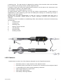
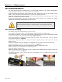
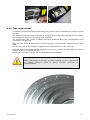
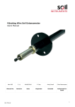
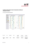
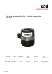
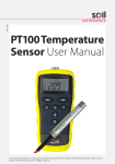
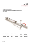
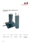
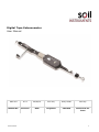
Digital Tape Extensometer User Manual Man 063 6.0.1 04/08/14 Phil Day Andy Small Phil Day Manual No. Revision Date Originator Checked Authorised for Issue User manual 1 Contents Section 1 : 1.01 1.02 1.03 1.04 1.05 Section 2 : 2.01 2.02 2.03 2.04 Section 3 : 3.01 Section 4 : 4.01 4.02 4.03 Section 5 : User manual Introduction .................................................................................................................................3 Important information .................................................................................................................. 3 Taking care of your Tape Extensometer ................................................................................... 3 System components...................................................................................................................... 4 Familiarisation ................................................................................................................................ 4 Features ........................................................................................................................................... 5 Basic Operation...........................................................................................................................6 Turning on ....................................................................................................................................... 6 Checking the zero reading ........................................................................................................... 6 Reading reference points ............................................................................................................. 6 Turning off....................................................................................................................................... 8 Temperature correction ..........................................................................................................9 Correcting for temperature changes ......................................................................................... 9 Maintenance ...............................................................................................................................10 Routine Maintenance .................................................................................................................. 10 Battery Changing ......................................................................................................................... 10 Tape replacement ........................................................................................................................ 11 Help and Support .....................................................................................................................12 2 Section 1 : Introduction 1.01 Important information Thank you for choosing the Itmsoil Tape Extensometer. This manual has been written to help you operate and maintain the Tape Extensometer. Please read this manual thoroughly before use and keep it handy when using the Tape Extensometer. The following symbols are used throughout the manual: This Symbol indicates a warning. Failure to observe the warning may result in injury, product malfunction, unexpected readings or damage to the product that may invalidate its warranty. This symbol indicates a tip. Additional information that may be helpful when using the Tape Extensometer. Soil Instruments has an ongoing policy of design review and reserves the right to amend the design of the Tape Extensometer and this instruction manual without notice. Please refer to our terms and conditions of sale for warranty information. The battery is a considered a consumable item and is only warranted for a period of 6 Months. Only use the correct battery type as supplied fitted to this Tape Extensometer. Using incorrect battery types may damage the digital display. Products marked with the European countries. symbol are subject to the following disposal rules in This product is designated for separate collection at an appropriate collection point Do not dispose of as household waste For more information, contact Itmsoil Ltd or the local authorities in charge of waste management 1.02 Taking care of your Tape Extensometer Soil Instruments Tape Extensometer has been designed for use in harsh environments however certain precautions should be observed to ensure a long reliable product life. Do not drop The Tape Extensometer may malfunction if subjected to strong shocks or vibrations. User manual 3 Do not immerse or expose to water jets The Tape Extensometer has been designed to be used in a dry environment and may malfunction if immersed under water or used in a wet environment. Keep away from strong magnetic fields Do not use or store this device in the vicinity of equipment that generates strong electromagnetic radiation or magnetic fields. Avoid extremes of temperature Do not expose to extreme heat or cold temperatures as this may cause damage to the Tape Extensometer. 1.03 System components In addition to this manual you should have: Tape Extensometer unit Battery change screw driver Carry Case Tape Extensometer unit Carry Case Battery change screw driver 1.04 Familiarisation The Tape Extensometer unit comprises a stainless steel measuring tape with equally spaced precision punched holes. The fixed end of the tape is fitted to the tape reel integral with the lightweight body, which has a reference point-locating hook identical to that on the free end of the tape. The body incorporates a tape-tensioning device coupled to a sliding scale and digital gauge arrangement. The location pin is engaged into the appropriate tape hole and is secured with User manual 4 a retaining clip. The tape tension is adjusted by rotation of the knurled collar until the black line is centred in the spring tension window alignment slot. A reading is taken by noting the located pinhole position on the tape at the instrument nose and adding the reading on the digital scale. The resolution of the digital gauge is 0.01mm. As measurements taken in this way can only be relative measurements, a base reading is established for each measuring point and all subsequent readings are measuring change in relation to the base reading. If more than one tape extensometer is used on a site it is advisable that each unit is dedicated to particular reading points to ensure maximum accuracy and continuity of readings. A reference frame is available for establishing offset values between units and for determining unit accuracy. 1. Location Hook 2. Location Pin 3. Retaining Clip 4. Spring Tension Window 5. View Window 6. Knurled Collar 7. Winding Handle 7 6 5 4 3 1 2 1.05 Features Listed below is a short list of the features designed into the Tape Extensometer. User manual Automatic power on upon rotation of the adjuster barrel Automatic power down after 20 minutes of no movement of the adjuster barrel 3 years battery life under normal operating conditions Light weight body and components. High quality digital gauge Low battery warning indicator 5 Section 2 : Basic Operation This section will describe the basic functionality and operations required to read reference points. 2.01 Turning on To switch on the Tape Extensometer unscrew the adjusting barrel a few turns, the digital display will turn on. Only rotate the adjuster barrel while holding the body of the Tape Extensometer. Rotating the adjuster barrel whilst holding the winding frame may cause damage to the internal components. The digital gauge has an automatic power down function which shuts off the display after 20 minutes of no change in reading. 2.02 Checking the zero reading Rotate the adjuster barrel back in to its closed position and check that the digital display shows 0.00mm. Temperature changes to the body and internal components may result in the zero reading being incorrect by +/- 0.02mm. This error is insignificant in relation the instrument repeatability and should be regarded as an acceptable zero error. If the zero value needs to be reset remove the front panel by extracting the 4 securing screws and then hold down the blue “Origin” button for more than 1 second. Replace the front panel and the 4 securing screws. 2.03 Reading reference points Unscrew the adjuster barrel until 28mm is displayed on the digital gauge. The adjuster barrel has an internal limiter to prevent the adjuster barrel being unscrewed too far. Do not force the adjuster barrel beyond the limiter as this will damage the digital gauge. Attach the locating hook on the free end of the tape to one of the reference points to be measured. Unwind sufficient tape and locate the hook on the end of the winding frame to the other reference point. Using the winding handle of the tape reel, take up the slack in the tape. User manual 6 Unclip the tape retaining clip on the nose of the extensometer and engage the location pin through the nearest accessible punched hole in the tape. With the pin engaged, slide the retaining clip over the tape and back into position. Adjust the knurled collar inwards until the tape becomes under tension. Ensure the tape is not twisted over it tensioned length, rotate the extensometer to ensure the tape is not twisted. Continue to wind the collar inwards until the black line on the internal spring anchor block is centred in the spring tension window alignment slot with no visible yellow either side of the black line. During this operation, the Tape Extensometer should be physically moved either side of the median position to ensure that any hysteresis within the instrument is eliminated. The correct tension is obtained when there are no visible yellow on either side of the black cursor line, and when any slight displacement to the extensometer reads as a positive displacement of the cursor line. Over tensioning the Extensometer can result in elongated or torn punched tape holes. Record the displayed reading and the tape hole position for the set of reference points. The total reading value is the tape hole position added to the reading from the digital gauge e.g. 2125mm add 2.10mm = 2127.1mm. Where: The tape hole position is 2125mm The reading from the digital gauge is 2.10mm Unscrew the adjuster barrel and unclip and remove the tape from the location pin. Unhook the Extensometer and the tape from the reference points and wind the tape back onto the reel. The extensometer is now ready for the next set of reference points. User manual 7 2.04 Turning off The Extensometer will auto turn off after 20 minuets of no movement of the adjuster barrel. There is no manual operation to turn the unit off. User manual 8 Section 3 : Temperature correction 3.01 Correcting for temperature changes The coefficient of linear expansion of the stainless steel tape is 0.0000116m per m per °C. The instrument itself can be corrected for temperature by applying the following correction: 8.33 x 10⁻⁶ metres per Dec C. Hence a temperature correction for 'n' metres of tape used for T temperature change is:For steel tape = n(0.0000116m per °C)T + (8.33 x 10⁻⁶)T User manual 9 Section 4 : Maintenance 4.01 Routine Maintenance The Tape Extensometer is designed for dry environment field work, but routine maintenance is still needed to maintain the best condition and reliability. Clean the Tape Extensometer with a clean soft cloth; ensure the cloth is not engrained with sand or other abrasive materials that may scratch the display window. Keep the Extensometer clean and dry and occasionally lubricate moving parts with a light machine oil, wipe off excess oil residue. should the extensometer become wet and suffer water ingress then remove the display window and allow the Extensometer to fully dry out. Do not use any solvents or cleaning agents on the display window. 4.02 Battery Changing The battery will give approximately 3 years of use. A low battery warning symbol will be displayed when the battery is getting low. To replace the battery, first remove the display window and then remove the battery access screw on the base of the extensometer body – Figure A & B Using the supplied screwdriver insert through the access hole and locate into the battery cover retaining screw – Figure C Unscrew the screw by three full rotations and then push gently on the screw to lift the battery cover. Unscrew by another two full rotations and withdraw the screw through the access hole. Remove the battery cover and remove the battery – Figure D Replace the battery with the correct replacement (Silver oxide SR44 1.5V) Refit the battery cover and the cover retaining screw Refit the battery access screw. With the Adjuster barrel in the fully wound in position hold down the blue “origin” button for more than one second – Figure E The display will reset to 0.00 check that “mm” is displayed, if “in” is displayed then press the “in/mm” button. A User manual B C 10 D E 4.03 Tape replacement Completely unwind the tape and disengage the end loop from its attachment lug and remove the tape. File off the rivet heads of the end bracket fixing of the old tape and separate the two halves, thus freeing the shaft of the locating hook assembly. The replacement tape comes complete with fixing brackets, shim and corresponding holes punched in the tape end. Place the half of the bracket with the two rivet lugs on a flat surface followed by the shim plate. Lay the tape end on the bracket, engaging the punched holes over the rivet lugs. Place the shaft of the locating hook assembly in the groove and fit the other half of the fixing bracket to secure the shaft and tape. Punch the rivet lugs to secure the two brackets securely together. After replacement of the tape new base readings must be established on existing reference points to ensure accurate continuity of measurements’. User manual 11 Section 5 : Help and Support Product Support is available at www.itmsoilsupport.com Bell Lane, Uckfield, East Sussex t: +44 (0) 1825 765044 e: [email protected] TN22 1QL United Kingdom f: +44 (0) 1825 744398 w: www.itmsoil.com Soil Instruments Ltd. Registered in England. Number: 07960087. Registered Office: 5th Floor, 24 Old Bond Street, London, W1S 4AW User manual 12