1
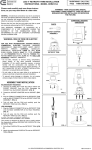
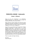
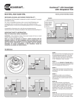
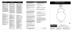
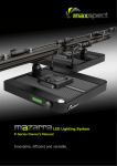
NOTE 1: Line Voltage Dimming of TROPO Drivers
ROAL RLDD TROPO Series User Manual
Introduction
This application note will address the different types of line voltage dimmers which are
compatible with the TROPO series of LED drivers.
Dimmers are available in several basic types from many manufacturers around the world.
TROPO drivers have been designed to operate with most standard dimmer switches designed for
incandescent lighting as well as other types of lighting.
This application note does not discuss methods of dimming, such as 0-10V, which do not apply
to Tropo drivers.
Be certain the application and installation complies with the dimmer manufacturer’s installation
guidelines as well as all local, state and federal laws, requirements and codes. Wire the dimmer
to the Tropo driver in accordance with the dimmer manufacturers installation requirements,
connecting the driver in place of the lighting fixture with the LED connected to the output of the
driver.
NOTE: Tropo LED drivers incorporates linear dimming technology (not PWM
technology). As a result, each application must be carefully evaluated to ensure it
meets the specifications of the end product and the specific LED.
Basic Dimmer Application
A line voltage dimmer is a device that connects between the AC power source and the lighting
fixture. For LED lighting with a Tropo driver, the dimmer is connected to the input source of the
driver and the LED is connected to the output of the driver. The dimmer chops the AC voltage
and the driver reacts to this by adjusting the output current supplied to the LED.
Figure 1 depicts a simple application of the TROPO LED driver.
Triac
Based
Dimmer
TROPO
FIGURE 1
The period of the AC cycle during which power is applied to the driver is referred to as the
conduction time. This is measured in degrees of a half AC cycle or time (typically ms). A full
period would be 180 degrees or 8.3ms for 60Hz and 10ms for 50Hz. This application note uses
the conduction time in reference to this period.
TRC ELECTRONICS, INC.
1.888.612.9514
www.trcelectronics.com/roal
NOTE 1: Line Voltage Dimming of TROPO Drivers
ROAL RLDD TROPO Series User Manual
Triac Based Dimmers
The most common type of dimmer in use for residential applications is better known as a triac
based dimmer. These are also the simplest types of dimmers, and in general, the least
expensive. A triac based dimmer may also be referred to as a Forward Phase-Control or Leading
Edge dimmer. A triac is used as the power switching element in the dimmer. Due to the nature
of the triac, the dimmer does not apply power to the controlled device (driver) until sometime
after the zero crossing of the AC cycle. Once the dimmer starts conducting, it will do so until the
zero crossing of the AC cycle. Dimming is achieved by delaying the time at which the dimmer
starts to conduct. As the dimmer is moved through its range, the amount of time that the AC
voltage is applied varies.
Figure 2 shows the relationship of the AC input voltage versus the output of a triac based dimmer.
Forward Phase-Control (Leading Edge)
Chopped AC Input to Driver
AC Wall Power
0
50
100
150
200
250
300
350
400
Conduction (Degrees)
Figure 2
A triac based dimmer is typically a simple 2 wire device that is connected as a switch. This means
the second line of the AC power is not required to be connected to the dimmer.
TRC ELECTRONICS, INC.
1.888.612.9514
www.trcelectronics.com/roal
NOTE 1: Line Voltage Dimming of TROPO Drivers
ROAL RLDD TROPO Series User Manual
Electronic Low Voltage (ELV) Dimmers
ELV dimmers are typically more expensive than triac based dimmers. These dimmers use more
elaborate circuitry to control the output voltage. ELV dimmers are available in both Forward
Phase-Control (Leading Edge) and Reverse Phase-Control or Trailing Edge types. A Reverse
Phase-Control dimmer will start to provide power to the load at the zero crossing of the AC cycle
and terminate somewhere during the cycle. Dimming is achieved by delaying the time at which
the dimmer stops conducting.
Figure 3 shows the relationship of the AC input voltage versus the output of a Reverse PhaseControl dimmer.
Reverse Phase-Control (Trailing Edge)
Chopped AC Input to Driver
AC Wall Power
0
50
100
150
200
250
300
350
400
Conduction (degrees)
FIGURE 3
ELV dimmers require power to operate. This means that the dimmer must be wired to both sides
of the AC input voltage.
TRC ELECTRONICS, INC.
1.888.612.9514
www.trcelectronics.com/roal
NOTE 1: Line Voltage Dimming of TROPO Drivers
ROAL RLDD TROPO Series User Manual
Dimmer Considerations
There are a few considerations for line voltage dimmers. All triac based dimmers have a
minimum operating power level, typically around 40W. With incandescent bulbs, meeting this
minimum power requirement was never a concern. However, with LED lighting, multiple
drivers/fixtures may have to be connected to a single triac based dimmer in order to meet this
requirement. In most applications, a single TROPO will operate properly when connected to a
single dimmer, but this cannot be guaranteed due to the variability and characteristics of the
dimmer.
Each application should be carefully reviewed to ensure that the minimum power level of the
dimmer is achieved. If the application consumes less power than the minimum dimmer rating, a
different dimmer should be chosen or perhaps an ELV dimmer which does not suffer from this
limitation.
Another consideration that applies to all dimmers is the dimming range. The dimming range
varies greatly from manufacturer to manufacturer and sometimes from lot to lot of dimmers.
Some dimmers will operate over a very wide range while others are very small. In some cases
the minimum amount of conduction time will not permit the driver to reduce the output to 10%
of nominal current. Similarly, the maximum amount of conduction time of some dimmers may
result in the output of the driver to be less than the full rated current. However, Tropo has been
designed to operate with most dimmers and operation should be very similar to what would be
expected with an incandescent bulb.
TROPO has been designed to operate with most standard line voltage dimmers of all types.
Operational characteristics are greatly affected by the dimmer chosen.
Due to the nature of the triac dimmer being a very uncontrolled (specifications vary significantly), the
end product that uses the Tropo driver must be carefully evaluated to ensure it is compliant with the
end products requirements and customer expectations.
TRC ELECTRONICS, INC.
1.888.612.9514
www.trcelectronics.com/roal
NOTE 1: Line Voltage Dimming of TROPO Drivers
ROAL RLDD TROPO Series User Manual
TROPO Dimming Specifications
TROPO is designed to dim down to 10% of the nominal output current. In order to achieve this, the
dimmer must be capable of reducing the conduction angle down to approximately 30 degrees. To achieve
full output current from the driver, the dimmer must be capable of achieving a conduction angle of at
least 150 degrees.
Figure 4 shows the output characteristics of a typical TROPO model comparing the output current versus
the conduction angle at various input voltages.
Typical Io vs Conduction Angle
Output Current (A) Normalized to I Set
1.2
1
100V (200V)
0.8
115V (230V)
132V (264V)
0.6
0.4
0.2
0
0
20
40
60
80
100
120
140
160
VAC Conduction Angle (Degrees)
FIGURE 4
In order to obtain the optimum dimming performance from the TROPO driver, ensure the dimmer and
application are compatible, refer to dimmer considerations for details. Failure to meet the minimum load
requirements may result in poor dimming performance or flicker, especially at low dimming levels.
TRC ELECTRONICS, INC.
1.888.612.9514
www.trcelectronics.com/roal
NOTE 1: Line Voltage Dimming of TROPO Drivers
ROAL RLDD TROPO Series User Manual
Suggested Dimmers
TROPO drivers are designed to operate with most standard dimmers. However, ROAL has performed
extensive testing with the dimmers listed below. This list of dimmers does not imply any guarantee or
warranty of compatibility with a particular application. The lack of dimmers on this list does not imply it is
not compatible with TROPO drivers.
Cooper, Aspire Series (Part numbers 9530XXX)
Leviton, Illumitech Series (Part numbers IPI06-XXX)
Leviton, Trimatron Series (Part numbers 6602-X, 6681-X, 6683-X, 6684-X, 700-X and 705-X)
Leviton, SureSlide Series (Part Numbers 6631)
Leviton, True Touch Series (Part Number 6606-1LM)
Lutron Skylark Series (Part Number S-600, S2-LH)
In addition, the following Electronic Low Voltage (ELV) dimmers that employ reverse phase control have
been tested with TROPO:
Lutron Nova T Series (Part number NTELV-600)
Lutron Faedra (Part Number FAELV-500-XX)
Leviton Acenti (Part Number ACE06-XXX)
Leviton Vizia (Part Number VZE04)
While the above dimmers have been tested by Roal, the performance varies greatly. Some dimmers are
not capable of meeting the wide conduction angles that Tropo can support. As a result, reduced range of
dimming may occur.
Digital dimmers, such as the Lutron Maestro are not supported by TROPO. Damage will not occur to the
dimmer or the TROPO driver, but proper performance is not possible with these dimmers.
Roal has tested the dimmers with Tropo over a wide variety of system configurations. However, due to
the high degree of variability when dimming, all applications of TROPO should be evaluated prior to
product release to ensure the end product meets expectations. When the installation exceeds 10 fixtures
on a single dimmer or distribution lengths exceed 100 feet, extra care must be taken to ensure the end
product performs properly. This is a result of the high degree of variability in the triac dimmers.
Although Roal has performed extensive testing on TROPO, the number of system variables is significant.
Therefore, operations in every conceivable system application cannot be guaranteed.
TRC ELECTRONICS, INC.
1.888.612.9514
www.trcelectronics.com/roal
NOTE 1: Line Voltage Dimming of TROPO Drivers
ROAL RLDD TROPO Series User Manual
Troubleshooting of dimming problems
Problem
LED does not achieve full light
output at high end of dimming
range
LED is always at full brightness,
does not dim
When the dimmer is turned to
minimum and the power applied,
the LED doesn’t turn on until the
dimmer level is raised.
Possible Cause
• Dimmer maximum conduction
angle <150 degrees
• Low AC Input voltage
• Incorrect Tropo driver for LED in
use
• Faulty dimmer
• Faulty driver / LED
• Dimmer wired incorrectly
• Faulty dimmer
• This is typical operation for
dimmers that reduce to a
conduction angle of less than
approximately 20 degrees. The
Tropo driver will operate at this
very low conduction angle, but
may have difficulty starting up
in this condition.
When the dimmer level is raised
very fast, the light output appears
to reach a level and than reduce
slightly.
•
LED dims, but does not low enough
•
LED flickers (not when dimming)
•
Driver / LED is less than the
minimum rating of the dimmer
•
Poor electrical connections
TRC ELECTRONICS, INC.
1.888.612.9514
Under some conditions (load,
line, LED voltage etc), the
output circuit of Tropo may
overshoot slightly when rapidly
adjusting the dimming. Typically
this occurs when the output
power is less than the rating of
the driver and only when the
dimmer is changed rapidly.
Dimmer minimum conduction
angle is >30 degrees
Solution
• Change dimmer to a device that
dims to >150 degrees
• Correct low AC voltage
• Call Roal Electronics to discuss
the application
• Replace dimmer
• Replace driver / LED
• Check and correct wiring
• Replace dimmer
• If the dimmer includes a low end
adjustment, raise the dimming
level.
• Suggest operation should include
turning up and than down to set
the desired setting.
• Replace with a dimmer with low
end adjustment and set
accordingly.
• If the condition is sever, contact
Roal to discuss the application.
• If the dimmer is equipped with a
low end adjustment, lower the
minimum angle
• Change dimmer to a device that
dims to <30 degrees
• Change the dimmer to an ELV
type
• Connect additional fixtures to the
dimmer circuit to satisfy the
dimmer minimum load rating
• Check and correct any poor
connections
www.trcelectronics.com/roal
NOTE 2: Drivers Output Voltage Range
ROAL RLDD TROPO Series User Manual
Introduction
This application note has been written to assist with selection of ROAL Tropo Series drivers. Since
there are many configurations of LED designs, care must be taken to ensure that the operation
window for the Tropo series is not violated. It is apparent that when the input of Tropo is dimmed
with a line voltage dimmer, the output current is adjusted. As the output current reduces, so does
the forward voltage of the LED(s) connected to the output. Care must be taken when selecting a
Tropo driver to ensure the output voltage is always within the operating voltage range. This includes
when being dimmed.
This application note will address the operation of Tropo drivers with respect to the output voltage
operation range.
It is suggested to review Roal Tropo Application Note # 1, Line Voltage Dimming of Tropo Drivers,
prior to this application note.
Tropo Output Voltage Range
Tropo drivers include 28 standard models. The output of the driver is constant current regulated to a
factory set point. The drivers also have a specified output voltage operating range that must be met
under all conditions, including when being dimmed. Figure 1 is a table that summarizes the models,
the output current setpoint and the operating voltage range for each model. This range is identical
for 120VAC and 240VAC drivers.
Model Number
(X = H or L)
RLDD015X-350
RLDD015X-350H
RLDD015X-350J
RLDD015X-480
RLDD015X-600
RLDD015X-700
RLDD015X-800
RLDD015X-900
RLDD015X-900L
RLDD015X-1000
RLDD015X-1200
RLDD015X-1250
RLDD015X-1400
RLDD015X-1500
Vout Min*
(vdc)
24
12
18
10
8
16
8
10
8
10
10
8
8
5
Vout Max*
(vdc)
48
21
32
13.5
12
24
12
16
12
16
13.4
12
11.5
10
Iout Set
(mA)
350
350
350
480
600
700
800
900
900
1000
1200
1250
1400
1500
FIGURE 1
The Vout Min and Vout Max must be met under all conditions of the driver and LED assembly,
including when being dimmed and when the fixture is at maximum operating temperature.
Failure to meet this requirement may result in poor performance of the end product. Typically this will result
in some flicker at the low end of the dimming range. The Tropo driver and LED will not be damaged under a
low output voltage condition.
TRC ELECTRONICS, INC.
1.888.612.9514
www.trcelectronics.com/roal
NOTE 2: Drivers Output Voltage Range
ROAL RLDD TROPO Series User Manual
LED Voltage rating
Unfortunately, most LED manufacturers do not provide detailed information regarding the forward voltage at
reduced currents and temperatures other then 25C. Therefore, laboratory measurements and calculations
should be made to ensure the minimum voltage is maintained under all anticipated operating conditions.
Typical number of LEDs supported
Each standard Tropo model will perform with a certain number of LEDs in a string. The following table
summarizes this data. This is based on a broad range of standard individual LEDs from various
manufacturers. This list does not imply Tropo will operate properly with the indicated number of LEDs
under all conceivable operating parameters and from every LED manufacturer, but should serve as a
guide in determining the Tropo driver possible for a particular application.
Model Number
RLDD015X-350
RLDD015X-350H
RLDD015X-350J
RLDD015X-480
RLDD015X-600
RLDD015X-700
RLDD015X-800
RLDD015X-900
RLDD015X-900L
RLDD015X-1000
RLDD015X-1200
RLDD015X-1250
RLDD015X-1400
RLDD015X-1500
Vout Min*
(vdc)
24
12
18
10
8
16
8
10
8
10
10
8
8
5
Vout Max*
(vdc)
48
21
32
13.5
12
24
12
16
12
16
13.4
12
11.5
10
Iout Set
(mA)
350
350
350
480
600
700
800
900
900
1000
1200
1250
1400
1500
Suggested # of
LEDs in a string
10 to 13
4 to 6
7 to 9
3
3
4 to 6
3
4
3
4
4
3
3
2
FIGURE 2
If an application does not meet the above requirements, contact Roal to discuss a modified standard product.
It is possible to modify the Tropo driver to operate at lower currents to permit a wide variety of possible
driver models.
In addition, if the application will utilize an LED chip assembly, consult the factory for possible drivers for the
application. There are a number of drivers already designed to operate with Bridgelux and Citizen LED chip
assemblies.
NOTE: SOME STANDARD MODELS ARE BUILT TO ORDER. PLEASE CONSULT THE FACTORY TO
CHECK AVAILABILITY.
TRC ELECTRONICS, INC.
1.888.612.9514
www.trcelectronics.com/roal
NOTE 2: Drivers Output Voltage Range
ROAL RLDD TROPO Series User Manual
TRC ELECTRONICS, INC.
1.888.612.9514
www.trcelectronics.com/roal
NOTE 3: Mounting Clip Instructions
ROAL RLDD TROPO Series User Manual
Introduction
The Tropo series of LED drivers is equipped with a Universal Mounting
Clip design. The customer can decide which of the six available mounting
locations are most suitable for the particular application and install the
mounting feet at the time of installation.
The Tropo driver is shipped from the factory with 2 clips which should be
suitable for most installations. If additional or replacement clips are
required, please contact ROAL Electronics.
Prior to installation of the mounting clips, determine which of the six
locations to attach the clips to.
Clip Installation
1. Position the 2
small feet of the clip
into the indentations
on the bottom of the
driver.
3. With a finger at
the base of the clip,
apply gentle
pressure upward on
the clip.
2. Rotate the
upper part of the
clip up towards
the larger
indentation on the
top of the driver.
4. Until the clip
snaps into place.
Clip Removal
To remove the clip, use a small
pair of pliers on the mounting clip
flange and twist away from you.
This will disengage the feet from
the case and free the clip.
Be careful not to apply excessive
outward force as this may damage
the driver plastic case material.
TRC ELECTRONICS, INC.
1.888.612.9514
www.trcelectronics.com/roal