1
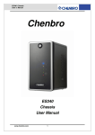
ES34169 Chassis User’s Manual Rev. A1 Chenbro ES34169 Chassis User Manual April / 2 / 2010 www.chenbro.com 1 ES34169 Chassis User’s Manual Rev. A1 Copyright Copyright © 2007 Chenbro Micom Co., Ltd.. All rights reserved. Unless otherwise indicated, all materials in this manual are copyrighted by Chenbro Micom Co., Ltd.. All rights reserved. No part of this manual, either text or image may be used for any purpose other than internal use within purchasing company. Therefore, reproduction, modification in any form or by any means, electronic, mechanical or otherwise, for reasons other than internal use, is strictly prohibited without prior written permission. Chenbro Micom Co., Ltd. reserves the right to make improvement and modification to the products indicated in this manual at any time. Specifications are therefore subject to change without prior notice. Information provided in this manual is intended to be accurate and reliable. However, Chenbro Micom Co., Ltd., assumes no responsibility for its use, nor for any infringements upon the rights of third parties, which may result from its use. Technical Support Chenbro works hard to offer our customers maximum performance from our chassis. But in case you have any problem with our product you can find supports from the following resources. Web Support Detail information of our products is in our website. You can find technical updates, installation guides, FAQs, Technical specifications and more. Our web address is: www.chenbro.com. Email Support You can also fill out the technical support form at our Technical Support page. Your technical issue inquiries will be sent directly to our support professionals. Phone Support You can also contact Chenbro HQ or branch office for immediate support; contact Information is as following: Chenbro HQ Chenbro Europe B.V. Chenbro Micom (USA) Inc. Tel: 886-2-8226-5500 Tel: 31-40-295-2045 Tel: 1-909-947-3200 Fax: 886-2-8226-5423 Fax: 31-40-295-2044 Fax : 1-909-947-4300 www.chenbro.com 2 ES34169 Chassis User’s Manual Rev. A1 Content Packing List ................................................................................................................4 ES34169 Chassis...............................................................................................4 Optional Items....................................................................................................4 Features.......................................................................................................................5 Technical Specifications .........................................................................................5 Opening the Chassis................................................................................................6 Side Panel Removal..........................................................................................7 Front Bezel Removal ........................................................................................7 Motherboard Cage Removal ..........................................................................8 Devices Installation ..................................................................................................9 Installing Slim Optical Drive (Slim ODD) ....................................................9 Installing 3.5” SATA-II Hard Drive ...............................................................10 Installing Card Reader ...................................................................................10 Installing Riser Card.......................................................................................12 Installing 2.5” HDD..........................................................................................13 Connecting Devices ...............................................................................................13 Connecting SATA-II Cables ..........................................................................13 Connecting Power Cables ............................................................................14 Connecting Front Panel I/O, LED and Slim ODD Cables......................14 a. USB 2.0 cable connection ................................................................14 b. Front display cable connection ......................................................15 c. Slim ODD cable connection.............................................................15 d. Cable management ............................................................................15 Power Supply ...........................................................................................................16 Specification: ...................................................................................................16 Protection: ........................................................................................................16 Environmental Requirements:.....................................................................16 Mechanical Dimension: .................................................................................16 2-port SATA-II Backplane ......................................................................................17 Hardware Specification: ................................................................................17 Backplane Connectors ..................................................................................17 www.chenbro.com 3 ES34169 Chassis User’s Manual Rev. A1 Packing List ES34169 Chassis Item Q’ty Chassis 1 3.5” HDD tray 4 2-port SAS / SATA-II backplane 2 70x15 mm rear fan 2 SATA-II cable, 440 mm 4 120 watts internal PSU 1 Screw pack for motherboard 1 Screw pack for HDD 1 USB 2.0 cable 1 Key, front door 1 Remark Optional Items Item Part # Power Cord, Europe 34H032100-011 Power Cord, USA Japan 34H013100-013 Power Cord, Australia 34H023100-006 Power Cord, UK 34H043100-005 Heatsink, for AMD / intel Socket 66H084534-001 Riser Card, PCI 32-bit 80H094340-001 4-in-1 card reader 83H554534-002 4-in-1 card reader bracket 83H554534-004 Slim ODD adapter, IDE 84H453410-021 Slim ODD adapter, SATA 84H453410-022 60x15 mm fan 30H060015-103 www.chenbro.com 4 Remark Special size = 45mm SD / Mini-SD / MMC / MCS ES34169 Chassis User’s Manual Rev. A1 Features z 120 watts internal power supply z Ideal for high storage capacity (Hot-swap HDDs) with RAID-5 functionality z Available for multi-media platform z 9.5 liters small form factor with Mini-ITX M/B z Removable M/B carrier for excellent thermal performance & easy cabling z External adapter reduces noise level z Optional remote control & riser card Technical Specifications Model Name ◆ES34169 M/B Form Factor ◆Mini-ITX Dimension (DxWxH) ◆260mm x140mm x260mm ◆Hot-swap: 3.5" x4 Drive Bay ◆10.24" x 5.51" x 10.24" ◆Internal: 2.5" x1 (optional) ◆Slim ODD: 1 (optional) PSU ◆Form Factor: External Adapter 120 W Indicator LEDs ◆Power, HDD Activity, LAN x2, Fault Front Control ◆Power, Reset & Alarm Mute Switches Front Access ◆USB 2.0 x2 Security ◆Kensington Lock & Padlock Loop Cooling Fan ◆Front: 60mm (optional) Slot Opening ◆Low Profile x1 Material ◆SECC Plastic Material Type ◆ABS-HB Sheet Metal Thickness ◆0.7 mm Net Weight ◆4.9 Kgs Gross Weight ◆5.9 Kgs Backplane ◆SATA-II / SAS Container Info. www.chenbro.com ◆SD/Mini-SD/MMC/MS Card Reader (optional) ◆Single Packing 5 ◆Rear: 70x15mm x2 20' 40' 40'H 672 1344 1512 ES34169 Chassis User’s Manual Rev. A1 Opening the Chassis Overview Side Panel w/Venting Slim CD-ROM Carrier (Optional) Main Cable through hole w/ rubber pad Front Bezel (w/Key Lock) Intrusion switch USB & front Control cables Motherboard cage Front Card Reader (Optional) Slim ODD Cover USB 2.0 ports x2 Front Control Display: Power Status LED (Blue) HDD Access LED (Amber) LAN#1 Activities LED (Green) LAN#2 Activities LED (Green) Global Failure LED (Red) 4x 3.5” HDD Carrier Front Control Switches: Power On Switch System Reset Alarm Mute Back LED VCC & recovery switch (optional) Low profile Slot opening Pad Lock Rear 70mm fans (x2) Kensington lock Side Panel Screw Power connector www.chenbro.com 6 ES34169 Chassis User’s Manual Rev. A1 To open the chassis for assembly of internal parts, users need to: z Remove the side panel and front bezel Side Panel Removal 1 2 ■ Release the side panel thumb screw on the rear ■ Push and slide the side panel toward rear to open the chassis Front Bezel Removal 1 2 ■ Lift up the latch along the side to detach the bezel ■ Detach the bezel from Slim ODD side gently 3 4 ■ gently pull the bezel to make it detach ■ Angle the latch until it is 15 degree away from the chassis www.chenbro.com 7 ES34169 Chassis User’s Manual Rev. A1 Motherboard Cage Removal 1 2 ■ Release 6 secure screws on the M/B cage ■ Remove the motherboard cage 3 4 ■ Detach the motherboard cage with System Cables (SATA, Power, Fan cables) through the cable routing hole ■ Disconnect the extension fan cables 5 ■ Finish detaching the M/B cage and make sure all the connection on backplane and PDB are still tight before assembly back the M/B cage www.chenbro.com 8 ES34169 Chassis User’s Manual Rev. A1 Devices Installation Optional Parts: z Slim Optical Drive z 3.5” HDD z 4-in-1 Card Reader z Riser Card z 2.5” HDD Installing Slim Optical Drive (Slim ODD) Before install the slim ODD, the front bezel must be removed. The slim ODD carrier should be apart from the chassis. 1 2 ■ Assemble the adapter board with attached screws onto Slim ODD ■ Make sure the Slim ODD is fully seated with holder clip on the side. 3 4 ■ Slide the assembled ODD into chassis ■ Make sure the holder latch is secured when fully seated www.chenbro.com 9 ES34169 Chassis User’s Manual Rev. A1 Installing 3.5” SATA-II Hard Drive 1 2 ■ Remove the HDD Carrier from the chassis and place the SATA-II HDD into it. ■ Attach the HDD screws on both sides 3 4 ■ Make sure the carrier is fully seated ■ Slide in the assembled HDD into the chassis, suggest install by the ID definition on the front panel (No need to remove the front bezel) Installing Card Reader 1 2 ■ Detach the front screw of Card Reader holder ■ Pull out the Card Reader holder www.chenbro.com 10 ES34169 Chassis User’s Manual Rev. A1 3 4 ■ Remove the seal on the holder and make sure the sockets is right to the opening ■ Attach screws to fix the Card Reader 5 6 ■ Connect the short end of USB split cable to Card Reader ■ Install the assembled Card Reader back to the chassis with screw 7 ■ connect cable to USB port on M/B www.chenbro.com 11 ES34169 Chassis User’s Manual Rev. A1 Installing Riser Card 1 2 ■ Remove the cap on slot holder ■ Detach the low profile slot bracket from rear window 3 4 ■ Assemble riser and low profile add-on card ■ Connect the cables before install. 5 6 ■ Install the riser card onto motherboard. (Please pay attention to the cable arrangement) ■ Attach screws on the rear side to secure the PCI card www.chenbro.com 12 ES34169 Chassis User’s Manual Rev. A1 Installing 2.5” HDD 1 2 ■ Place 2.5” HDD underneath the Slim ODD ■ Fix the 2.5” HDD with attached screws Note: To install 2.5” HDD, disassemble the M/B cage is required. Connecting Devices z Four SATA-II cables for Hot-swap hard drive (HDD) z Power cables for M/B z Front panel I/O cables z USB 2.0 cable Connecting SATA-II Cables 1 2 ■ Check the bundled cable with number tag ■ Connect the SATA cables to the M/B properly Note: If there is no enough SATA port on M/B, users can either remove or keep the bundled P3/P4 SATA cable. www.chenbro.com 13 ES34169 Chassis User’s Manual Rev. A1 Connecting Power Cables 1 2 ■ The DC harness comes with 20+4 pin as main connection for different M/B requirement. ■ Install and secure the DC harness cable to the M/B properly Connecting Front Panel I/O, LED and Slim ODD Cables a. USB 2.0 cable connection 1 ■ Front USB cable should be connected to on-board USB header properly depends on different M/B. www.chenbro.com 14 ES34169 Chassis User’s Manual Rev. A1 b. Front display cable connection 1 2 ■ The cable with different connection for: Power on, HDD, LAN, FAIL and the front switch ■ Connect to the M/B according to the M/B pin header definition properly. c. Slim ODD cable connection 1 2 ■ Use power split cable in accessory pack for conversion ■ Use either standard IDE / SATA cable from 3rd party of DC harness, small 4P is connected to the Slim ODD adaptor board M/B, or use optional cable from Chenbro to connect to the Slim ODD adaptor board d. Cable management 1 2 ■ Due to limited space inside the chassis, make sure all ■ Tie up the cable so the cables are fixed in certain space. cable are connected properly and use the cable tie through the bridge land on side wall www.chenbro.com 15 ES34169 Chassis User’s Manual Rev. A1 Power Supply Specification: Input Characteristics Output Characteristics Item Item Spec Spec Rated Input Voltage 115 V ~ 230 Vrms Output Voltage 3.3 V, 5 V, 12 V Input Voltage Range 90 ~ 264 Vrms Efficiency 80 % Input Frequency Range 47 Hz ~ 63 Hz Protection: z z z z z Over-Voltage Protection Short Circuit Protection No Load Operation Reset After Shutdown Input Over Current Protection Environmental Requirements: z z Temperature: -10 ~ 50 ℃ @ Operating; -40 ~ 70 @ Non-operating Humidity: 5% ~ 90% @ Operating; 5% ~ 90% @ Non-operating Mechanical Dimension: 50 mm * 35 mm * 183.7 mm www.chenbro.com 16 ES34169 Chassis User’s Manual Rev. A1 2-port SATA-II Backplane ES34169 is integrated with two SATA-II backplanes to support four 3.5” HDD with hot-swap feature. Hardware Specification: Part Number 80H104534-001 Rev. A1 Host Interface SATA 7-pin compatible HDD Interface SAS (22+7), SATA-II compatible Hot-Swap Yes, allows user to on line replace Hard Disk Drive Connectors 1. SATA-II x2 (to Host) 2. SAS (22+7) x2 (for HDD) 3. Standard 4P Power connector x 1 for +5V, +12V from power supply Dimension 232(L) x 27.4(W) x 1.6(T) mm Backplane Connectors CN11 (HDD 1) CN21 (HDD 2) CN4 CN1 CN22 CN12 CN3 (1) [CN11/CN21] : “22+7”pin SAS Connectors to HDD (2) [CN22/CN12] : SATA Connectors to Host (3) [CN1] : 4-pin Power Connector HDD 1 HDD 2 (4) [CN3] : HDD Access LED Signal Pin Header (5) [CN4] : HDD Failure LED Signal Pin Header HDD 1 HDD 2 Connecting Pin 1 & 2 to the CATHODE of the HDD failure connector on RAID card. Refer to the RAID card’s user manual for the detail pin definition. www.chenbro.com 17