1
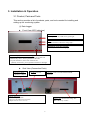
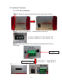
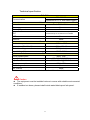
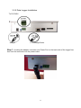
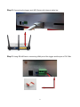
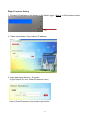
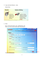
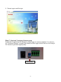
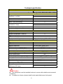
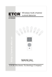
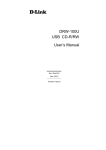
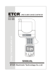
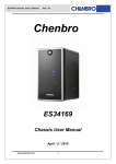
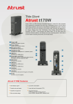
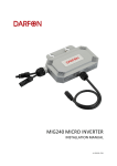
PV Monitoring System PLC Box and Data Logger USER MANUAL 0 Table of Content 1. Safety Information………………………………………………………………..2 1.1 Notifications………………………….……………………………………2 1.2 Symbols…………………………..….……………………………………2 1.3 Intended use and Safety Warnings.……….……………………………2 1.4 Safety of Installation and Operation.……………………………………3 1.4.1 Planning for Installation and Servicing.…………………..……3 2. Introduction…………………………..….…………………………………………4 3. Installation & Operation…………………………………………………………..5 3.1 Product , Parts and Tools………..….…………………………………..5 3.2 Connection………………………..….…………………………………...8 3.2.1. PV module system with the monitoring system layout plan..8 3.2.2. Monitoring system setup plan………………………………....8 3.3 Installation Procedure………………………………………...…….…..10 3.3.1 PLC box Installation…………………………..……….….……10 3.3.2 Data Logger Installation…………………..……..………...…..12 1 1. Safety Information 1.1 Notifications READ THIS FIRST SAVE THESE INSTRUCTIONS: This manual contains important instructions for DARFON monitoring system that shall be followed during installation and maintenance of the micro inverter. Before using this unit, please read these operating instructions carefully. Take special caution to follow the warnings indicated on the unit itself as well as the safety suggestions listed below. 1.2 Symbols To reduce the risk of injury and to ensure sustained safe operation of this product, the following safety instructions and warnings are used in this manual. ! Warning, risk of electric shock The lighting flash with arrowhead symbol, within an equilateral triangle, is intended to alert users of the presence of dangerous voltage within the product’s enclosure that may pose a risk of injury or death for users and/or installers. Caution (refer to accompanying documents) The exclamation point within an equilateral triangle is intended to alert the users of important information to prevent damage to this product. 1.3 Intended use and Safety Warnings Warning Risk of Electric Shock. Do Not Remove Cover. No User-Serviceable Parts Inside. Refer To Qualified Personnel for Servicing. Repairs and internal servicing should only performed by authorized service personnel. 2 ! Caution Perform all electrical installations in accordance with all applicable local electrical codes and the National Electrical Code (NEC), ANSI/NFPA 70. 1.4 Safety of Installation and Operation 1.4.1 Planning for Installation and Servicing For safety of installation, personnel must remove all conductive jewellery or equipment during the installation or servicing of the parts, connector, and/or wiring. The permanently wired equipment must be installed by licensed electricians. Please follow all the instructions carefully and adhere to all the information on cautions or warnings. Installation of the device must be in accordance with the safety regulations and all other relevant national or local regulations. Read all instructions and cautionary marks in the manual carefully before starting the installation. Switch off circuit breakers before installation and wirings. Do not stand on a wet location while doing installation and wirings. Enclose the outer covering well before switching on the circuit breakers. Only qualified electricians should carry out alterations allowed on your electrical system. Only the trained qualified personnel are required to mount, operate, correct or repair this device. This list does not contain all measure pertinent to the safe operation of the device. If any special problems arise which are not recorded in this manual, please contact our authorized dealer, service partner, or DARFON customer care for information. 3 2. Introduction Thank you for choosing the DARFON as your monitoring system. This document contains important information for installing and setting up this product. It is highly recommended that you read this manual carefully before starting the installation and setup of this product. This monitoring system is a compact unit installed along with PV modules/micro inverters to monitor AC power generated by solar module system. There are two components that make up this monitoring system, which are: DARFON monitoring system – PLC box and data logger (both to be bought separately) 4 3. Installation & Operation 3.1 Product, Parts and Tools This section provides a list of products, parts, and tools needed for installing and setting up the monitoring system. (1) Data Logger Front View (LED Indicators) Power On/Off While power on ok, LED shows green light. LINK With RS-485linked, LED shows orange light。 Equipment connection checking Power on, LED flashes orange light Data Back-up (One-button Back-up) 1. Press and hold the button for 5 seconds, the system will automatically start to back up the data to SD card. 2. If press the button, the screen will show the Quantity of inverters, power generation and error messages. Side View (Connection Ports) Termination Resistor Function as below (Section 3-3, Step 6) Link Port RS-485 to PLC box LAN Port Cat.5E or 6 Cable Line with Standard 568A/B connector Adapter Power Port Standard adapter attached (Input: AC 100-240V 0.48A 47-63Hz) (Output: DC+9V 2A or 12V 1A) SD Card Slot Need to insert SD card while using “OneButton Back-Up” solution 5 Rear View RESET Button While the logger is power-on, pressing this button for 5 seconds and release, the logger will re-start with default settings. (2) Parts AC Adapter RS485 Connector and Wall-mounted Frame Ethernet Cable 6 (2) PLC box Power (Green Procedure Signal (4 Green LED) Link (Orange LED) LED Lighting 1.Start When AC power is connected (see Section 3-3), power and signal LED will blink 3 times. After that signal LED went out, only power LED will lighting. 2.Link When RS-485 is connected, Link (Orange LED) will keep blinking, that means Data Logger and micro inverter communication works normally. 3.Signal Reset 4 Green LEDs show PLC signal intensity (1=> 4 ,Weak => Good) Weak : Good: When “Reset” button is pressed, it will proceed above procedure 1~3. (3) Tools • Torque wrench, sockets, wrenches for mounting hardware • Adjustable wrench or open-ended wrench (for terminators) 7 3.2 Connection 3.2.1. PV module system with the monitoring system layout plan Your plan for the layout of the PV panels will affect the wiring and cabling schemes accordingly, as distance between each panel module will be limited by the cable length. 3.2.2. Monitoring system setup plan Case1 (cat5e connection) If data logger is nearby router/AP, it can be simply use cat5e wire with RJ45 connector to connect data logger and router/AP. The PLC BOX need to be installed before the breaker INDOOR 8 OUTDOOR Case2 (Power Bridge Connection) Power Bridge is suggested to be use if the datalogger needs to be located away from the router. The Power Bridge can replaces obsolete RS-485 cabling and unreliable wireless connectivity in today's solar installations. And provides a simple, secure connection. Less wiring effort and labor cost will be save in this case. Please install Power Bridge with following step. Plug the other Power Bridge into an AC outlet near the data logger and attach the Ethernet cable to the Power Bridge. Plug one of the Power Bridge into AC socket near by the router and attach an Ethernet cable to the Power Bridge. Following Power Bridge model is recommand: Vendor : Asoka SolarLink 9650-WT Ethernet Adapter www.asokatech.com Vendor : TP-link AV200 Nano Powerline Adapter TL-PA2010 http://www.dlinktw.com.tw 9 3.3 Installation Procedure 3.3.1 PLC box Installation Step 1. Remove 2 screws on left side red cover (use wrench 2.5mm) Step 2. Connect AC power to L、N terminal with screw driver L connect to DARFON AC Cable “BLACK” Line N connect to DARFON AC Cable “WHITE” Line Step 3. Connecting RS 485 communication port wiring from PLC box to Data logger. TR Switch Connect to Logger 10 PLC RS- 485 T+ → Logger RS-485 T+ PLC RS- 485 T- → Logger RS-485 T- Technical specification PLC BOX Communication Internal Memory Memory Expansion PLC RS-485/422 (Connector to PC or Web Data Logger) Visualization Flash ROM 16K bits None None Transmission distance: Max. 30m (100ft) * Recommend up to 30 sets micro inverters USB Ethernet None None General data Ambient temperature dimensions (D x W x H) in mm Protection rating Input Voltage(V) -10°C to +50°C 174 x 115 x 49 IP20 (Indoor) AC100~240V Power Power consumption MAX. 10W Input Voltage 100~240VAC 50-60Hz Input Current MAX. 100mA@100VAC Power consumption MAX. 10W Out Voltage None Our Current None * distance from the inverter at the farthest end of a AC branch to PLC ! Caution The equipment must be installed indoors in rooms with suitable environmental conditions . If installed out-doors, please install inside water/debris proof sub-panel. 11 3.3.2 Data Logger Installation To PLC BOX Adapter To Gateway/Router Step 1. Hooking the adapter connector into Power Port on the back side of the logger first, then look the connector into the power outlet. 12 Step 2. Connecting the logger and (AP) Router with internet cable line. Step 3. Using RS-485 line to connecting LINK port of the logger and the port of PLC Box 13 Step 4. After above connections, the display of the logger will show below information. (Suggest to record IP address for below Internet setting) If pressing the button at the right corner, the display of the logger will show the information including “Today Energy”, “Total Energy”, “Number of Device” connected, and “Error Message”. 14 Step 5. Internet Setting 1. Checking IP address on the display of the Data Logger. (Step 4, or Press below button) 2. Open web browser, Key in above IP address 3. Login and select Monitor – Overview (Login Default ID: user, Default Password: user) Key in ID and Password, then press Login button 15 4. Login and select Monitor – Overview Select Overview 5. Overview 16 Step 6. Others (Changing password) 1. Open web browser, Key in above IP address 2. Login and select Monitor – Overview (Login Default ID: user, Default Password: user) Key in ID and Password, then press Login button 17 3. Login and select Monitor – other Select Other 4. Other Key in old account name: user, old password: user Key in your new account name and new password Then press save button 18 5. Please Logout and Re-Login Step 7. (Optional) Terminator Resistor setup Sometimes, if signal from PLC Boxes to a Data logger is severely impacted. You can turn on “Terminator Resistor” (turned off by default) on the Logger and the last one of a string of PLC boxes to get better signal quality. ON: Push up 19 Technical specification Data Logger 1 x RS458/R5422 to connect with 1 PLC (max. distance 500 meters or 1600 ft) Communication Plant monitoring String monitoring v (depends on model) v Inverter failures v Performance monitoring for each inverter v Status / fault monitoring v Connection to sensor system v (irradiation / temp) v Email alarm+ v Local alarm(Light / sound) v Visualization Integrated web server v Graphic visualization - local PC v Graphic visualization - internet v LED status display v Display on device (option) 3.5" graphic display (192 x 128dots) Interfaces Ethernet network v USB stick v Memory expansion SD Card (Max. SDHC 32G) Wi-Fi Optional. Int. USB Wi-Fi dongle Modem analogue / GPRS(GSM) Optional. Int. RS-232 interface General data Mains voltage / device voltage 220V / 12V Power consumption 4W Ambient temperature -10°C to +50°C Housing / dimensions (W x H x D) metal / 200mm x140mm x 45mm Installation Wall mount Protection rating IP 20 (for indoor use only) Memory, micro SD, 4 GB v Backup to external memory v (USB stick, SD Card) v ! Caution The equipment must be installed indoors in rooms with suitable environmental conditions . If installed out-doors, please install inside water/debris proof sub-panel. 20 Manufactured by: DARFON ELECTRONICS CORP. 167 Shan-ying Road, Gueishan, Taoyuan 333, Taiwan, (R.O.C.) Tel: +886 3 2508800 www.DARFON.com US Office: Darfon America Corp. 3031 Tisch Way, STE 610 San Jose, CA 95128 Tel: +1 408 260 3880 21