1
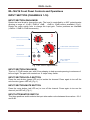
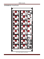
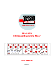
REAL Innovation ML-166/16 16 Channel Summing Mixer 0 R L 0 9 0 PAN -1 +3 SOLO LEVEL -6 -12 0 1 R 0 L +1 SOLO R MUTE +2 MUTE L +1 R 0 MUTE L R 0 INS 2 INS 3 INS 4 MUTE SOLO +3 -2 -1 0 MASTER +2 AUDIO INS-5 RETURN L R INS 5 INS OFF +1 -1 SOLO SUB PHASE SUMM LEFT 1-2 RIGHT 5-6 R MUTE Issue 0.1 0 +1 +2 -2 +3 -1 SOLO +3 -2 MUTE +2 LEVEL -12 9 6 4 8 10 -6 0 0 MONITOR 6 2 8 0 DAC LEVEL OFF 1 MONO 4 6 0 10 2 CD 10 SOLO MONITOR MONSTER MASTER User Manual R -6 1 L L +1 -12 7 0 8 0 LEVEL 2 +3 INPUT 5 0 PAN 0 3 +2 -2 0 -6 -12 4 +3 -2 R LEVEL 0 +2 -6 -1 SOLO +3 -6 -12 +3 LEVEL 7 +2 LEVEL 0 +1 L +1 -2 -2 -12 PAN MUTE MUTE 0 0 -1 MUTE SEND L R 0 SOLO -6 PAN +2 -6 -12 0 R +1 -1 LEVEL -12 0 6 L +1 LEVEL 0 INSERT INS 1 0 +3 -2 MUTE -6 -1 SOLO +3 -2 -6 -12 R +2 LEVEL -6 0 L +1 0 PAN +2 LEVEL 0 16 R L +1 -1 SOLO -12 0 PAN MUTE +3 -2 MUTE 5 0 0 PAN -6 -1 SOLO +3 SOLO R L +1 0 15 +2 LEVEL -12 0 PAN +2 -2 +3 -2 MUTE 4 0 0 -1 +2 -6 +1 LEVEL -12 -1 SOLO R L +1 LEVEL -12 3 -1 SOLO +3 -2 +3 -2 MUTE 0 PAN -6 0 SOLO 0 0 14 PAN +2 -6 +2 LEVEL -12 -1 LEVEL -12 0 -1 SOLO +3 -2 +3 R L +1 -3 PAN -1 0 0 13 PAN +2 -2 MUTE 0 0 R L +1 -1 2 0 PAN SOLO +3 -2 MUTE -6 0 0 0 12 PAN +2 LEVEL -12 R L +1 0 11 PAN +2 -2 MUTE L 0 PAN -1 SOLO R L +1 0 10 8 PHONES 2 SPEAKER PHONES ML - 166 RE EAL Aud dio SAFET TY INSTRUCTIO ONS W WARN NING w the precautio ons listed below w to avoid any possibility of serious injury or even death from electrical shock, short-Always follow circuiting, dam mages, fire or other hazards. These precau utions include, but are not lim mited to, the folllowing: Do not expose e the instrument to liquids an nd rain. Do nott use it near water w or in dam mp or wet conditions, or place e containers on it containing liqu uids. If any liqui d seeps turn offf the power and unplug the pow wer cord from th he AC outlet. Do not put burrning items, such as candles, o n the unit. A burning item may fall over and caause a fire. This instrumen nt contains no user-serviceable u e parts. Do not open the instrument or attemppt to disassemblle or modify the e internal circuit.. Never insert orr remove an ele ectric plug with w wet hands. Check the elecctric plug period dically and remo ove any dirt or dust which may have h accumulatted on it. Do not place the t power cord near heat sourcces such as he eaters or radiato ors, and do not excessively bend or otherwise e damage the cord, c place heavy objects on it, or place it in n a position wh here anyone coould walk on, trip over, or rolll anything over it. C CAUTI TION w the precautio ons listed below w to avoid any possibility of serious injury or even death from electrical shock, short-Always follow circuiting, dam mages, fire or other hazards. These precau utions include, but are not lim mited to, the folllowing: Do n not connect the instrument to an a electrical outllet using a multtiple-connector. Doing so can re result in lower sound quality, orr posssibly cause overrheating in the outlet o itself. Whe en removing the e electric plug from the instrume ent or an outlet, hold the plug itself and not thee cord. Pulling by the cord can n dam mage it. Rem move the electriic plug from the outlet when the instrument is not to be used u for extendded periods of time, or during g electtrical storms. Do n not place the insstrument in an unstable u position n where it mightt accidentally fa all over. Befo ore moving the instrument, remove all connectted cables. Whe en setting up the e product, make e sure that the AC outlet you are a using is eas sily accessible. If some trouble e or malfunction n occu urs, immediatelyy turn off the po ower switch and d disconnect the e plug from the outlet. Even whhen the power switch s is turned d off, e electricity is still flowing to the product p at the m minimum level. Whe en you are not using u the produc ct for a long time e, make sure to o unplug the pow wer cord from thhe wall AC outle et. Use only the stand//rack specified for f the instrume ent. When attaching the stand or o rack, use thee provided screw ws only. Failure e o so could causse damage to the internal comp ponents or result in the instrume ent falling over. to do In nformatio on for Users on C Collection n and Dis sposal off Old Equ uipment This special syymbol on the products, packag ging, and/or acccompanying do ocuments means that used eleectrical and elec ctronic productss should not be m mixed with gene eral household waste. For proper trea atment, recoverry and recycling g of old productts, please take them t to applica able collection ppoints, in accord dance with yourr national legisla ation and the Directives 2002/96/EC. By disposing o of these productts correctly, you u will help to sa ave valuable res sources and pre event any potenntial negative efffects on human n health and the environment which w could otherwise arise from m inappropriate waste handling. ecycling of old p products, please e contact your lo ocal municipalitty, your waste disposal d service e For more inforrmation about collection and re or the point of sale where you purchased the items. s users in the European E Union] [For business If you wish to d discard electrica al and electronic c equipment, ple ease contact yo our dealer or sup pplier for furtherr information. [Information o on Disposal in other Countrie es outside the European Unio on] This symbol iss only valid in th he European Un nion. If you wish h to discard the ese items, pleas se contact your local authorities or dealer and d ask for the corrrect method of disposal. d ML-166/16 User Ma anual, Issue e 0.1 Page 2 RE EAL Aud dio REAL A Audio Contacts C s RE EAL Audio o Via A. Mo ondadori, 7 00128 Ro ome – Italyy T Tel +39 06 6 506 2017 7 F Fax: +39 06 6 5062017 7 Inffo: info@re eal-audio.itt Weeb: www.re eal-audio.itt Support: http://www. h w.real-audio o.it/supportt orking to the improvement of its ssystems and related documentation. REAL Audio iss continuously wo In any case, we e reserve the righ ht to change the specifications s wi thout notice but in the respect to the current legisslation. Disclaimer: The information n contained in this manual has be een carefully cheecked and we bellieved is accurate e at the time of ppublication. In any case, we e do not assume e any responsibiility for inaccuraccies, errors or om missions nor any y liability for anyy loss or damage e resulting eitherr directly or indire ectly from use of the information contained c in this manual. ML-166/16 User Ma anual, Issue e 0.1 Page 3 REAL Audio TABLE OF CONTENTS SAFETY INSTRUCTIONS ................................................................................................... 2 REAL Audio Contacts ..........................................................................................................3 TABLE OF CONTENTS ....................................................................................................... 4 INTRODUCTION .................................................................................................................5 Housing................................................................................................................................ 7 ML-166/16 Front Panel Controls and Operations ................................................................ 8 INPUT SECTION .................................................................................................................8 Input section gain knob .................................................................................................... 8 Input section pan knob ..................................................................................................... 8 Input section solo button .................................................................................................. 8 Input section mute button ................................................................................................. 8 Input attenuator switch ..................................................................................................... 8 Insert section ....................................................................................................................... 9 Monitor section .................................................................................................................... 9 SOLO KNOB ....................................................................................................................9 SOLO LED ....................................................................................................................... 9 MONITOR KNOB ............................................................................................................. 9 MUTE L/R BUTTONS ...................................................................................................... 9 MONO BUTTON ............................................................................................................ 10 Speaker switch ............................................................................................................... 10 Dac button ...................................................................................................................... 10 Cd button........................................................................................................................ 10 Level knob ...................................................................................................................... 10 Phones knob .................................................................................................................. 10 Headphones TRS jack ................................................................................................... 10 Master section ................................................................................................................... 11 Sub button ...................................................................................................................... 11 Phase button .................................................................................................................. 11 Left and rigth master volume knobs ............................................................................... 11 Master section in/out selector ......................................................................................... 11 ML-166/16 Back Panel Controls and Operations ............................................................... 11 INPUT XLR .................................................................................................................... 11 INPUT DB 25 (1 and 2) .................................................................................................. 11 MAIN L/R OUT ............................................................................................................... 11 MONITOR OUT .............................................................................................................. 12 SEND/RETURN 1 and 2 ................................................................................................ 12 OUTPUT DB 25............................................................................................................. 12 APPENDIX A: Connections................................................................................................ 13 APPENDIX B: Front Panel ................................................................................................. 14 APPENDIX C: Back Panel ................................................................................................. 15 TECHNICAL SPECIFICATIONS ........................................................................................ 17 ML-166/16 User Manual, Issue 0.1 Page 4 REAL Audio INTRODUCTION REAL Audio Monster Master ML-166/16 is the answer to all stream mixing and mastering needs. Its features set it apart from other similar products on the market: each of the 8 mixing channels has an 11-step rotary switch for panning, a 12-step rotary switch for level (going from +3dB to -2.5dB in 0.5dB increments), an input attenuation selection button (0dB, -6dB or -12dB) and mute and solo buttons. The solo function is particularly useful as it works even if the channel is muted: signal is fed to the bus after the pan rotary switch to allow a correct and precise stereo positioning of each signal for each channel. The master section has two master level rotary switches that allow a 3dB-increase or decrease of the output level in steps of 0.5dBs. The internal summing section is totally symmetric (balanced) and built with highest quality components to guarantee maximum signal transparency and quality. The resulting noise is 10 to 12dB lower than other summing mixers. A specific additional feature of the Monster Master is the “Summing Bypass” function, which is extremely useful for mastering an already mixed stereo track. This option allows selective feeding of channels 1 and 2 or 5 and 6 and not the entire summing output to the mastering section. This further reduces noise coming from unused tracks. When channels 1 and 2 or 5 and 6 are directly fed to the mastering section, the level and pan controls for these channels are bypassed and a unitary gain is used. Changing the internal jumper setup can easily restore the effect of the level control rotary switch. The Monster Master is the “All-in-one” solution for the mixing and mastering engineer who do not accept compromises in sound quality and that want maximum flexibility and reliability. An exceptionally robust frame houses only the best available non-custom and non-SMD components. Each channel can be accessed by two different input connectors (DB25 and XLR) allowing hassle-free connections to professional DAW via a standard 8 channel multicore cable (DB25 to DB25) as well as single-channel external device insertion via an XLR cable. Following the summing stage is an insert point for connecting external units such as equalizers and compressors that can be bypassed with a front panel button. This insert connection, electronically balanced for both send and return, can be accessed either from the DB25 and XLR rear connectors or via front panel jacks. This feature is particularly useful when a main external unit (connected via the rear panel) needs to be momentarily replaced by another device quickly. The use of the send/return front panel jacks automatically disables the corresponding rear panel connected device. The send signal on the front panel jacks is always present allowing the set-up of the levels for the outboard connected by the front panel jacks. The connection of the return cable will exclude the main outboard connected to the DB25 connector on the back panel. Therefore a unit can be connected to the front panel jacks maintaining the main insert on the back panel. Used in conjunction with mic preamplifiers, the ML-166/16 is the ideal mixer for engineers working in studios not equipped with a classic analog console who do not want to use digital mixers. For this reason, a different ML-166/16 version characterized by a level control range of -20dB/+6dB is also available. ML-166/16 User Manual, Issue 0.1 Page 5 REAL Audio ML-166/16 is dedicated (due to his absolute sonic level quality) to high professional vocal recordings, classical instruments, high dynamic range instruments such as drums and percussions. REAL Audio products are designed and manufactured in Italy. ML-166/16 User Manual, Issue 0.1 Page 6 REAL Audio Housing The ML-166/16 is contained in a 5U rack metal box. No specific air conditioning is required for the racks, provided that there is a free flow of air through the rack from front to back and the temperature is maintained in the operating range. Consequently the racks may be stacked. ML-166/16 User Manual, Issue 0.1 Page 7 REAL Audio ML-166/16 Front Panel Controls and Operations INPUT SECTION (CHANNELS 1-16) INPUT SECTION GAIN KNOB Rotate the level knob to change the gain. The level is controlled by a 300° potentiometer allowing a range of 14 dB (-12dB to +2dB, +6dB to -20dB version available) (Fig.1). Rotate the rotary switch from to change the input gain. Twelve positions are available (+3dB to -2.5dB in 0.5dB increments). 3 0 11 STEPS ROTARY SWITCH PAN-POT R L 0 +1 PAN MUTE BUTTON 12-STEP ROTARY SWITCH INPUT GAIN -1 SOLO MUTE SOLO BUTTON +2 -2 +3 LEVEL -6 -12 INPUT ATTENUATOR 0 / -6dB / -12 dB 0 Fig. 1 ML-166/16 Input Section INPUT SECTION PAN KNOB This is a -3.75 dB centre pan, with S-Law shaping to help accurate panning to extremes of left and right. The pan knob controls an 11 steps rotary switch. INPUT SECTION SOLO BUTTON Press the solo button (green LED on) to isolate the channel. Press again to turn-off the solo function (green LED off) (Fig. 1). INPUT SECTION MUTE BUTTON Press the mute button (red LED on) to turn off the channel. Press again to turn-on the channel (red LED off) (Fig. 1). INPUT ATTENUATOR SWITCH This three positions switch selects the input attenuation value between three values -12/-6 and 0 dB. ML-166/16 User Manual, Issue 0.1 Page 8 REAL Audio Insert section Push the back illuminated buttons to select the main inserts (Fig. 2). Insert 5 can be selected by pressing INS 5. Insert 5 can be connected by using the jacks on the front panel. Press INS OFF button to exclude all the inserts. Press the SOLO button to monitor the pre insert audio signal. INSERT 2, 2, 3, 4 BACKILLUMINATED BUTTONS (RELAY SWITCH) BACK PANEL XLR CONNECTORS INSERT INS - 1 INS - 2 INS - 3 INS - 4 INSERT MONITORING PRE INSERT SOLO BUTTON SEND L R INS-5 RETURN L R INS 5 INS OFF SOLO AUDIO BY-PASS INSERT (ALL INSERTS) INSERT 5 FRONT PANEL JACKS BY-PASS INSERT 5 BUTTON Fig. 2 ML-166/16 Insert Section Monitor section SOLO KNOB Turn the SOLO gain knob (Fig. 3) in order to select the required amount of gain for the SOLO bus. SOLO LED The green LED on means that the SOLO function is activated. MONITOR KNOB Turn the MONITOR gain knob (Fig. 2) in order to select the required amount of gain for the monitor outputs. MUTE L/R BUTTONS Push the MUTE L or MUTE R button to mute the L or the R channel (red LEDs on). Press again to switch off the MUTE L/R function (red LEDs off). ML-166/16 User Manual, Issue 0.1 Page 9 REAL Audio DAC LEVEL CONTROL BUTTON CD/DVD READER LEVEL CONTROL BUTTON CD/DVD-DAC LEVEL KNOB HEADPHONE LEVEL 4 5 3 8 1 R 9 0 6 4 7 2 MUTE L MONITOR 6 4 8 2 0 10 LEVEL OFF 1 MONO 0 10 PHONES 2 SPEAKER MONSTER MASTER 8 2 CD 10 SOLO MONITOR DAC 6 PHONES MS - 166 HEADPHONE OUTPUT JACK Fig. 3 ML-166/16 Monitor Section MONO BUTTON Push the button to obtain a single mono output (red LED on). Press again to switch off the MONO function (red LED off). SPEAKER SWITCH Select one of the three positions of the SPEAKER toggle switch (Speaker 1, OFF, Speaker 2) to select the speaker system. DAC BUTTON Push the button to select the DAC input (red LED on). Press again to disconnect the DAC input (red LED off). CD BUTTON Push the button to select the CD/DVD input (red LED on). Press again to disconnect the CD/DVD input (red LED off). LEVEL KNOB Rotate the knob to change the level of the selected input source. PHONES KNOB Rotate the knob to change the headphone volume. HEADPHONES TRS JACK Connect the headphone to this TRS jack. The headphone amplifier is able to drive headphones with impedance > 50Ω. ML-166/16 User Manual, Issue 0.1 Page 10 REAL Audio Master section 0 +1 0 MASTER +1 12-STEP ROTARY SWITCH MASTER VOLUME FOR L/R CHANNELS -1 +2 +3 -2 SUB PHASE -1 +2 +3 -2 SUMM LEFT 1-2 RIGHT 5-6 INPUT SUBSONIC FILTER 18 Hz 12 dB/oct MASTER SECTION INPUT SELECTOR INPUT 1/2 - SUMM - INPUT 5/6 PHASE REVERSE BUTTON Fig. 3 ML-166/16 Master Section SUB BUTTON Push the button to activate the subsonic filter (red LED on). Press again to deactivate the filter (red LED off). PHASE BUTTON Push the button to activate the PHASE REVERSAL (red LED on). Press again to deactivate the function (red LED off). LEFT AND RIGTH MASTER VOLUME KNOBS Rotate the L and R knobs to adjust the master level. 12 positions are available (Rotary switch) from +3dB to -2.5dB in 0.5dB increments MASTER SECTION IN/OUT SELECTOR Select one of the three positions of the INPUT switch (1/2, SUMM,5/6) to select the input channels. ML-166/16 Back Panel Controls and Operations INPUT XLR The 16 XLR female connectors for the input channels are clustered ion two groups of 8. INPUT DB-25 (1 AND 2) Two DB-25 can also be used for the input channels connections. Each DB25 accommodate 8 input channels (occorre mettere il cabling) MAIN L/R OUT XLRs for the L/R main output. ML-166/16 User Manual, Issue 0.1 Page 11 REAL Audio MONITOR OUT XLRs for the L/R monitor output SEND/RETURN 1 AND 2 XLRs for the send/return 1 and 2. OUTPUT DB-25 The output DB-25 connector is used to simplify the output connections by a using a signle multicore cable. (Fig. XXX) ML-166/16 User Manual, Issue 0.1 Page 12 REAL Audio APPENDIX A: Connections FIG. 1 ML-166/16 Connections ML-166/16 User Manual, Issue 0.1 Page 13 ML-166/16 User Manual, Issue 0.1 SOLO SOLO R R -1 -1 AUDIO INS 1 MUTE PAN L 0 MUTE PAN L 0 -12 -2 0 -12 -2 0 R -1 +3 +1 SEND L R INS 2 INS-5 RETURN L R INS 3 -12 -6 -2 0 LEVEL MUTE PAN 2 -6 0 +2 SOLO L 0 +3 +1 LEVEL +3 +1 1 -12 -2 0 -6 MUTE -1 -6 SOLO PAN R 10 LEVEL 0 +2 L 0 LEVEL +3 +1 9 0 +2 0 +2 INS 5 R R MUTE PAN L 0 MUTE INS OFF INS 4 SOLO SOLO PAN L 0 -1 -1 +3 -6 LEVEL +3 +1 3 -6 LEVEL -3 +1 SOLO INSERT -12 -2 0 -12 -2 0 11 0 +2 0 +2 SUB SOLO SOLO R R PHASE MUTE PAN L 0 MUTE PAN L 0 -1 -1 -1 -2 0 +3 +1 +3 +1 -6 LEVEL +3 +1 4 -6 LEVEL LEFT -12 -2 0 -12 -2 0 12 1-2 +2 0 +2 0 +2 INPUT SUMM R R MUTE PAN L 0 MUTE 5-6 MASTER SOLO SOLO PAN L 0 -1 -1 -1 -2 0 +3 +1 -6 LEVEL +3 +1 5 -6 LEVEL +3 +1 RIGHT -12 -2 0 -12 -2 0 13 +2 0 +2 0 +2 L R R R MUTE PAN L 0 MUTE MUTE SOLO SOLO PAN L 0 2 3 1 -1 -1 5 -6 10 6 9 7 0 8 +2 0 +2 -1 -1 -12 -2 0 -12 -2 0 OFF SPEAKER 1 8 MONITOR 10 6 MUTE R R SOLO 0 4 0 MUTE PAN L MONO 2 SOLO SOLO PAN L 0 MONSTER MASTER LEVEL +3 +1 6 -6 LEVEL +3 +1 MONITOR 0 4 -12 -2 0 -12 -2 0 14 7 2 CD 0 +2 0 +2 ML - 166 DAC -6 LEVEL +3 +1 -6 LEVEL +3 +1 15 R R MUTE PAN L 0 M U TE LEVEL SOLO SOLO PAN L 0 -1 -1 2 8 10 6 -6 PHONES 8 LEVEL +3 +1 -6 LEVEL +3 +1 PHONES 0 4 -12 -2 0 -12 -2 0 16 0 +2 0 +2 REAL Audio APPENDIX B: Front Panel FIG. 3 ML-166/16 Front Panel Page 14 SN v DESIGNED AND MANUFACTURED IN ITALY ML 166 AUDIO RISK OF ELECTRIC SHOCK DO NOT OPEN CAUTION POWER R L CD/DVD ON FUSE ML-166/16 User Manual, Issue 0.1 OFF WARNING TO RAIN OR MOISTURE SHOCK DO NOT EXPOSE THIS EQUIPMENT TO REDUCE THE RISK OF FIRE OR EJECTRIC VU RIGHT ML - 166 / 16 AUDIO RIGHT R E T R E T S E N D S E N D S E N D M O N 2 D A C 15 INSERT R E T S E N D 3 R E T LEFT 4 M O N 1 M A I N LEFT INPUT 16 2 14 R E T S E N D S E N D R E T R E T S E N D 9 - 16 R E T S E N D 1 13 12 11 8 7 6 5 1-8 INPUT 10 4 3 2 1 9 REAL Audio APPENDIX C: Back Panel Fig. 4 ML-166/16 Back Panel Page 15 REAL Audio APPENDIX C: Input and Output DB-25 connectors ML-166/16 User Manual, Issue 0.1 Page 16 REAL Audio TECHNICAL SPECIFICATIONS Number of Channels Power Supply Operating Voltage Power Consumption 16 Linear Regulator (Balanced C-Core Transformer) 220V 50 Hz/ 110 V 60 Hz switchable 50 W Electronically balanced, Level +4 dBu max +24 dBu Input Impedance > 10 KΩ 12-step level rotary switch from +3dB to -2.5dB in 0.5dB Channel Gain increments with input attenuator selection switch (0dB or 6dB or -12dB) Electronically balanced, Master Output Output Impedance 50 Ω (minimum external load 600Ω) Level +4dBu, Max +29dBu, 12-step level rotary switch from Master Level +3dB to -2.5dB in 0.5dB increments Master Sub filter 20 Hz 12 dB/Oct Slope Stereo, Line level +4dBu max +24dBu, balanced, Imp. DAC Input >10kΩ CD Input Stereo. Level -10dBu, Imp. >10kΩ, unbalanced Bandwidth 5 - 200.000 Hz -1dB, perfect square wave up to 20 KHz Distortion + Noise <0.005% ( typical 0.001 %) 12-step rotary switch from for level control (+3dB to -2.5dB in 0.5dB increments), Front Panel Controls (each 3 positions input attenuation switch (0dB or -6dB or -12dB), channel): Input Section 11-Step pan rotary switch. 2 x buttons for mute and solo Front Panel Controls: Insert 4 x backlighted buttons (INSERT 1 to 4 enable). Section 3 x buttons (Insert 5, Insert OFF, Solo) 2 x 12-step level rotary switch, (+3dB to -2.5dB in 0.5dB Front Panel Controls: steps) for L/R Channels Master Section 2 x buttons (Subsonic Filter, Phase) Toggle switch input mode (1+2, Sum, 5+6) 4 x pots (Monitor, Solo, CD-level, Headphones) Front Panel Controls: 5 x buttons (Mute L, Mute R, Mono, DAC, CD) Monitor Section 3-way toggle switch speaker mode (Speaker 1, OFF, Speaker 2) Input Section (each channel): Insert Section: yellow LED (Solo), red LED (Mute), Master Section:4 x backlighted button (INS 1-4), 2x red LEDs Front Panel Indicators (INS 5, INS off), yellow LED (Solo), Monitor Section: 3x red LED (Mute L, Mute R, Mono), 2X green LED (DAC, CD) 4 x 1/4” TRS jack for INSERT 5 (send L-R, return L-R), Front Panel Connnectors 1 x 1/4” stereo jack for headphones Imp. >50Ω Rear Panel Input 8 x Balanced XLR female (Ch1 to Ch8) ML-166/16 User Manual, Issue 0.1 Page 17 REAL Audio Connectors Rear Panel Output Connectors Rear Panel Insert Connectors Main Switch Rear Panel AC mains Construction Dimensions Weight DB25 female (Ch1 to Ch8), 2 x Balanced XLR female (DAC input), 2x RCA (CD/DVD input) 6 x Balanced XLR male (Main, Mon 1, Mon 2). 1/4” jack stereo VU meter connection 8 x Balanced XLR female: Send 1 to 4 (LEFT), Send 1 to 4 (RIGHT) 8 x Balanced XLR male: Return 1 to 4 (LEFT), Return 1 to 4 (RIGHT) Power On/Off switch IEC C13 16 A connector, AC mains cord with IEC Schuko 16A 19" 5U rack mount metal box W 483 mm / 19”, H 225.25 mm/1.75” (1 RU), D 225 mm / 8.86” 9 kg ML-166/16 User Manual, Issue 0.1 Page 18