1
English
Operating instructions
9
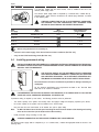
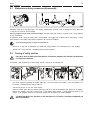
A 4 pole plug, suitable with the current socket, must be installed at the end of the
device's power supply cable.
The device’s power supply cable is composed by 4 coloured wires, marked with appropriate bands, which must be connected to the relevant plug’s terminals, as shown
in the following table.
A WRONG CONNECTION IN THE PLUG’S INSIDE MAY CAUSE SERIOUS DANGER. FOR THE CONNECTION, ONLY ADDRESS YOUR
SELVES TO QUALIFIED AND AUTHORIZED TECHNICIANS.
Kind
of supply
Wire
colour
Wire
marking band
Code marked near
plug’s terminal
GROUND
GREEN/YELLOW
None
Phase R
BLACK
R or L1
Phase S
BROWN
S or L2
Phase T
BLACK
T or L3
PE or
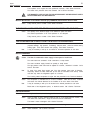
Before using the device it is necessary to:
-
connect it to the water supply, if the device features a water condenser (Ref. Par. 5.4);
-
carry out the initial functioning check (Ref. Par. 5.5).
5.4
Installing permanent wiring
INSTALLATION MUST BE PERFORMED BY A LICENCED ELECTRICIAN / REFRIGERATION TECHNICIAN.
INCORRECT INSTALLATION COULD CAUSE PERSONAL INJURY, SEVERE DAMAGE TO THE MACHINE
AND WILL VOID THE WARRANTY.
THE ELECTRIC SAFETY OF THIS AUTOMATIC DEVICE IS REACHED
ONLY WHEN THE SAME IS CORRECTLY CONNECTED, BY QUALIFIED
AND CERTIFIED PERSONNEL, TO AN EFFICIENT GROUNDING SYSTEM, MADE AS PROVIDED FOR IN FORCE SAFETY REGULATIONS.
The manufacturer will not be considered responsible for damage caused by an
inadequate.
All the electrical specifications and requirements are listed on the Technical Data
Plate and on the Technical Handbook.
FOR PREPARING THE ELECTRIC AL SUPPLY FOR THE DEVICE, IT IS COMPULSORY TO FOLLOW THE
STATE AND LOCAL CODES AND STANDARDS. IN PARTICULAR:
If permanent wiring is required by local codes, the following procedure must be performed:
-
The electric capacity of the system must exactly match the supply’s voltage and frequency required by the device;
-
the current capacity of the system must be suitable for the device’s input;
-
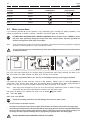
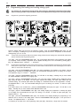
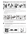
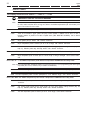
bring the wires from the batch freezer to the breaker box (refer to figure 078b);
Note:
-
for MIX 120-109a remove left side panel and bring the wires from the bottom of the heating and cooling
mixer to the control box (on the bottom side of the machine);
Install permanent wiring according to local code.
A WRONG CONNECTION ON THE GROUND TERMINAL MAY CAUSE SERIOUS.
The device’s power supply cable is composed by 3 or 4 coloured wires, marked with appropriate bands as shown in the
following table.