1
OPERATING INSTRUCTIONS
MIX 60 - 109a
MIX 60 - 309a
MIX 120 - 109a
Z15.032
0907 V01 USA MX
Mixer
US
2
English
Mixer
3
Dear customer,
we congratulate you for choosing a high quality product
which will surely satisfy your expectations.
With our thanks for choosing us,
we kindly invite you to examine the present operating
instructions manual before operating your new device.
SUMMARY
1
2
IMPORTANT SAFETY INSTRUCTIONS AND
PRECAUTIONS .......................................................
4
6. 4
6. 5
Technical data plate and marking................... 5
Acoustic decibal rating ................................... 5
WASHING ............................................................ 16
8
MAINTENANCE................................................... 18
5. 1
5. 2
5. 3
5. 4
5. 5
5. 6
8. 1
8. 2
8. 3
Transportation of the crated equipment ......... 6
Unpacking ...................................................... 6
INSTALLATION ..................................................... 7
Equipment location and parts verification ....... 7
Assembling parts ........................................... 8
Electrical connection ...................................... 8
Installing permanent wiring ............................ 9
Water connections ....................................... 10
Initial functioning check ................................. 11
Warnings ...................................................... 12
Controls and indicators ................................ 12
Programming the heating and cooling mixing
cycle ............................................................. 14
Production .................................................... 15
Partial tap washing ....................................... 16
7
TRASPORTING, LIFTING AND UNPACKING....... 6
4. 1
4. 2
5
6. 1
6. 2
6. 3
Magnetic sensor ............................................. 5
TECHNICAL DATA ................................................ 5
3. 1
3. 2
4
DEVICE’S OPERATION ...................................... 12
SAFETY DEVICES ................................................ 5
2. 1
3
6
9
Maintenance during component disassembly19
Testing of safety devices .............................. 19
Annual maintenance .................................... 20
PERIODS OF INACTIVITY .................................. 20
10 MALFUNCTIONS ................................................ 20
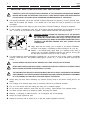
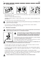
WARNING:
GENERAL/MECHANICAL
DANGER
DANGEROUS
VOLTAGE
DANGEROUS
TEMPERATURE
A TEXT IN UPPER-CASE, IDENTIFIED BY ONE OF THE SYMBOLS ABOVE, CONTAINS INSTRUCTIONS
THAT, IF NOT FOLLOWED, MAY CAUSE HARM TO PEOPLE.
A text in lower-case, identified by this symbol, contains instructions that, if not followed, could cause
damages or malfunctions to the device, or falls in its quality.
English
Mixer
4
1
IMPORTANT
SAFETY INSTRUCTIONS AND PRECAUTIONS
CAREFULLY READ THE INSTRUCTIONS CONTAINED IN THE OPERATING INSTRUCTIONS MANUAL
BEFORE INSTALLING OR OPERATING THIS DEVICE. THESE INSTRUCTIONS HAVE BEEN DRAFTED
FOR THE SAFETY OF INSTALLATION, OPERATION AND MAINTENANCE OF THIS DEVICE.
The Operating Instructions manual and Technical Handbook packed with the equipment, the EC’s conformity certification and the electrical test schedule, is an essential part of the device and must be preserved for any future
consultation.
The technical handbook must always be given to the Service Techician installing or servicing the equipment.
In case of selling or transferring to other user, all the above mentioned documentation must be handed to the new
user, so that he can be informed of the operation, relative technical information and safety instructions.
RESIDUAL HAZARD: DURING THE HEATING CYCLE, THE PRODUCT
BECOMES VERY HOT (+65/149°F...+90°C/194°F). SERIOUS INJURY CAN
BE CAUSED BY CONTACT WITH THE LID [5], THE TAP [11] AND THE
DEVICE'S SURFACE [35]. WHEN LID IS OPENED THE MACHINE STOPS,
HOWEVER, THE MIXTURE REMAINS VERY HOT. PLEASE FOLLOW
THESE RULES:
Always assure that the heating cycle is complete or the product’s temperature,
(as shown on the display), is sufficiently low before opening the lid or the tap.
Attention, if an electrical power supply failure (or a blackout) occurs during a
heating cycle, the mixture’s temperature inside the tub could be still very high
and the device thermometer would not be able to display it.
If in doubt whether the mixture’s temperature is sufficiently low, do not open the lid or the tap, unless it is absolutely
necessary. Should this occur, wear protective clothing (gloves, overalls, etc. ), in order to avoid direct contact with the
product.
DO NOT REMOVE OR HIDE, FOR ANY REASON, ANY LABEL APPLIED ON THE DEVICE.
NEVER OPEN THE SIDE OR BACK PANELS. THE DEVICE DOES NOT CONTAIN, IN ITS INSIDE, PARTS
WHICH CAN BE OPERATED OR SERVICED BY THE USER.
THE USER MUST NOT EXECUTE OPERATIONS WHICH ARE NOT CLEARLY CONTAINED IN THE PRESENT
USER’S MANUAL. ANY OPERATION WHICH REQUIRES TOOLS NOT GIVEN IN THE DEVICE’S EQUIPMENT
IS TO BE CARRIED OUT ONLY BY A QUALIFIED SERVICE THECNICIAN.
Always unplug the device before undertaking any operation requiring access to the device’s moving parts (i. e. the
beater).
Any modifying of the electrical supply must be exclusively performed by professional electrician.
Any use of the machine other than heating and cooling mix is considered improper.
Do not connect and/or operate the device when any part is missing, unleas instruted in the operators manual.
The device has been made to be operated by adults, keep away from children.
Modifying, or attempting to modify this device, can be dangerous and will void warranty.
Always use original replacement parts.
Disposal of this device must be carried out by an epa 608 certified refrigeration technician.
English
Operating instructions
2
SAFETY
5
DEVICES
DO NOT ALTER THE SAFETY DEVICES AND DO NOT OPERATE THE MACHINE IF THE SAFETY DEVICES ARE DAMAGED OR MALFUNCTIONING.
THE MANUFACTURER IS NOT RESPONSIBLE FOR POSSIBLE DAMAGE OR INJURY CAUSED BY ALTERING OR BYPASSING SAFETY DEVICES OR RELATIVE CIRCUITS.
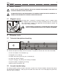
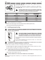
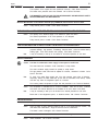
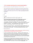
2.1
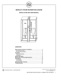
Magnetic sensor
This safety device, composed of an approved magnet [1] and of a magnetic contact
[2] is designed to prevent the stirrer from starting accidentally. There fore, this machine
will not work without a magnet. If the magnet [A] or the rotor lid [B] are removed, the
stirrer stops working immediately.
DURING NORMAL OPERATIONS, THE MACHINE MUST BE STOPPED
ONLY BY THE APPROPRIATE KEYS ON THE CONTROL KEYBOARD.
3
3.1
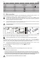
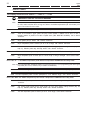
TECHNICAL DATA
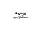
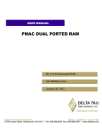
Technical data plate and marking
The technical data plate and marking must not be removed. It is placed on the back side of the device and identifies:
-
the name and address of the manufacturer [1];
-
the designation of the model [2];
-
the relative serial number [3] and the year of construction [4];
-
the voltage and frequency rating [5];
-
the type of cooling [6], the power [7] and current [8] consumption;
-
the type and quantity of refrigerant gas used [9];
-
refrigerant pressure specification [10].
3.2
Acoustic decibal rating
The average equivalent continuous acoustic of this device is quoted in the Technical Handbook (Technical Data section).
This data has been measured at 1 meter (40") from the surface of the device and at 1. 60 meters (630") from ground- level,
during the device’s functioning.
English
Mixer
6
4
TRASPORTING, LIFTING AND UNPACKING
Note:
Should only be carried out by a qualified service technician. Transportation, unpacking and installation.
TO LIFT THE DEVICE ALWAYS USE AN ADEQUATE LIFTING DEVICE.
ATTEMPTING TO LIFT IT MANUALLY IS DANGEROUS AND CAN RESULT IN SERIOUS INJURY.
The device’s weight specifications, both inclusive of packaging and net, can be found
in both the supplied documents and on the packaging itself.
To prevent the oil contained in the compressor from flowing into the refrigeration circuit, the machine
must be kept in an upright position, during carrying and during the installation and operation. Always
follow the instructions on the packaging.
4.1
Transportation of the crated equipment
The packaging has been designed to assure the equipments protection.
It is therefore suggested to transport the device while it is packed as near as possible
to the place where it will be installed.
To carry the packed device, use fork lift, or similar device, inserting its forks into the
holes of the skid.
4.2
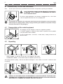
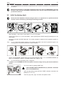
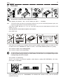
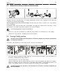
Unpacking
-
WOOD PACKING: pry nails from the top panel, then separate the side panels.
-
CARDBOARD PACKING; cut the bands and pull the cardboard up from the top;
After having opened the packing, make sure the device isn’t damaged. In case of doubt, do not use it. Contact the seller
immediately.
REMOVAL OF SIDE PANELS MUST BE PREFORMED BY A QUALIFIED SERVICE TECHNICIAN ONLY.
EQUIPMENT MUST BE REMOVED FROM CRATING SKID PRIOR TO INSTALLATION AND OPERATION.
MAKE SURE NOT TO DAMAGE THE INTERNAL PARTS OF THE DEVICE.
English
Operating instructions
7
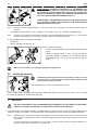
-
Remove both the side panels unscrewing the relevant fixing screws [21];
-
remove shipping bolts at bottom of frame [22];
The power cable is located at the bottom of the machine. Make sure not to damage the cable during the
lifting process.
-
Lift the device from the pallet working from the lower side of the frame near the wheels. Remove the pallet and place
the device on the floor, and lean the device slowly on the floor avoiding bumps;
DO NOT insert objects, ropes or brackets for lifting THROUGH the device, since these could damage the
internal parts.
-
Replace side panels;
-
Packing material, which is produced with entirely recyclable materials (
-
Dispose of packing material properly
5
).
INSTALLATION
THE INSTALLATION MUST BE CARRIED OUT ONLY BY A QUALIFIED SERVICE TECHNICIAN AND IN
COMPLIANCE WITH STATE AND LOCAL CODES. ALWAYS FOLLOW MANUFACTURER'S INSTRUCTIONS.
5.1
Equipment location and parts verification
Place the device on the floor, on a flat and level surface capable of supporting the
equipment's specified weight.
Install the device away from any source of heat, avoiding direct exposure to the sun.
Make sure that air can freely circulate around each side of the device.
Check that all of the listed components are present:
-
lid [5] attached to the machine;
-
Drip tray [26] with bracket [27];
-
Tap [11] including: inner body [12]; piston [13]; cover [14], lever [15]; fastening knob [16];
-
all the technical documentation (in addition to this handbook): the Technical Handbook, the EC’s Conformity Certification and Electrical Test’s Schedule.
English
Mixer
8
5.2
Assembling parts
-
Before inserting the tap, turn the lever [15] fully to the LEFT (OPEN position). Failing to do so might prevent the tap
from fully inserting into the slot;
-
Loosen (do not remove) knurled fastening knob [16];
-
If necessary, lubricate the piston’s O- ring [13], inside the port [3], and their gaskets, with food- safe sanitary lubricant
(NSFapproved);
-
Fully insert tap [11] into the port [3] and tighten fastening knob [16];
Check that the knob’s head [16] is correctly and firmly fixed in the slot [3], to avoid damage to the
gaskets and subsequent leakages.
-
Turn tap’s lever fully to the RIGHT (CLOSED position). Lever should rotate without excessive resistance.
-
Install drip tray [26] (with its bracket [27]) onto the front panel.
5.3
Electrical connection
DANGER HIGH VOLTAGE. HIGH VOLTAGE WILL SHOCK, BURN OR CAUSE DEATH. ANY ELECTRICAL
CONNECTION MUST BE DONE ONLY BY A LICENSED ELECTRICAN.
THE ELECTRIC SAFETY OF THIS AUTOMATIC DEVICE IS REACHED
ONLY WHEN THE SAME IS CORRECTLY CONNECTED, BY QUALIFIED
AND CERTIFIED PERSONNEL, TO AN EFFICIENT GROUNDING SYSTEM, MADE AS PROVIDED FOR IN FORCE SAFETY REGULATIONS.
The manufacturer must not be considered responsible for eventual damages
caused by an inadequate electric or earthing system.
All the electric device's features required for the system’s proportioning are reported
on the Technical Data Plate and on the Technical Handbook.
FOR PREPARING THE ELECTRIC SYSTEM WHICH SUPPLIES THE DEVICE, IT IS COMPULSORY TO
FOLLOW THE PRESCRIPTIVE STANDARDS IN FORCE. IN PARTICULAR:
-
The electric capacity of the system must exactly match the supply’s voltage and frequency required by the device;
-
the current capacity of the system must be suitable for the device’s input;
-
the system must end with an accepted 4 pole electric socket and with electric and mechanical suitable characteristics. The electric socket’s poles must be marked with appropriate letters (phases R- S- T + ground); the earth’s pole
must be recognizable;
-
the electric socket must prevent, through appropriate mechanical measures, the plug’s wrong connection;
-
the electric socket must have, above or annexed, a breaker, conformed to the in force safety laws, with an associated
gearing placed near the device, in a position easily reachable by the operator. It must also be protected by fuses,
above or annexed, with characteristics suited at the current absorbed by the device.
A WRONG CONNECTION ON THE GROUND TERMINAL MAY CAUSE SERIOUS DANGER.
English
Operating instructions
9
A 4 pole plug, suitable with the current socket, must be installed at the end of the
device's power supply cable.
The device’s power supply cable is composed by 4 coloured wires, marked with appropriate bands, which must be connected to the relevant plug’s terminals, as shown
in the following table.
A WRONG CONNECTION IN THE PLUG’S INSIDE MAY CAUSE SERIOUS DANGER. FOR THE CONNECTION, ONLY ADDRESS YOUR
SELVES TO QUALIFIED AND AUTHORIZED TECHNICIANS.
Kind
of supply
Wire
colour
Wire
marking band
Code marked near
plug’s terminal
GROUND
GREEN/YELLOW
None
Phase R
BLACK
R or L1
Phase S
BROWN
S or L2
Phase T
BLACK
T or L3
PE or
Before using the device it is necessary to:
-
connect it to the water supply, if the device features a water condenser (Ref. Par. 5.4);
-
carry out the initial functioning check (Ref. Par. 5.5).
5.4
Installing permanent wiring
INSTALLATION MUST BE PERFORMED BY A LICENCED ELECTRICIAN / REFRIGERATION TECHNICIAN.
INCORRECT INSTALLATION COULD CAUSE PERSONAL INJURY, SEVERE DAMAGE TO THE MACHINE
AND WILL VOID THE WARRANTY.
THE ELECTRIC SAFETY OF THIS AUTOMATIC DEVICE IS REACHED
ONLY WHEN THE SAME IS CORRECTLY CONNECTED, BY QUALIFIED
AND CERTIFIED PERSONNEL, TO AN EFFICIENT GROUNDING SYSTEM, MADE AS PROVIDED FOR IN FORCE SAFETY REGULATIONS.
The manufacturer will not be considered responsible for damage caused by an
inadequate.
All the electrical specifications and requirements are listed on the Technical Data
Plate and on the Technical Handbook.
FOR PREPARING THE ELECTRIC AL SUPPLY FOR THE DEVICE, IT IS COMPULSORY TO FOLLOW THE
STATE AND LOCAL CODES AND STANDARDS. IN PARTICULAR:
If permanent wiring is required by local codes, the following procedure must be performed:
-
The electric capacity of the system must exactly match the supply’s voltage and frequency required by the device;
-
the current capacity of the system must be suitable for the device’s input;
-
bring the wires from the batch freezer to the breaker box (refer to figure 078b);
Note:
-
for MIX 120-109a remove left side panel and bring the wires from the bottom of the heating and cooling
mixer to the control box (on the bottom side of the machine);
Install permanent wiring according to local code.
A WRONG CONNECTION ON THE GROUND TERMINAL MAY CAUSE SERIOUS.
The device’s power supply cable is composed by 3 or 4 coloured wires, marked with appropriate bands as shown in the
following table.
English
Mixer
10
Kind
of supply
Wire
colour
Wire
marking band
GROUND
GREEN
None
Phase R
BLACK
R or L1
Phase S
RED
S or L2
Phase T
WHITE
T or L3
5.5
Code marked near
plug’s terminal
PE or
Water connections
If your machine is provided with an AIR condenser, only a water INLET pipe is necessary (for washing operations). If the
machine is provided with a WATER condenser, both INLET and OUTLET pipes are necessary.
FOR MACHINES PROVIDED WITH A WATER CONDENSER: Do not let water from a TOWER in, unless
they have been specifically designed to utilize water from a tower. Unless otherwise specified, the
machine is designed to utilize water from a WELL.
Note:
In the “Technical Data” section of the Technical Handbook you will find the necessary specifications regarding
the water’s correct temperature in order to operate the machine.
The use if improper hoses or connections may cause water leakage that may result in personal injuries
or damage the device.
Use a 3/4" NPT water supply [D] to the conversion fitting [C] (provided with water cooling machines) 3/4" BSPT to 3/4"
NPT and connect to the water connection 3/4" BSPT [E] on the back of the machine.
Connect only potable water to "E". The use of non potable water may cause hygienic problems.
Use braided steel hoses for water connection, rated for 15 Bar pressures, utilizing a valve or a faucet [B] ABOVE the
delivery pipe; use a 3/4" NPT water supply [D] to the conversion fitting [C] (provided with the water cooling machines) 3/
4" BSPT to 3/4" NPT and connect to the water connection 3/4" BSPT on the back of the machine.
Note:
water supply hoses designed for house use are on the market (ex. dishwashers) which, in addition to being
inexpensive meat the required specifications and utilize a 3/4" NPT water supply.
Pipe unions are placed on the machine's rear panel, they are labelled
IN:
[A] and marked:
fresh water INLET
OUT: waste water OUTLET
Follow the following precautions to avoid damages at the device’s water circuit:
-
do not invert the connection of hoses;
-
if located in a hard water area, install a suitable decalcification or filtration device above the supply pipe;
-
if not otherwise mentioned in the Technical Handbook, water supply pressure must be comprehended between
22 Psi (1.5 Bar) and 87 Psi (6 Bar) (ideal pressure: 44 Psi / 3 Bar). If the pressure of the supply is higher, it is
necessary to install a pressure limiting device, appropriately regulated, above the delivery pipe.
AVOID CONSTRICTION OR NARROW TURNS OF THE HOSES.
English
Operating instructions
Note:
11
The water expelled from the condenser, though being hot and not safe for consumption, is not polluted and can
be reutilised.
Before storing the device in rooms with a temperature lower to 0°C (32°F) it is IMPORTANT to get rid of
the water in the condenser (with WATER condensation) and in the inlet, outlet and washing pipes. Call
your Service technician.
5.6
Initial functioning check
At the end of the installation, and before using the device, it is important to let a qualified technician
check for correct connection, by performing the following procedure.
-
Before proceeding, check that the circuit breaker is in the off ("0") position;
-
insert the plug and turn on ("1") the circuit breaker, only the green light of the START button [Z1] should light up on the
control panel;
-
close the lid and press the START button [K1]. The machine prepares to operate and tank temperature appears on
the display;
Note:
-
press the SLOW BEATING ACTION button [K4] and observe BEATER rotation. If it is COUNTERCLOCKWISE (as
shown in the drawing) the machine is connected correctly and is ready for use;
Note:
-
if “ooo” (three small squares) appears on the display, the impeller cover with it's polarized magnet is not
correctly placed. The machine will not work in these conditions.
do not unnecessarily start heating cycle or refrigerator.
if rotation is in a CLOCKWISE direction, three-phase connection voltage is wrong and must be modified as
follows:
-
Turn off the device by pressing ON/OFF [K1];
TURN THE MAIN CIRCUIT BREAKER OFF ("0") AND PULL THE PLUG
OUT OF THE RECEPTICLE;
-
Open the plug’s shell and invert TWO of the THREE conductors connected at the
phases (R- S, R- T or S- T);
-
Close the plug’s shell, plug in the device and repeat the check.
English
Mixer
12
6
6.1
DEVICE’S
OPERATION
Warnings
WHEN USING THE DEVICE, AS WITH ALL ELECTRICAL APPARATUS, ESSENTIAL RULES MUST BE
COMPLIED WITH, PARTICULARLY:
-
never touch it if your feet or hands are wet;
-
never operate it while barefoot;
-
never unplug the power cord without first turning off the circuit breaker;
-
avoid liquids to penetrate in the device, for example during its cleaning;
-
do not allow children or untrained individuals near this device.
In case of failure and/or malfunctioning of the device - and any time you notice damages, especially at the supply cable or
at the safety devices - turn off the circuit breaker and contact a service technician.
NEVER operate the machine when empty or with an amount of mixture other than the one recommended.
The beater is designed to stir liquids, NOT to grind solids.
NOT RESPECTING THESE RULES, IN ADDITION TO VOIDING ANY FORM OF WARRANTY, CAN SERIOUSLY COMPROMISE THE SAFETY, PERFORMANCES AND FUNCTIONING OF THE DEVICE.
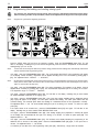
6.2
Controls and indicators
K2
K3
Z1
K1
Z5
Z4
K4
Z7
K7
Z6
K6
K5
K8
Z9 K9
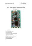
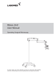
All controls and indicators for the use of the device are grouped in a single control
panel placed on the front panel. It functions on low voltage.
In this manual, the buttons and indicators are identified with the relative symbol, and/
or with an imprint ([K…] for pushbuttons, [Z…] for indicators).
The functioning of every control is described below. To obtain the best results, pease
read carefully before operating the device.
PS10
ON/OFF Pushbutton [K1]
When the electric supply is connected, the machine is ready to be turned on. The green indicator [Z1] will light. When
pressing [K1], the machine is on, a short electronic test is performed and the other pushbuttons are enabled. The display
shows the temperature inside the tank, in °C.
ADJUSTMENT Pushbuttons [K2] - [K3]
These pushbuttons are enabled only after pressing SET UP [K8]. They increase or decrease set values. For more details
on their use, see Par. 6. 3 “Setting Up”.
FAST BEATING button [K4]
On pressing the button, the relative [Z4] light comes on and the beater works CONTINUOUSLY AT HIGH SPEED. This
command can also be inserted during the heating/cooling and preservation cycle. When the button is pressed again, the
beater stops and the light turns off.
English
Operating instructions
13
HEATING/COOLING Pushbutton [K5]
On pressing the button a complete and automatic heating/cooling mixing cycle is set in motion. Once finished, the machine
goes into ageing mode. For further details see Par. 6. 3 - heating/refrigeration cycle.
The [Z5] light remains on until the command has been removed.
SLOW BEATING button [K6]
On pressing the button, the relative light [Z6] comes on and the beater operates CONTINUOUSLY AT LOW SPEED. This
command can also be activated during the heating/cooling and preservation cycle. When the button is pressed again, the
beater stops and the light turns off.
MANUAL REFRIGERATION/PRESERVATION Pushbutton [K7]
When the pushbutton’s indicator [Z7] is on, the machine is in preservation mode: the mixture inside the tub is maintained
at a temperature of approximately 4°C/40°F (or the final preset temperature). The beater, starting at the same time as the
refrigerator, shifts the mixture to keep it homogenous and to maintain a uniform temperature.
To manually activate (light on) or deactivate (light off) the preservation mode, or to interrupt the heating phase during the
heating/cooling cycle and to start the cooling process, simply press this button.
SET UP Pushbutton [K8]
The main heating/cooling and preservation cycle values can be viewed on the display by pressing this button. They can
be adjusted (where necessary) by pressing [K2] and [K3]. For further instructions see Par. 6. 3 and 6. 4 - Programming
WASH Pushbutton [K9]
When pressing, the automatic washing of the tap commences. See also Par. 6. 5 “Washing the tap”.
Digital Display
When turning on and during regular functioning, the display always shows the temperature inside the tank (together with
that of the mixture inside);
-
During set up, the display shows current settings;
-
If “ooo” (three small squares) appear, the impeller cover with it's polarized magnet is not correctly placed, or the
beater motor protection has been activated.
English
Mixer
14
6.3
Programming the heating and cooling mixing cycle
The machine was programmed during testing phase using the standard/recommended values (85°C/
185°F for heating, 4°C/39°F for preservation). These can be adjusted according to one's own requirements.
Note:
-
Press the START button [K1] and once the machine is working, press the PROGRAMMING button [K8]. "P1" will
flash on the display, indicating that you have entered Programming mode and that the temperatures for the automatic
heating/cooling cycle can be set;
Note:
-
Program the cycle before beginning production
If more that 10 second pass without any buttons being pressed the new settings are automatically memorized
and the machine exits Programming mode.
once again, press the PROGRAMMING button [K8]. The recommended (85°C/185°F) high temperature will appear
on the display. Where necessary, temperature can be adjusted according to the mix to be heated by pressing [K2] or
[K3]. The adjustment field is +65/149°F … + 90°C/194°F;
Note:
the idle period preceding the onset of the cooling process, is set automatically according to the chosen temperature (30' for +65°C/149°F, from 65°C/149°F to +85°C/185°F subtract 90'' for each extra degree, from +85°C/
185°F to +90°C/194°F the time is 0).
-
once again, press the PROGRAMMING button [K8]. The ageing temperature (Tcp) appears on the display. It can be
adjusted where necessary by pressing [K2] or [K3]. The recommended temperature (set in the factory) is +4°C/39°F.
The adjustment range is +1°C/34°F. . . +50°C/122°F;
-
once again, press the PROGRAMMING button [K8]. "P2" will flash on the display, indicating that you have entered
the SLOW BEATING FUNCTION of the ageing cycle.
-
once again, press the PROGRAMMING button [K8]. One of the three options available with the adjustment buttons
[K2] or [K3] will appear on the display. The OFF option excludes slow beating; the CONT option allows slow and
continuos beating; the numerical option allows slow beating for a determined amount of time (expressed in minutes).
The adjustment field is 1. . . 60'. The recommended beating time (set in the factory) is 2 minutes. To confirm an option
press [K8].
-
if the option chosen is the numerical one, press the PROGRAMMING button [K8] once again. "P3" will flash on the
display, indicating that you have entered SLOW BEATING IDLE mode.
-
once again, press the PROGRAMMING button [K8]. Slow beating stopping time (expressed in minutes) will appear
on the display. The recommended idle time (set in the factory) is 15 minutes. To confirm an option press [K8]. The
adjustment field is 1. . . 60'.
-
once again, press the PROGRAMMING button [K8]. "P4" will flash on the display, indicating the programming of the
additional time to the term of the heating phase. Press the PROGRAMMING button [K8] again, to set up the time in
minutes. The adjustment field is 1. . . 60 minutes.
-
to memorise pre- set data and to exit Programming mode press [K8]. Alternatively, simply wait a few seconds.
English
Operating instructions
6.4
15
Production
Check that the condenser's water supply faucet is open;
-
Before beginning the production, wash, rinse and sanitize (see section 7 - WASHING).
Note:
If you plan to have more than one consecutive production cycle, you can avoid washing between cycles, making sure you begin with the more neutral flavored mixtures.
-
check that the START light [Z1] is on. If it is not, check that the plug has been inserted properly and that the circuit
breaker is on ("1");
-
check that the lid is closed and the impeller cover in place;
-
press ON/OFF [K1].
-
check that the mix extraction tap is completely turned off (turned completely towards the right) and transfer the mix to
be heated into the tank. MAXIMUM tank capacity is 60 litres, recommended MINIMUM quantities are generally:
-
1/2 of maximum capacity during heating/cooling;
-
1/3 of maximum capacity during preservation.
Too little mixture can cause excessive overheating or the development of ice causing damage or irregular flow and foam during production; too much mixture can slow down or not complete the process of
heating/cooling and cause overspills.
-
add ingredients to heated/cooling;
-
close lid; if you require to pre- blend the ingredients, operate whipper by pressing FAST BEATING[K4], when ready,
press it again, to stop whipper;
-
having programmed (see par 6. 3. PROGRAMMING THE HEATING AND COOLING CYCLE), press the HEATING/
COOLING button [K5];
English
Mixer
16
BURN HAZARD: DURING THE HEATING CYCLE, THE PRODUCT BECOMES VERY HOT (+65/149°F...+90°C/194°F). SERIOUS INSURY CAN
BE CAUSED BY CONTACT WITH THE LID [5], THE TAP [11] AND THE
DEVICE'S SURFACE [35]. WHEN LID IS OPENED THE MACHINE DO
NOT STOP AND THE MIXTURE REMAINS VERY HOT.
ALWAYS VERIFY THAT HEATING/COOLING CYCLE IS COMPLETED OR,
THAT DISPLAY SHOWS A SUFFICIENTLY LOW TEMPERATURE
BEFORE OPENING LID OR TAP.
Note:
-
the total cycle lasts approximately 90…120 minutes and varies according to the mixture quantity, type and
viscosity.
wait until the process is finished. This is signalled on the display by the low conservation temperature [Tcp].
Note:
once the lid is properly closed and the light [Z5] of the [K5] HEATING/COOLING button is on, the machine
monitors and maintains the conservation of the mix at the pre-set temperature [Tcp].
In case ingredients need to be added to the mixture:
-
open the lid;
-
add the ingredients and close the lid;
The mix is extracted as follows:
:
-
turn drip tray [26] sideways and place suitable container beneath
the tap;
-
-
extract the required quantity of mix by turning the extraction
tap counter clockwise. Quantities can be measured using the
gauge supplied [40]. Turn off the tap and place the drip tray
under it;
When all of the mixture is completely extracted, turn machine off.
6.5
Partial tap washing
Immediately following an extraction of mix (however small), all traces
of the mix must be removed from the inside of the tap. This is to keep
the tap clear for a later extraction.
Note: partial washing is carried out with the tap turned off.
Place a container under the extraction tap and press the WASH button [K9]. Allow the water to run until it is clear. Then stop
the process by pressing the WASH button [K9] again.
7
WASHING
THE FATS CONTAINED IN THE ICE CREAM MIXTURES PROMOTE FOR THE GROWTH OF BACTERIA,
CAREFULLY CLEAN AND SANITIZE ALL SURFACES IN CONTACT WITH PRODUCT.
In accordance with current health regulations, complete washing of all parts coming into contact with the product must be
carried out. During such operation, all removable parts must be detached from the machine and washed separately.
Note:
additionally to the operations mentioned in this Chapter, it is recommended to clean machine’s outer panels and
all outside parts, taking particular care to clean drip tray [26] and its bracket [27], after removing them from the
front panel.
To avoid damage to the equipment do not use water in excess of 100°F, solvents, abrasive detergents, or
abrasive cleaning pads, especially on the plastic parts.
English
Operating instructions
17
CARRY OUT THE CLEANING OF THE DEVICE FOLLOWING THESE PROCEDURES:
1 Simple washing
-
Ensure the tap is closed.
-
For models Mix60- 109a and Mix 60 - 309a pour a solution consisting of 4 oz of detergent suitable for use with food
preparation equipment in 8 gallons of hot water (104°F/40°C) into the tank.
-
For model Mix 120- 109a pour a solution consisting of 8 oz of detergent suitable for use with food preparation equipment
in 4 gallons of hot water (104°F/40°C) into the tank.
-
Clean all the tank surfaces and lid, using sterile, disposable material or a suitable brush. Before emptying the tank,
press the stir button [K6] and allow the machine to run for 3 minutes.
-
Rotate the drip tray to one side, position a container under the tap and open it to empty the tank.
-
Rinse the tank with water at room temperature.
-
With the tap still open, press the tap wash button until the water comes out clear.
2 Complete washing and disassembling of the parts
CARRY OUT THESE OPERATIONS ONLY WITH THE MAIN CIRCUIT BREAKER TURNED OFF (“0”).
-
Remove the rod [25] from the lid’s hinge and remove the lid [5].
-
Remove the impeller cover [9] and the impeller [7].
-
Loosen the knurled knob [16] and remove the tap from the port [3]. Unscrew the andle [15], remove the tap cover [14]
and remove the piston [13] from the tap body [12] and the seals [G] (see section 8. 1).
English
Mixer
18
-
Each component mentioned in “Complete washing and disassembling of the parts” must be washed using a suitable
brush in a solution consisting of 2 oz of detergent suitable for use with food preparation equipment in 2 gallons of hot
water (104°F).
-
Rinse each part using water at room temperature.
3 Sanitizing
-
Prepare a solution consisting of 2 oz of Spartan Chemical SANI- T- 10 disinfectant in 2 gallons of water at room
temperature. Immerse all the components mentioned in “accurate washing and disassembling of the parts” in this
solution for 5 minutes.
-
Remove the components from the solution; lubricate the seals and the inner surfaces of the tap joint using lubricant
suitable for use with food preparation equipment. Re- assemble all the sanitized parts.
-
For Mix60 pour a solution consisting of 4 oz of Spartan Chemical SANI- T- 10 disinfectant in 4 gallons of water at room
temperature into the tank. Clean all the tank surfaces and the lid, using disposable sterile material or suitable brush.
Press the stir button and allow the machine to run for 5 minutes before emptying the tank.
-
For Mix120 pour a solution consisting of 8 oz of Spartan Chemical SANI- T- 10 disinfectant in 8 gallons of water at
room temperature into the tank. Clean all the tank surfaces and the lid, using disposable sterile material or suitable
brush. Press the stir button [K6] and allow the machine to run for 5 minutes before emptying the tank.
-
Rotate the drip tray collector to one side, position a container under the tap and open it to empty the tank.
-
The machine should be rinsed first with a sanitizing solution and then with potable water, ensuring that the correct
hygiene procedures are observed, in accordance with state and local health codes.
-
Each time the machine is cleaned, it must be sanitized, using sterile gloves.
regular basis in accordance with local hygiene regulations.
8
Sanitization must be carried out on a
MAINTENANCE
The device requires very limited maintenance. Periodically, we suggest to:
-
check the condition of the parts of the device. During disassembly is an ideal opportunity to inspect parts (ref. Par.
8. 1);
-
check that electric power cable, pipe fittings (rubber hoses) and water pipes are not damaged;
-
Test all safety devices (ref. Par. 8.2).
Examine and clean external panels and surrounding area. Dust, paper fragments or other small objects may block the
ventilation ducts (specially if equipped with air condenser).
Internal parts must only be inspected by a qualified Service Technician (ref. Par. 8. 3)
English
Operating instructions
8.1
19
Maintenance during component disassembly
Periodically check the o- rings [G] shown in the drawing. Replace them if broken, worn or streched out (in the latter case
o- rings tend to come out of their sockets).
Use only original o-rings made of food-safe rubber. The spare parts bag contains a complete set of o- rings approved
by the manufacturer.
A replacement of all o- rings once every year is recommended. We suggest you to always keep a spare supply: to order
them reference to the Spare Parts Section contained in the Technical Handbook.
To correctly replace the o-rings it is necessary to:
-
remove old o- rings with an appropriate non- metalic tool, paying attention not to damage them or their seatings;
-
lubricate new o- rings with food- compatible lubricant before replacing.
8.2
Testing of safety devices
ONLY BY A SKILLED AND QUALIFIED SERVICE TECHNICIAN CAPABLE OF TESTING OR SERVICING
OF THE SAFETY DEVICES
Periodically, check the efficiency of all the safety devices, carrying out the following test:
-
turn off the machine by pressing the START button [K1]. Turn off the Main circuit breaker. If the circuit breaker is off,
the START command light [Z1] will turn itself off;
-
close the lid and turn on the main circuit breaker;
-
press the START button [K1] (the button's green light must be on and the temperature must appear on the display).
Remove the impeller's cover [9] by turning it left. If the magnet works correctly, 3 small squares will appear on the
display, if the magnetic contact is not functioning properly the temperature will remain displayed.
THE MACHINE MUST NOT BE USED IF ONE OR MORE OF THE SAFETY DEVICES IS DAMAGED OR
MALFUNCTIONING!
English
Mixer
20
8.3
Annual maintenance
Periodically (based on the environmental conditions in which the device operates) or at least once every year, make sure
to have a general checkup.
THE CHECK-UP MUST BE MADE BY A QUALIFIED SERVICE TECHNICIAN WITH ADEQUATE TOOLS.
THE MAINTENANCE OPERATIONS CAN BE DANGEROUS IF CARRIED OUT BY NON-PROFESSIONALS,
THEREFORE, FOR YOUR OWN SAFETY, THE USER MUST NEVER CARRY THEM OUT.
9
PERIODS OF
INACTIVITY
If long periods of inactivity are foreseen, proceed as follows:
-
ensure that the Main circuit breaker is turned off;
-
remove the electrical plug from the outlet.
-
Completely clean the device (see Chapter 7);
-
close the water faucet and relieve pressure from inside the supply hose by unscrewing one of the pipe fittings.
Remove both supply and drain hoses and let all water drain. Before using the hoses again, following a long period of
inactivity, check for any damages or cracks and replace, pipe fittings’ gaskets if necessary.
-
if the device will be stored in a different place, group all the documentation, together with this manual, and enclose it
in the device (for example inside the tank).
Before storing the device in rooms with a temperature lower than 0°C (32°F) it is IMPORTANT to get rid
of the water in the condenser (with WATER condensed units) and in the inlet, outlet and washing hoses.
Call a qualified Refrigeration Service Technician.
10 MALFUNCTIONS
CONTACT A QUALIFIED SERVICE TECHNICIAN IMMEDIATELY IF A MALFUNCTION OTHER THAN FROM
THOSE DESCRIBED BELOW IS DISCOVERED.
Note:
the following malfunctions do not refer to problems realized during the installation phase, but ONLY to correctly
installed - and already functioning - devices.
THE DEVICE DOES NOT SEEM TO BE WORKING AT ALL.
With the Main Breaker on, the ON/OFF indicator [Z1] DOES NOT TURN ON.
Cause:
The electrical plug is not plugged in correctly.
The receptical is defective. A qualified technician should replace it.
No power to the recptical. Check that the Main Switches, and circuit protection (breakers)
are closed. If they are open verify that no one is servicing the equipment before closing the
circuit.
The supply cable is defective. Turn circuit breaker off, then disconnect the plug and call a
Service Technician.
DO NOT TOUCH THE DAMAGED ELECTRICAL CABLES BEFORE TURNING OFF THE
CIRCUIT BREAKER.
With the Main Breaker on, the ON/OFF indicator [Z1] TURNS ON, but the display shows 3 small squares
and the device does not work.
Cause: The impeller's cover is not properly closed;
The impeller's cover. Call a Service Technician.
English
Operating instructions
21
The impeller's cover magnet has been positioned incorrectly. Call a Service Technician
The beater motor protection device has activated. Call a Service Technician.
THE MAGNETIC CONTACT AND THE RELATIVE MAGNET ARE IMPORTANT SAFETY
DEVICES AND MUST NOT BE DISABLED!
With the Main Breaker on the ON/OFF indicator [Z1] TURNS ON, but the device does not work.
Cause:
Faulty internal parts or controls. Call a Service Technician.
THE DEVICE CAUSES REPEATED TRIPPING OF CIRCUIT BREAKER OR FUSES.
Cause:
The capacity of the electrical supply is not sufficient to power the device.
The electrical specification of the circuit protection is not adequate.
Faulty internal parts or controls. Call a Service Technician.
THE REFRIGERATION IS INSUFFICIENT OR INTERUPTS ERRONEOUSLY.
Cause:
The thermal protection of the compressor has been activated, due to excessive stress
(repeated startings, high pressure, overheating). Stop the device, wait a few minutes and try
starting again. If the device doesn't work properly, call a Service Technician.
Note:
It may be necessary to wait up to 30 minutes for the thermal protection to cool down.
WATER CONDENSeR
Cause: The flow of condensation water supply is interrupted or insufficient.
The water hoses are constreted. Avoid constrictions or sharp bends.
The water condenser supply faucet/s are partially or totally closed.
The high pressure cutout valve must be adjusted or is broken, otherwise it is broken. Call a
Service Technician.
Note:
To check if the water flows properly and if the high pressure cutout valve is funtioning,
temporarily detach the water outlet tube (at the end not connected at the device). Water
must flow only when the refrigeration system is in function.
The incoming water’s temperature is higher than that prescribed in the Technical Handbook.
Cause:
The compressor is overheated due to a lack of ventilation. Clean the air ducts, condenser
and restore the minimal distances for the circulation of air at the sides of the device.
Note:
It may be necessary to wait up to 30 minutes for the thermal protections to cool down.
Break down of the refrigeration system, or electrical controls. Call a Service Technician.
UNUSUAL NOISE.
The noise comes mainly from the tank, when beating is off.
Cause:
There are solids or heavy sediments inside the tank or on the beater. Stop the machine, wait
until mixture has cooled down, empty the tank and remove obstructions.
The beater’s motor is damaged. Call a Service Technician.
The noise does NOT come from the tank, but is heard even when no beating is on.
Cause:
Internl breakdown. Call a Service Technician.
English
Mixer
22
ERROR CODES
The Display shows an error code A – – / AEE / P – – / PEE
IMMEDIATELY TURN OFF THE CIRCUIT BREAKER.
Note:
Error codes are unusual but possible under special circumstances. Before deciding that machine is out
of order, switch machine off for as long as it takes to normalize temperatures (30...60 minutes), turn
back on and check for error codes.
Error code “A – –”: the GLYCOL’s temperature probe detects a temperature HIGHER than the safety limits.
Cause:
There are air bubbles in glycol system and pump cannot circulate it. Bubbles can be due to a leak or
because machine is placed on its side or upside down (THIS MUST BE AVOIDED). Call a Service
Technician.
Cause:
Glycol system pump is broken. Call a Service Technician.
Cause:
Glycol temperature probe is broken (cut off or out of range). Call a Service Technician.
Cause:
The control circuits cannot turn the power supply off to the glycol system heating elements (they are
kept on). Relevant power relay has likely locked. Call a Service Technician.
Error code “AEE”: the GLYCOL’s temperature probe detects a temperature LOWER than the safety limits.
Cause:
Glycol temperature probe is broken (due to a short circuit) or wiring is damaged. Call a Service Technician.
Error code “P – –”: the TANK's temperature probe detects a temperature HIGHER than the safety limits.
Note: If a very high HEATING TEMPERATURE is programmed (see par. 6.3, P1 programming) the alarm signal
may show (this occurs, however, only in certain circumstances).
Cause:
Machine is running dry or product in the tank is insufficient. Restore minimum quantity of product.
Cause: The tank temperature probe is broken (interrupted or out of tolerance range). Call a Service Technician.
Error code “PEE”: the TANK's temperature probe detects a temperature LOWER than the safety limits.
Cause:
The tank temperature probe is broken (due to a short circuit) or wiring is damaged. Call a Service
Technician.
Cause:
The control circuits cannot turn the power supply off to the glycol system heating elements (they are
kept on). Relevant power relay has likely locked. Call a Service Technician.
Cause:
The tank temperature probe is broken (cut off or out of range). Call a Service Technician.
English
Operating instructions
23
ROSS & TELME PRODUCT LINE WARRANTY
1. Scope:
Stoelting, LLC warrants to the first user (the “Buyer”) that the freezing cylinders, hoppers, compressors, drive motors,
speed reducers, beaters and agitator of Stoelting batch and custard freezers will be free from defects in materials and
workmanship under normal use and proper maintenance appearing within two (2) years, and that all other components
of such equipment manufactured by Stoelting will be free from defects in material and workmanship under normal use
and proper maintenance appearing within twelve (12) months after the date that such equipment is originally installed.
2. Disclaimer of Other Warranties:
THIS WARRANTY IS EXCLUSIVE; AND STOELTING HEREBY DISCLAIMS ANY IMPLIED
WARRANTY OF MERCHANTABILITY OR FITNESS FOR PARTICULAR PURPOSE.
3. Remedies:
Stoelting,’s sole obligations, and Buyer’s sole remedies, for any breach of this warranty shall be the repair or (at
Stoelting’s option) replacement of the affected component at Stoelting’s plant in Kiel, Wisconsin, or (again, at Stoelting’s
option) refund of the purchase price of the affected equipment, and, during the first twelve (12) months of the warranty
period, deinstallation/reinstallation of the affected component from/into the equipment. Those obligations/remedies
are subject to the conditions that Buyer (a) signs and returns to Stoelting, upon installation, the Checklist/Warranty
Registration Card for the affected equipment, (b) gives Stoelting prompt written notice of any claimed breach of
warranty within the applicable warranty period, and (c) delivers the affected equipment to Stoelting or its designated
service location, in its original packaging/crating, also within that period. Buyer shall bear the cost and risk of shipping
to and from Stoelting’s plant or designated service location.
4. Exclusions and Limitations:
This warranty does not extend to parts, sometimes called “wear parts”, which are generally expected to deteriorate and
to require replacement as equipment is used, including as examples but not intended to be limited to o-rings, auger
seals, auger support bushings and drive belts. All such parts are sold
AS IS.
Further, Stoelting shall not be responsible to provide any remedy under this warranty with respect to any component
that fails by reason of negligence, abnormal use, misuse or abuse, use with parts or equipment not manufactured or
supplied by Stoelting, or damage in transit.
THE REMEDIES SET FORTH IN THIS WARRANTY SHALL BE THE SOLE LIABILITY
STOELTING AND THE EXCLUSIVE REMEDY OF BUYER WITH RESPECT TO EQUIPMENT
SUPPLIED BY STOELTING; AND IN NO EVENT SHALL STOELTING BE LIABLE FOR ANY
INCIDENTAL OR CONSEQUENTIAL DAMAGES, WHETHER FOR BREACH OF WARRANTY
OR OTHER CONTRACT BREACH, NEGLIGENCE OR OTHER TORT, OR ON ANY STRICT
LIABILITY THEORY.
September 1, 2006
Form 721-053, Rev. 0
COSTRUTTORE:
CONSTRUCTEUR:
CONSTRUCTOR:
Servizio Assistenza:
Service d’Assistance:
Servicio Asistencia:
MANUFACTURER:
HERSTELLER:
FABRIKANT:
Technical Service:
Kundendienst:
Servicedienst: