1
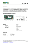
CT-4030 Wireless Control Jammer Operating Guide Confidential Document version 1.0 Dec, 2013 If you have any comments, please contact Email: [email protected] Disclaimer: Information in this document is subject to change without notice. No part of this publication may be reproduced, photocopied, stored in a retrieval system, or transmitted without the express prior written consent of Table of Contents 1. 2. 3. 4. 5. 6. Introduction .......................................................................................................................... How to Use this Operating Guide ........................................................................................ CT-4030 Users ..................................................................................................................... . CT-4030 Safety Standards .................................................................................................... The Product and Accessories................................................................................................ CT-4030 Installation ............................................................................................................. CT-4030 Operating ............................................................................................................... You are now ready to operating the jamming system. ................................................... 7. CT-4030 Packing .................................................................................................................. 1. Introduction This is the operating guide for the CT-4030 jammer unit from Jammers4u. This vehicle mounted jammer is used to block cell-phone downlinks for the following frequency ranges: 850 - 899 MHz:60W 925 - 965 MHz:60W 1795-1990 MHz:50W 2100 – 2180 MHz :50W Option: WiFi 2400-2500MHz: 30W GPS L1 1575MHz: 30W 130-180 MHz:50W 400-480 MHz:50W 4G 2620-2650MHz: 30W At the various frequency levels, the CT-4030 provides jamming including AMPS, N-AMPS, CDMA, GSM, DCS, TDMA, IDEN, UMTS, 4G LTE, 4G WiMax and VHF, UHF. The CT-4030 unit is installed with high performance Directional antenna and connected to a power supply. It then jams the signals transmitted by a base station, repeater, or an individual cellular phone at various frequencies. The CT-4030 is used in Jail or open space. When a cell-phone frequency is jammed, all communications through a cellular phone are not possible. These include, incoming calls, outgoing calls, SMS, picture sending. 2. How to Use this Operating Guide Before you use this operating guide, follow the below points: We advise you to read through the introductory sections on safety standards, the product, and accessories, so that you have some basic understanding of the product, before starting the installation. If you know about the unit accessories and their characteristics, you can move to the installation and operation chapter starting from page XX. However, the introductory material may still be useful as a reference. To operate the jammer using remote configuration from the notebook, follow the procedures starting on page XX To understand more about the technical features of the CT-4030 unit, refer to the Specifications chapter on page XX. 3. CT-4030 Users This operating guide is best suited for users in the military and police forces who wish to perform cell-phone jamming operations. To carry out operations with maximum safety and efficiency, it is best advised that more than one operator is available on hand. With some operations, such as carrying the unit in Pelican cases, it is mandatory that two or more personnel are available. This operating guide is also useful for technicians who wish to analyze and troubleshoot product operations. The troubleshooting and specifications sections on page XX should be most useful for these users. 4. CT-4030 Safety Standards Before using the CT-4030, please notice the following safety mentioned, and make sure you comply with local laws and regulations relating to radio transmittal. Failure to comply with these guidelines may be dangerous or illegal. In event of doubt, please consult your local Jammers4u distributor or Jammers4u before use. Handling and Transportation The Unit is heavy. Take maximum care handling it. Always put it firmly on a stable horizontal surface and prevent sliding. 5. The Product and Accessories The CT-4030 product consists of the following: Main unit that allows you to control jamming. The unit is housed in a Pelican case. Mandatory accessories that are used with the unit, including cables, antennas, Tripod. Jammers4u will automatically supply these items to you. (the switching power supplies has include main unit of internal) Optional accessories that depend on your own configuration needs. Jammers4u are able to supply these items on request. You will also need to supply your own equipment, including a notebook, as well as a spectrum analyzer to measure signal strength in the different frequency bands. The product is also packaged in carton boxes. Before assembling the jammer system, you must make sure that you have the unit and all accessories that you require. It is important that you not only check the equipment, but that you have some understanding of their functions before selecting an installation procedure: 5.1 Packaging Carton packaging is provided for the product. The CT-4030 unit itself is provided in one box, while the antennas & Tripod are provided in separate boxes. All cabling accessories are provided in the other boxes. 5.2 CT-4030 Unit The CT-4030 consists of a control unit that allows you to jam specific cellular frequencies. The unit consists of controls; and an aluminum chassis casing, with holes to provide ventilation. The central control panel that lets you perform the following: Power ON/OFF Select the RF power output of each modular. Check RF output power readings from the LED display Temperature over protection. VSWR over protection for each modular. The CT-4030 also houses individual module control units, for controlling jamming at specific frequency bands that are placed in the openings of the chassis casing. You can tell which module control unit handles which frequency band as it includes a Number-Code on the front of the module. 5.2.1 Locking the Unit A Pelican case can have a padlock attached to it in order to lock it for security purposes. 5.3 CT-4030 Accessories You will be provided with the following accessories when you purchase the CT-4030. You can purchase optional accessories from Jammers4u. All units and accessories have a 1 year warranty agreement. It is important that you not only check the accessories, but that you have some understanding of their functions before selecting an installation procedure: 5.3.1 Antenna Along with the CT-4030, antennas are provided for the different modules requested by the customer. Antennas connect to the unit and are used to transmit signals for jamming. Antennas are provided in separate boxes, where each box contains one antenna : Two Bands Antennas for cell phone modules Antennas for Wireless remote Control Base and Modules and Magnetic Base Cell phone Module Antennas The antenna consists of two rectangular panels. The antennas are constructed from glass fiber A specific antenna is used for a frequency band. You will know the frequency band of the antenna, as each antenna contains a Number sticker to indicate the band. Please see dimension in specs. Wireless Control Base and Module Antennas and Magnetic Base For wide-band modules, the following two antennas are used: Omni-directional antennas allow the jammer to jam signals from all directions. 5.3.2 RF Cable & Magnetic Base The RD214 RF coaxial cable as shown below lets you connect the CT-4030 to the antenna. It measures a maximum of Three or five meters. 5.3.3 AC Power Supply A standard AC power supply lets you provide power to the jammer when an AC power supply socket is available. CT-4030 uses an 110V or 240V AC power supply. It has Siwtch manualy 5.3.4 AC Power Cable An AC power cables lets you connect the jammer to the AC power supply. It must be used with the AC power supply. 5.3.5 Wireless Control Base (RS232 cable) 5.3.6 Software CD For performing jamming configurations from a notebook, you are provided with a software CD that you need to install on your own Notebook 5.4.1 UPS Backup System: DC to AC Inverter 3000W + 12V Car Battery The DC to AC Inverter + 12V Car Battery provides the jammer with continuous power. It can be used in both land and vehicle deployments. The UPS Backup power supply System provides the jammer with 110V or 220 Volts AC power. . 5.5 Self-Supplied Equipment To perform effective jamming, you are best advised to supply your own notebook, spectrum analyzer/mobile phone with Net Monitor. 5.5.1 Notebook You must supply your own standard notebook computer to control the CT-4030 unit remotely. You will also need a notebook in order to configure the jammer, for example, to perform lock-out functions of particular frequency bands. More information on performing operations using the notebook is described on page 30. 5.5.2 Spectrum Analyzer You should supply a standard spectrum analyzer kit including a monitor and antenna to measure dBm readings for the frequency band that you wish to perform jamming. You need to make sure that the spectrum analyzer can perform readings for the specific frequency band. 6. CT-4030 Installation and Operation The CT-4030 can be installed and operated at a suitable location on land. 6.1 Installation and Operation Workflow 6.2 Pre-Installation Checks If you wish to install the jammer for stationary use, you must make sure that you have the following accessories: CT-4030unit RF cable Antenna: Directional antennas for cell phone bands and Wirlees remote omni antennas AC cable / UPS cable DC to AC Inverter + 12V car Battery Wireless Remote Control Base and Magnetic Base Notebook or Destop computer Spectrum analyzer/mobile phone with Net Monitor 6.3 Selecting a Location When selecting a base station location, you need to consider the following factors: Distance of the jamming area from a base station, repeater, or individual cellphone Signal strength in the area In general, the further the distance from the base station or repeater, the weaker the signal. However, the signal strength can depend on factors such as the terrain of the area. For example, if the base station is positioned at a higher level from the jammer, such as on top of a hill, the jammer may receive a higher signal when it is positioned further away. It is not advised that you set up the CT-4030 in an indoor environment, as the total signal power generated when jamming is too high. 6.4 Measuring Signal Strength You can measure the signal strength in dBm for a selected frequency band when choosing a location by using a spectrum analyzer. Note: When checking signal levels by using a spectrum analyzer, make sure that the main CT-4030 unit is off. To check signal levels and jamming distance using a spectrum analyzer: 1. 2. 3. 4. 5. Go to a desired location. Connect an antenna to a spectrum analyzer. Connect the spectrum analyzer to a UPS or DC power source. Connect a spectrum analyzer monitor if necessary. Turn on the spectrum analyzer. 6. Set the spectrum analyzer to read the desired frequency band. 7. Read the dBm readings for the specific frequency band. Note: It is also possible to use spectrum analyzer software instead of a traditional spectrum analyzer. If so, make sure that a notebook is available with spectrum analyzer software. You are now ready to move to procedures on page XX for assembling the antenna 6.5 Assembling the Antenna Once you have decided on a location after taking consideration distance, signal strength, and terrain, you are ready to set up the antenna. When assembling antennas for stationary use, assembly either cellphone module antennas, wide-band antennas, or both. 6.5.2 Assembling Cell phone Module Antennas Cell phone module antennas should be mounted to an H-Frame and an extendable tripod. Extending the tripod is advantageous as better signal reception is usually when the antenna is placed at a greater height. Note: Make sure that you do not mount the stand in the following places: - On surfaces with water such as rivers - Areas of cliff erosion - Sandy surfaces Once you have assembled cellphone module antennas, follow the procedures below for assembling wide-band antennas or go to the procedures for connecting components on page XX 6.6 Connecting Components Once the antenna has been mounted, the power supply, and antenna can be connected to the CT-4030 unit. However, before connecting the unit to its components, you need to consider the following safety issues. 6.6.1 Safety Considerations Although the CT-4030 is placed in its own case, when open, you need to take care that the unit is not exposed to dust particles, water droplets, explosive chemicals, flames or flammable objects. Where elements such as water and dust are unavoidable, proper weatherproof covers must be supplied to the CT-4030 unit. 6.7. Procedure for Connecting Components To connect all antennas: 4 bands Driectional Antennas + Wireless Remote Omni Antenna with Magnetic Base To Setup Wireless Control Base with Desktop Computer or Notebook USB to RS232 Cable for Notebook (Need to install Driver CD RS232 to RS232 Cable for Desktop PC Wireless Remote RS232 to Desktop PC Antenna Connect to or Notebook To Install Jail Jammer System Software on Desktop Computer or Notebook 1. Copy all 4 files to Computer local folder like Jail System on desktop 2. Double Click Jail Jammer System Icon to execute the software 3. Program Open 4. Click “CONFIG Icon “ to setup COM Port # For Desktop PC, Normal is COM1 For Notebook, Normal is COM7 or 8 Can Change Name of Jammer Jammer U01 Jammer U02….. 5. Click “ Start Icon” to Start Checking all Jammer’s Status 6. Show all Online Jammer’s Status Once you have finished the procedures on connecting components, you are ready to operate the jammer and modules. Note: The RF cable can be stretched to a distance of 3 or 5 meters. 6.7 Operating the Jammer and Modules You will have performed the following: Set unit location Connected antenna to the jammer Connect jammer to components Setup Wireless Remote Base and Install Jail Jammer System on Computer Now you are ready to: Power up the jammer Adjust output power to control jamming Initialize Wireless Remote Control Program 6.7.1 Powering Up the Jammer Once components have been connected, the jammer is powered up. ****Note: Please make sure the following before you connect AC Power Cord**** 1, All Antennas connect tightly ( 5 antennas Cables) 2, All Output power Din Switch is Min Power Switch All Dins Down…min Output Power 3 Setup Wrieless Remote Control Base with Jail Jammer System Software To power up the jammer: 1. Plug Power Cord to AC. CT—4030 will turn on You have now powered up the jammer, follow the next procedure for adjusting output power. 6.7.2 Adjusting Output Power You can adjust output power from 1 Watts to Max Output Power (50 or 60 Watts). The output power you set depends on the signal strength and the distance between the jammer and base station/repeater/target phone. To adjust output power: Power Switch All Dins UP …Max Output Power 1st 2100-2175MHz 2nd 1800-2000MHz 3rd 920-965MHz 4th 850-895MHz 4th 850-895MHz 3rd 920-965MHz Hard Turn ON Switch 3rd Jammer ID: 3rd 2nd 1800-2000MHz 1st 2100-2175MHz Power Switch All Dins UP …Max Output Power On Software.. Operation ON is “Green “ for each Band You have now successfully set up the CT-4030 to jam signals. To perform further configurations from a notebook, such as Turn ON/OFF each band, each jammer o the whole jammer system, follow the procedure below for initializing remote control software. 7. Wireless Control Software Operations 1, To Check the Jammer Status Click “ Start Icon”.. Show All Online Jammers….. Jammer U01 ID 01 is ON, with min output power (Operation OFF). 2, To Turn ON/OFF each Band or the Jammer Click “Check Status” to update the jammer Status now “ Power ON” to Turn ON and “ Power Off” to Turn Off the Jammer. Double Click.. Turn ON/OFF each Band “Power 3, To Turn ON/OFF The Whole System Jammers Click “ System Power ON” to Turn ON and “ System Power Off” to Turn Off the all Jammers. UP or DOWN the whole Jammer System…