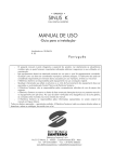
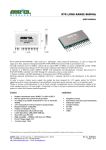
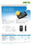
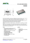
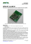
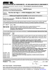
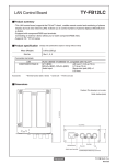
1
RX CLASS1 869
---------------------------------------------------------------------------------------------------------------------------------------------------
User manual
DESCRIPTION
The RX-CLASS1 869 receiver has been designing to satisfy the stringent requirements of applications
operating in Class 1 where radio communication may involve physical risks for the human person (as stated
by European standards ETSI EN 300-220-2). These applications include social alarms, devices for help calls
for people who live alone. They can operate in the VHF and UHF bands, on ranges reserved for Social
Communications Alarms. In particular CLASS1 RX-869 operates in the band 869.2 to 869.25 MHz on 2
different channels with 25KHz narrowband and electrical features complying with the ETSI EN 300220-2
v2.3.1. (2010-02) in class 1.
MECHANICAL DIMENSIONS AND PIN-OUT
Pin-Out
Applications
1) +Vcc
2) GND
3) RF Input (50 ohm)
7) GND
10) Power-Down
11) GND
12) Data-Rate
13) RSSI Out
14) Data Out
15) Radio channel selection
Social alarms
Nurse call
Personal Security
Smoke detector
Electrical limits
Voltage supply
Input voltage
Output voltage
Operating temperature range
-0,3V +6V
-0,3V ÷ Vcc+0,3V
0V ÷ Vcc
-10°C ÷ +55°C
Technical features are subjected to change without notice. AUR°EL S.p.A doesn't assume any responsability for damages due improper use.
--------------------------------------------------------------------------------------------------------------------------------------------------------------------AUREL S.p.A. Via Foro dei Tigli, 4 - 47015 Modigliana (FC) – ITALY
22/02/12 - Rev.B
Page 1 of 9
Tel.: +39.0546.941124 Fax: +39.0546.941660
http://www.aurelwireless.com - email: [email protected]
RX CLASS1 869
---------------------------------------------------------------------------------------------------------------------------------------------------
User manual
CONNECTION PIN DESCRIPTION
Pin 1
+V
Connection to voltage supply: +3V ÷ +5,5V
Pin 2
Ground
Connection to GND
Pin 3
Antenna
Antenna connection, impedance 50 ohm.
Pin 7
Ground
Connection to GND
Pin 10
Power Down
Pin 11
Ground
Digital input for the switching on of the receiver.
Low logic level or pin not connected: receiver switches off (power-down
mode)
High logic level: receiver switches on
(for details see paragraph “Power-down working”)
Connection to GND
Pin 12
Data-rate
Pin 13
Pin 14
RSSI Out
Data output
Pin 15
Radio channel
selection
Data-rate digital input
Low logic level: as input data-rate (range : 50 bps ÷ 2Kbps)
High logic level: data-rate 1kbs.
(For details see paragraph “Data-rate selection”)
Analogue output for the measurement of the received radio signal level.
Receiver digital data output.
Digital input to set the radio channel
Low logic level or pin not connected: reception of frequency 869,2325MHz
High logic level: reception of frequency 869,2175MHz
(for details see paragraph “Selection of radio channel”)
HOW IT WORKS
CLASS1 RX-869 integrates a new technology able to achieve high performance selectivity of the radio
channel without using the traditional quartz filters so far implemented in the narrow-band super heterodyne
receivers. The front-end circuit consists in a low noise amplifier with high gain, controlled by an automatic
gain circuit with 50 dB dynamic and an high immunity mixer to the intermodulation. A fractional PLL circuit
controls a high-performance low noise VCO which allows you to select two different radio frequencies
through the pin 13: 869.2125 MHz (pin.13 open or GND) and 869.2375 MHz (pin.13 connected to Vs) .
The FSK demodulator allows to choose two different data rate by PIN12:
1kbs (PIN12 to Vs) and transparent (open or GND pin 12). RX-869 integrates CLASS1 an u-controller that
manages all radio circuits and power-down mode by PIN10.
It’s available an analogue signal as RSSI to the 13 pin with voltage level proportional to the received radio
signal.
Technical features are subjected to change without notice. AUR°EL S.p.A doesn't assume any responsability for damages due improper use.
--------------------------------------------------------------------------------------------------------------------------------------------------------------------AUREL S.p.A. Via Foro dei Tigli, 4 - 47015 Modigliana (FC) – ITALY
22/02/12 - Rev.B
Page 2 of 9
Tel.: +39.0546.941124 Fax: +39.0546.941660
http://www.aurelwireless.com - email: [email protected]
RX CLASS1 869
---------------------------------------------------------------------------------------------------------------------------------------------------
User manual
Technical features
Min
Vs voltage supply
Current supply RX = ON
Pin 10 (pwdn) = 1
Pin 1 e 15 = +Vs
Current supply in power-down mode
Pin 10 (pwdn) = 0
Pin 1 e 15 = +Vs
Center frequency reception
Pin 15 = 0 o NC
Center frequency reception
Pin 15 = 1
RF sensibility
FSK modulation e ∆F
Bandwidth IF a –3dB
Adjacent channel selectivity
Receiver saturation on adjacent channel
Blocking test ±2MHz
Blocking test ± 10MHz
Frequency image rejection
Output square wave
Setting:
Pin 12 = 0 o not connected (Free mode)
Output square wave
Setting:
Pin 12 = 1 (1kbps)
RSSI analogue output (pin 13)
RSSI output impedance (pin 13)
Output low logic level (pin 14)
Output high logic level (pin 14)
Input high logic level (pin 10,12)
Input low logic level (pin10,12)
Spurious RF emission antenna
Switching-on time
Setting:
(pin 1, 10, 15) = 0 → 1
Switching-on time PWRDN → RX-ON
Usage:
(pin 1, 15) Vcc = 1
(pin10) PWDN = 0 → 1
Operating temperature range
Dimensions
Typical
3
Max
Unit
5,5
V
40
mA
3
-113
4
-2%
MHz
869,2125
MHz
-115
5
10
54
95
100
100
40
-117
6
dBm
KHz
KHz
dB
dB
dB
dB
dB
See
See
See
See
See
1
2
KHz
See note 6
500
+2%
Hz
3
V
Kohm
V
V
V
V
dBm
1
gnd+0,4
Vs-0,4
Vs-0,4
0,4
-60
-10
uA
869,2375
0
Notes
note
note
note
note
note
1
1
3
3
2
See note 4
See note 4
100
ms
See note 5
100
ms
See note 5
+55
45,7 x 20 x 3,5 mm
°C
NOTE 1: Test carried out as shown in 8.3 paragraph of the normative ETSI EN 300 220-1 V2.3.1
NOTA 2: Test carried out as shown in 8.5 paragraph of the normative ETSI EN 300 220-1 V2.3.1
NOTA 3: Test carried out as shown in 8.4 paragraph of the normative ETSI EN 300 220-1 V2.3.1
NOTA 4: Values obtained with a maximum load of 10KΩ.
NOTA5: Switching-on time means the time requested from the receiver to rich the technical features shown above.
NOTA 6: This setting not allow to be under normative (note 1),it’s usefull for test.
Technical features are subjected to change without notice. AUR°EL S.p.A doesn't assume any responsability for damages due improper use.
--------------------------------------------------------------------------------------------------------------------------------------------------------------------AUREL S.p.A. Via Foro dei Tigli, 4 - 47015 Modigliana (FC) – ITALY
22/02/12 - Rev.B
Page 3 of 9
Tel.: +39.0546.941124 Fax: +39.0546.941660
http://www.aurelwireless.com - email: [email protected]
RX CLASS1 869
---------------------------------------------------------------------------------------------------------------------------------------------------
User manual
Power-down function:
RX-CLASS1 869 has a power down pin that allows a very fast switching off and switching on.
POWER_DOWN mode: Setting to the low logic level Pin 10, the receiver is switches-off with 3uA of
current consumption.
Reception mode: Setting PWRDN pin 10 from low to high logic level the receiver switches on in 100ms,
ready to receive as shown the technical features.
Time diagram
POWER-DOWN → RX
Valid Reception
Data Output
Radio channel selection
The RX-869 CLASS1 works in 869.2 MHz ÷ 869.25 MHz band assigned by ETSI for the exclusive use of
applications on social alarms across Europe.
EN 300 220-1 v2.3.1 normative also requires the use of 2 channels spaced 25 KHz.
CLASS1 The RX-869 can operate on both frequencies using the pin 13 called "radio channel".
Pin.15 logic value
+Vs
GND
X
Reception frequency (MHz)
869,2125
869,2375
869,2375
NOTE1: The change of the channel is achieved by power-down pin 10, setting from low logic level to high logic level.
Technical features are subjected to change without notice. AUR°EL S.p.A doesn't assume any responsability for damages due improper use.
--------------------------------------------------------------------------------------------------------------------------------------------------------------------AUREL S.p.A. Via Foro dei Tigli, 4 - 47015 Modigliana (FC) – ITALY
22/02/12 - Rev.B
Page 4 of 9
Tel.: +39.0546.941124 Fax: +39.0546.941660
http://www.aurelwireless.com - email: [email protected]
RX CLASS1 869
---------------------------------------------------------------------------------------------------------------------------------------------------
User manual
During the normal reception mode the changing will be ignored.
NOTE2: For different applications from “Social Alarm”, its’ possible modify the reception frequency channels.
Data-rate selection
pin.12 logic value
+Vs
GND
X
Data-rate values
1kbps
50-2000Hz range of free data rate output
50-2000Hz range of free data rate output
The RX-869 CLASS1 internally uses a post-demodulator circuit that improves the performance in terms of
sensitivity and adjacent channel rejection, this at the expense of less flexibility in the format of data that the
receiver is able to handle.
The 1Kbps data-rate uses a rebuilder of the output data with 1ms samplings, therefore the kind of data that
the receiver can analyze must have a maximum time length of 1ms +-2%, for each single bit ( both lengths
as low bit or high bit) . It’s possible to take frame time double, triple or quadruple time longer. he main
advice is to realize a Manchester protocol with 2ms bit time length. The 1Kbps choice is not a bind, on
demand it’s possible customize this parameter in the range of 0,5 kbps and 3 kbps.
In order to figure out this matter, below is shown the timing diagram. In the opposite the “free modality”
(open 12 pin) allows to receive each kind of data between 50Hz and 2KHz at the expense of the overcoming
of the regulation. It is set in order to allow the evaluation test , as: test with an existing transmitter with a
own protocol.
In the final application, the use of the post-demodulator (pin 12 = + Vs) is bound to exceed the ETSI EN
300 220-1 v2.3.1 for class 1.
NOTE: Setting of the data-rate value is achieved after the forcing of the power-down (Pin 10 from low to
high). During normal operation, the control pin data rate will be ignored.
Technical features of the output data with 1Kbps data-rate
MANCHESTER Code
Technical features are subjected to change without notice. AUR°EL S.p.A doesn't assume any responsability for damages due improper use.
--------------------------------------------------------------------------------------------------------------------------------------------------------------------AUREL S.p.A. Via Foro dei Tigli, 4 - 47015 Modigliana (FC) – ITALY
22/02/12 - Rev.B
Page 5 of 9
Tel.: +39.0546.941124 Fax: +39.0546.941660
http://www.aurelwireless.com - email: [email protected]
RX CLASS1 869
---------------------------------------------------------------------------------------------------------------------------------------------------
User manual
Temperature chart TBD
Pin.13 “RSSI” diagram
Pin.13 RSSI gives an analogue signal proportional to the received radio signal. The voltage range goes from 0 to 3 V
maximum, 1K of output impedance and 90 dB of dynamic radio signal. It’s available with incoming radio signal with a
time length higher of 1 second and updated each second. In picture number 1 it’s showed the RSSI output voltage
diagram according to RF input power. The diagram is obtained applying to the RF input (pin3) of the receiver a RF
generator modulated in FSK with 0,5 KHz square wave and with an index modulation of 3KHz.
RSSI OUTPUT
3
2,5
]
V
[ 2
l
e
v
e
L 1,5
I
S
S
R 1
0,5
0
-115 -105
-95
-85
-75
-65
-55
-45
-35
-25
-15
Input Power[dBm]
Picture 1: RF(dBm) input diagram according to the RSSI output(Volts)
Technical features are subjected to change without notice. AUR°EL S.p.A doesn't assume any responsability for damages due improper use.
--------------------------------------------------------------------------------------------------------------------------------------------------------------------AUREL S.p.A. Via Foro dei Tigli, 4 - 47015 Modigliana (FC) – ITALY
22/02/12 - Rev.B
Page 6 of 9
Tel.: +39.0546.941124 Fax: +39.0546.941660
http://www.aurelwireless.com - email: [email protected]
RX CLASS1 869
---------------------------------------------------------------------------------------------------------------------------------------------------
User manual
Delta sensitivity [dB]
2
0
-2
-4
-20
0
20
40
60
Temperature [°C]
Picture 1: Diagram of the delta sensitivity depending on temperature(°C)
Center freq. Vs temp.
TBD
TEMPERATURE DIAGRAMS TBD
Technical features are subjected to change without notice. AUR°EL S.p.A doesn't assume any responsability for damages due improper use.
--------------------------------------------------------------------------------------------------------------------------------------------------------------------AUREL S.p.A. Via Foro dei Tigli, 4 - 47015 Modigliana (FC) – ITALY
22/02/12 - Rev.B
Page 7 of 9
Tel.: +39.0546.941124 Fax: +39.0546.941660
http://www.aurelwireless.com - email: [email protected]
RX CLASS1 869
---------------------------------------------------------------------------------------------------------------------------------------------------
Manuale d’uso
Device usage
In order to take advantage of the performances described in the technical features and to comply with the
operating conditions which characterize the certification, the receiver has to be fitted up on a printed circuit,
considering what follows:
Voltage supply:
1. The receiver must be supplied by very low voltage security source protected against short circuits.
2. Maximum voltage variation admitted: ± 0.3 V.
3. De-coupling, next to the receiver, by means of a ceramic capacitor of minimum 100.000 pF value.
Ground:
It must surround in the better way the welding area of the receiver. The circuit must be achieved in double
layer, with throughout vias to the ground planes, approximately each 15 mm. It must be properly
dimensioned in the antenna connection area, in case a radiant whip antenna is fitted in(and area of
approximately 50 mm is suggested).
Fig.2 Lay-out advised for a correct working of the receiver
50 Ohm Line:
1. It must be as shorter as possible.
2. 1,8 mm wide for 1 mm thick FR4 printed circuits and 2,9 mm wide for 1,6 mm thick FR4 printed circuits.
On the same side it must be kept 2mm away from the ground.
3. On the opposite side a ground circuit area must be present.
Antenna connections:
It may be utilized as the direct connection point for the radiating whip antenna. It is deeply suggested to put
a 100nH inductance from pin 3 to ground in order to protect the device from the electrostatic discharges.
It can bear the connection of the central wire of a 50 ohm coaxial cable. Be sure that the braid is welded to
the ground in a close point.
Antenna
Technical features are subjected to change without notice. AUR°EL S.p.A doesn't assume any responsability for damages due improper use.
--------------------------------------------------------------------------------------------------------------------------------------------------------------------AUREL S.p.A. Via Foro dei Tigli, 4 - 47015 Modigliana (FC) – ITALY
22/02/12 - Rev.B
Page 8 of 9
Tel.: +39.0546.941124 Fax: +39.0546.941660
http://www.aurelwireless.com - email: [email protected]
RX CLASS1 869
---------------------------------------------------------------------------------------------------------------------------------------------------
Manuale d’uso
1. A whip antenna, 80 mm long and approximately 1 mm dia, brass or copper wire made, must be
connected to the RF input of the receiver.
2. The antenna body must be kept straight as much as possible and must be free from other circuits or
metal parts (5cm minimum suggested distance).
3. It can be utilized both vertically or horizontally (the previous is highly suggested), providing that
connection point between antenna and receiver input is surrounded by a good ground plane.
N.B: As an alternative to the above mentioned antenna it is possible to use the whip model manufactured
by Aurel (see related Datasheet and Application Notes).
By fitting whips too different from the described ones, the EEC Certification is not assured.
Other components:
1. Keep the receiver separate from all other components of the circuit (more than 5mm).
2. Keep particularly far away and shielded all microprocessors and their clock circuits.
3. Do not fit components around the 50 Ohm line. At least keep them at 5 mm distance.
4. If the antenna connection is directly used for a radiating whip connection, keep at least a 5 cm radius free
area. In case of coaxial cable connection, 5 mm radius will suffice.
REFERENCE NORMATIVE
The RX CLASS1 869 is approved by CE and in particular satisfies the European normative ETSI
EN 300 220-2 V2.3.1 in class 1 and EN 301 489-1 V1.4.1 in class 1. The product was tested in
according with EN 60950 normative and it’s usable fitted in an isolated housing to ensure the
above normative. The receiver must be supplied by very low voltage security source against the
short circuits. Usage of receiver module is foreseen fitted in the housing which ensure the
agreement of EN 61000-4-3 normative not directly applicable to the module itself. In
particular, it’s at the user’s care the isolating of the extern antenna connection and antenna
too, in fact the RF output of the receiver is not able to directly bear electrostatic charges
foreseen in the above normative.
Technical features are subjected to change without notice. AUR°EL S.p.A doesn't assume any responsability for damages due improper use.
--------------------------------------------------------------------------------------------------------------------------------------------------------------------AUREL S.p.A. Via Foro dei Tigli, 4 - 47015 Modigliana (FC) – ITALY
22/02/12 - Rev.B
Page 9 of 9
Tel.: +39.0546.941124 Fax: +39.0546.941660
http://www.aurelwireless.com - email: [email protected]