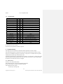
1
Gertbot Rev 2.3-September-2014 Gertbot Rev 2.3, 8 September2014 The Gertbot is a motor/power controller board for the Raspberry-Pi. The strength of the board is that it has its own CPU which frees up the Raspberry-Pi from a lot of intense computations and will take care of all the real time requirements. All you have to do is give it high level commands. Like: Board 2, Motor 1, take 2432 steps at 67 Hz. Even giving those commands is done for you using the free GUI which comes with it! Hardware features: Four H-bridges 8V-30V, 2.5A. Bridges can be re-configured for 2x 5A or 1x 10A. Two open drain outputs 30V, 3A. Power full 64MHZ ARM Cortex-M3 processor RS232 connects direct to the Raspberry-Pi or other serial interface. Cascade port to control up to four boards at a time. 20-pin connector programmable for: o Automatic motor end-stop o Four 12-Bit ADC ports o Two 12-bit DAC ports o 8-16 general purpose I/O Software controllable features: Brushed1 motors: o Control direction o Speed control PWM 10Hz-10KHz, 0-100%. o Soft start 0.1sec .. 5 seconds prevents in-rush current o Stop on switch hit. Stepper motors: o Take X-steps in either direction o Step speed 0.06 Hz .. 5KHz. o Stop on switch hit. Digital Command Control (model train control): o Can send any DCC command 3..6 bytes o Programmable pre-amble length and repeat count Short-circuit or high temperature error detection On error, keep running, stop motor, stop board or stop all boards I/O pins programmable functions Emergency stop, halts whole system. The board comes with drivers, example code and a GUI all complete with source code. Depending how fast you can screw the wires down, you can have your motors running in a few minutes! 1 I used the term ‘brushed motor’ to indicate the standard DC brushed motors. You find those in most toys. 1 Copyright © 2014 Fen Logic Ltd. The copyright is on the manual as well as the instruction set Gertbot Rev 2.3-September-2014 The board can also be used to drive other power electronics like LEDS, relays etc. Using a 30V supply and 2mA LEDS you can drive three sets, each of ~12500 RGB LEDS, using the boards PWM feature to control the colour. READ THE MANUAL! The most difficult part of controlling motors has been taken care of by the software running on the Gertbot. Instead of directly having to manipulate the motors, you send high-level commands to the Gertbot which will execute them. But this does mean that you have to learn what those commands are. Therefore you should read the manual. Quick start: For those of you who want to start quickly: there is a Gertbot GUI which you can use to control every feature of the Gertbot. There is a separate Gertbot GUI manual which guides you through the controls but it refers to this manual to explain the details of operation. Advanced: The Gertbot Advanced guide helps you with cascading boards, operate bridges in parallel to double or quadruple the maximum current. It also tells you how to upload new software versions or how erase the current program and put your own software on the board. 2 Copyright © 2014 Fen Logic Ltd. The copyright is on the manual as well as the instruction set Gertbot Rev 2.3-September-2014 Contents 0 I want to use it NOW! ...................................................................................................................... 5 1 Overview: ...................................................................................................................................... 13 1.1 LEDs ..................................................................................................................................... 13 2 Connecting things up ..................................................................................................................... 14 2.1 Connecting Gertbot to a Raspberry-Pi .................................................................................... 14 2.2 Connecting motors. ................................................................................................................ 14 2.3 Connecting stepper motors. .................................................................................................... 16 2.4 Connecting motor power ........................................................................................................ 16 2.5 Connecting end-stops. ............................................................................................................ 17 2.6 Connecting Open drain output ................................................................................................ 18 2.7 Connecting to other then Raspberry-Pi ................................................................................... 19 2.7.1 Connect to J12 (cascade connector) ................................................................................ 19 2.7.2 Connect to J6 (Pi connector) ........................................................................................... 20 2.7.3 Connect to J14 (Not mounted) ........................................................................................ 20 3 Commands..................................................................................................................................... 21 3.1 Identifier ................................................................................................................................ 21 3.2 Values .................................................................................................................................... 22 3.3 Making commands ................................................................................................................. 22 3.4 Command table ...................................................................................................................... 23 4 Command details ........................................................................................................................... 23 4.1 Read version .......................................................................................................................... 23 4.2 Operation mode...................................................................................................................... 24 4.3 End-stop & short/hot set up .................................................................................................... 26 4.4 DC/Brushed Pulse Width Modulation Motor Frequency ......................................................... 28 4.5 Brushed Motor Duty Cycle..................................................................................................... 28 4.6 Start/stop Brushed Motor ....................................................................................................... 29 4.7 Read error status .................................................................................................................... 30 4.8 Stepper motor take steps......................................................................................................... 31 4.9 Stepper Motor Step Frequency ............................................................................................... 32 4.10 Stop all .................................................................................................................................. 33 4.11 Switch open drain .................................................................................................................. 33 4.12 Set DAC ................................................................................................................................ 33 4.13 Read ADC ............................................................................................................................. 33 4.14 Read I/O ................................................................................................................................ 34 4.15 Write I/O ............................................................................................................................... 34 4.16 Set I/O ................................................................................................................................... 35 4.17 Set ADC/DAC ....................................................................................................................... 36 4.18 Board configure ..................................................................................................................... 36 4.18.1 Board Synchronous command mode. .............................................................................. 36 4.18.2 'Attention' signal mode. .................................................................................................. 37 4.18.3 Stop on error. ................................................................................................................. 37 4.18.4 Board configure command overview............................................................................... 37 4.19 Read board status ................................................................................................................... 37 3 Copyright © 2014 Fen Logic Ltd. The copyright is on the manual as well as the instruction set Gertbot 4.20 4.21 Rev 2.3-September-2014 Clear errors?? ........................................................................... Error! Bookmark not defined. Read motor status ................................................................................................................... 38 5 Digital Command Control .............................................................................................................. 39 5.1 DCC command ...................................................................................................................... 40 5.2 DCC configure ....................................................................................................................... 40 5.3 Connecting it up. .................................................................................................................... 41 6 Operating details ............................................................................................................................ 41 6.1 End-stops ............................................................................................................................... 41 6.2 Halt ........................................................................................................................................ 43 6.3 Frequency settings ................................................................................................................. 43 6.3.1 Jitter. .............................................................................................................................. 43 6.3.2 Accuracy. ....................................................................................................................... 43 6.4 Synchronous operation ........................................................................................................... 44 6.4.1 Direct commands............................................................................................................ 44 6.4.2 Synchronous commands ................................................................................................. 46 7 Motor error .................................................................................................................................... 47 7.1 Reaction to an error ................................................................................................................ 47 7.2 Oscillation.............................................................................................................................. 48 7.3 Brushed motor start/stop ........................................................................................................ 48 8 Appendix A: error codes. ............................................................................................................... 50 9 Software. ....................................................................................................................................... 52 9.1 Gertbot Gui. ........................................................................................................................... 52 9.2 Gertbot C-drivers. .................................................................................................................. 52 9.3 Gertbot Python-drivers. .......................................................................................................... 52 9.4 Gertbot DCC GUI. ................................................................................................................. 52 10 Appendix B: Technology. .............................................................................................................. 53 10.1 DC voltage. ............................................................................................................................ 53 10.2 AC voltage. ............................................................................................................................ 53 10.3 H-bridge. ............................................................................................................................... 54 10.4 DC Brushed motor. ................................................................................................................ 55 10.5 Stepper motor......................................................................................................................... 56 10.5.1 Connections.................................................................................................................... 56 10.5.2 Mechanics ...................................................................................................................... 57 10.5.3 Rotor hold. ..................................................................................................................... 57 10.6 Inductors. ............................................................................................................................... 58 10.6.1 Switching it on. .............................................................................................................. 58 10.6.2 Switching it off. .............................................................................................................. 59 4 Copyright © 2014 Fen Logic Ltd. The copyright is on the manual as well as the instruction set Gertbot 0 Rev 2.3-September-2014 I want to use it NOW! If you are like a lot of engineers you don’t want to read a manual, you want to get started NOW. I can’t recommend that but this chapter might limit the damage if you still want to do so. Please use the following steps: 1. Connect a DC-brushed motor or stepper motor to the Gertbot. Also connect a power supply for your motors to the Gertbot. See §2 Connecting things up for how to do that. (From here the instructions assumes you have connected a DC motor to contacts A1,A2 or a stepper motor to contacts A1,A2,B1,B2) 2. Plug the Gertbot board on top of a Raspberry-Pi board which is powered down. Then boot the device. (On a B+ make sure to plug the board on GPIO pins 1-26.) 3. Login and download the software: git clone git:://github.com/<TODO> (You might want to make a directory to put all the Gertbot data into) 4. If you have not started the X-windows system yet, do so now: startx 5. Open a terminal window and go to the directory where you have cloned the Gertbot GUI software. Type ./gertbot (That is dot-slash-gertbot). (You may get a warning that your UART is not available. If so follow the instructions to enable the UART.) After that you see this: 5 Copyright © 2014 Fen Logic Ltd. The copyright is on the manual as well as the instruction set Gertbot Rev 2.3-September-2014 (The “Com..” is only present if you run the gui under windows) 6. Press the Connect button. A log window will pop-up and show the search for boards. Default from the factory the board has ID 0 so you should see this: 6 Copyright © 2014 Fen Logic Ltd. The copyright is on the manual as well as the instruction set Gertbot Rev 2.3-September-2014 On the right hand side is the log windows which we will ignore for now. 7. Use the control under “Motor 0” to select the operating mode. For There are 6 modes but for now select DC/brushed for a DC or brushed motor select: DC/brushed For Step Gray Off for a stepper motor select: Step Gray: 7 Copyright © 2014 Fen Logic Ltd. The copyright is on the manual as well as the instruction set Gertbot Rev 2.3-September-2014 8 Copyright © 2014 Fen Logic Ltd. The copyright is on the manual as well as the instruction set Gertbot Rev 2.3-September-2014 8. For DC/brushed motors you see this: You can now play with the buttons and your motor should run. 9 Copyright © 2014 Fen Logic Ltd. The copyright is on the manual as well as the instruction set Gertbot Rev 2.3-September-2014 Formatted: Right: 11.26 cm If you have a big motor the overcurrent protection might kick in. (This can be so fast so you will not notice it. All you find is that your motor does not start). If so press the “More” button and set the Ramp-Up speed to 1 second: (See §7.3 Brushed motor start/stop for details about that) 10 Copyright © 2014 Fen Logic Ltd. The copyright is on the manual as well as the instruction set Gertbot Rev 2.3-September-2014 9. For stepper motors you see this: You can now play with the buttons and your motor should take 10 steps. InYou can change the beginning I would advise you to stop with no power‘Frequency’ and ‘Steps’ values on the stator. Usescreen to see what they do. 11 Copyright © 2014 Fen Logic Ltd. The copyright is on the manual as well as the instruction set Gertbot Rev 2.3-September-2014 Your stepper motor will have a maximum frequency above which it does not work reliable anymore. If your stepper motor is ‘rattling’ or only moves back-and-forth you have either connected the button to do that.wires wrong or one of your connections is failing. For more information about the Gertbot Gui read the manual: Gertbotgui.pdf Gertbot-Gui document. 12 Copyright © 2014 Fen Logic Ltd. The copyright is on the manual as well as the instruction set Formatted: Space Before: 0 pt, After: 0 pt, Line spacing: single Gertbot 1 Rev 2.3-September-2014 Overview: The boards consist of: A Central Processing Unit (CPU) Four H-bridges each 2.5A Two open drain outputs Two Digital-to-Analog converters (in CPU) Four Analog-to-Digital converters (in CPU) 10 general purpose input/output ports A UART connection A cascade port cascade Pi 5V uart CPU 3V3 ODx H H H H + A1 A2 B1 B2 + C1 C2 D1 D2 2xDAC 4xADC 10xI/O The four H-bridges can be used to control either four brushed motors or two stepper motors or two brushed and one stepper motor. You talk to the board using the UART (serial port) which must be set to 57600 baud, 8 bits 1 start, 1 stop bit, no parity. The Gertbot is controlled by sending commands over the UART port. There are commands to select what type of motors you have (brushed or stepper or a mixture). There are commands to run your motors, to specify when they should stop, to control the relays, read the ADC, set the DAC and a lot more. There is an expansion connector which allows you to connect up to four Gertbot boards in parallel. This gives you control over maximum 8 stepper motors or 16 brushed motors or various mixtures of both. 1.1 LEDs The board has four LEDs labeled as D5, D6, D7 and D8. At the moment only three of those are used: D8: D7: D6: D5: Heartbeat. Slowly blinking. Indicates the main system loop is running. Error. Fast blinking. Indicates there are errors in the error queue. Reading the errors from the queue (using the read error command) will stop the blinking. Halt. Steady on. Indicates the HALT line is active. Currently unused. 13 Copyright © 2014 Fen Logic Ltd. The copyright is on the manual as well as the instruction set Gertbot 2 2.1 Rev 2.3-September-2014 Connecting things up Connecting Gertbot to a Raspberry-Pi You plug the board on top of a raspberry-Pi. If you want to connect more than one board (cascade) please see the chapter in the ‘Gertbot advanced guide’. Rev A or B: The board has 26 pins as has the Gertbot: Raspberry-Pi B with Gertbot. Revision B+: The board goes on the outside 26 pins: Raspberry-Pi B+ with Gertbot. You will find that if you do not plug it in the right way. e.g. misalign by one pin , the board will bump against the Ethernet connector. 2.12.2 Connecting motors. The contacts for the motors are identified on the board using the notion A1, A2, B1, B2, C1, C2, D1, D2. A motor coil is always connected between X1 and X2. Thus between A1 and A2, B1 and B2 etc. 14 Copyright © 2014 Fen Logic Ltd. The copyright is on the manual as well as the instruction set Gertbot Rev 2.3-September-2014 Looking at the top of the board you get these connections: Gertbot Top view. In order to connect motors and power supplies use the following diagram: Gertbot Top view. DC/brushed motors Gertbot Top view. Stepper motors Notice that there is only one ground (blue) but the top outputs (A/B) and the bottom outputs (C/D) can have a different power supply. 15 Copyright © 2014 Fen Logic Ltd. The copyright is on the manual as well as the instruction set Gertbot Rev 2.3-September-2014 If you ever forget and don’t have this manual available: At the bottom of the board you find a diagram which shows where to connect the motor coils and the power supplies. Gertbot BOTTOM VIEW. 2.22.3 Connecting stepper motors. Brushed motors have a high impedance and you can connect a brushed motor direct to the board. This is not the case with a lot of stepper motors! Beware! Some stepper motors may need series resistors to connect them to the board. The controller needs a minimum of 8V to work. If your stepper motor requires less voltage you must add series resistor. If you connect up a stepper motor you will need to use a pair of connections. Thus a stepper motor connects to A1 & A2 and B1 & B2. Most likely your stepper motors has four or six wires. For details about stepper motors see chapter 10.5 Stepper motor. 2.32.4 Connecting motor power For a motor to run you must connect an external power supply. The motor controllers should be connected to a power source between 8 and 18Volt. For safe operation do not connect more than 18volts!! The board can withstand operating voltages up to 30V but anything above 18V can cause dangerous voltage levels to appear on the motor output pins. The bridge controllers need a minimum of 8V. If the input voltage is below 8V the controller will refuse to work. The power is connect with the plus connected to pin VAB or VCD. The ground goes to the Gnd 16 Copyright © 2014 Fen Logic Ltd. The copyright is on the manual as well as the instruction set Gertbot Rev 2.3-September-2014 connections. You can use a different voltage for VAB as for VCD, but all grounds of the board are connected together. Again at the bottom of the board you find a diagram which shows the power connections connected to a battery symbol. If you have a motor for a voltage less than 8volts you can try to connect it using a series power resistor. This will work for stepper as well as brushed motors. 2.42.5 Connecting end-stops. To connect end-stops you have to add a contact between one of the EXT pins and ground. You can use a mechanical switch or an optical switch. As each EXT pins has a pull-up resistor of 4700 Ohms to the controller’s 3.3 volt supply you only need to connect a switch between the pin and ground. These are the J3 pins which can be programmed as end-stop: Gertbot end-stop pins. Looking at the pins above the end-stops are assigned as follows: Motor 3:B Motor 2:B Motor 3:A Motor 2:A Motor 1:B Motor 0:B Motor 1:A Motor 0:A As stated all you need is a switch from the pin to ground. The following diagram shows how to connect all four B end-stop switches: You can connect a switch which is normally open and gets closed if the end-stop position is reached. In that case you must program the end-stop as active low. 17 Copyright © 2014 Fen Logic Ltd. The copyright is on the manual as well as the instruction set Gertbot Rev 2.3-September-2014 Alternative you can connect a switch which is normally closed and gets opened if the end-stop position is reached. In that case you must program the end-stop as active high. This is the preferred way of connecting an end-stop. If you use end-stops you MUST make sure your motor’s rotational direction is correct. The simplest way is to use the GUI and use the button of the GUI to make the motor move into the direction of end-stop A. If the motor goes into the opposite direction swap your motor wires around or swap your end-stop wires around. Also test your end-stop. There are two ways to do this: 1. Set the motor moving, operate the end-stop e.g. with a finger and check that the motor stops. 2. Operate the end-stop and check that the motor refuses to start in that direction If it does not work blame your circuit, not the Gertbot as that has been thoroughly tested! Did you connect to the right 'ext' pin, did you set the correct end-stop mode and polarity? 2.52.6 Connecting Open drain output The Gertbot has two open drain ports. The switch element is an NMOSFET. Each can switch 30V 3A. The following picture shows the open drain connections: Gertbot open drain connections. For those who are no familiar with open drain connections: An open drain is like a switch. But you can only switch DC currents and you must connect the plus to the drain pin (because the switch is an NMOSFETOD0 or OD1). As you can see from the diagram above, there is no power available at the output. For an open drain output to work, the user must provide an external power source. The open drain output does nothing more than provide a path with a very low resistance to ground when it is switched on. There is no protection on the open drain outputs. So the board will get damaged if you exceed the current or voltage specification. MOSFETS have the notorious habit of a large capacitive coupling from 18 Copyright © 2014 Fen Logic Ltd. The copyright is on the manual as well as the instruction set Gertbot Rev 2.3-September-2014 the drain to the gate. To prevent capacitive voltage spikes from blowing up the controller there is RC filtering between the gate and the controller. However there is no guarantee that it will protect under all circumstances. 2.62.7 Connecting to other then Raspberry-Pi The Gertbot board takes it commands in the format offrom a serialstandard UART stream. (UART stands for Universal Asynchronous Receive Transmit). Thus you can control the boards from any equipment which has a UART port. This can be an Arduino or a windows PC. Beware of the difference between a UART stream and a RS232 stream. The UART stream is a protocol. RS232 is a physical interface standard. Do not connect the board to an RS323 port. RS232 has a voltage swing between +/- 3V and +/- 15Volts. It will damage the board. The requirements to connectfor a serial port to the Gertbot are: Amplitude 3.3 Volts 57600 baud 8 data bits 1 start bit 1 stop bit No parity Thus any equipment which can read and write a serial UART stream can be used to control the boards. The board does not use flow control. There are three ways to connect a serial cable. Other than plugging the Gertbot to the top of a Raspberry-Pi here are three ways to connect a serial device: 2.6.12.7.1 Connect to J12 (cascade connector) This is the easiest way but prevents you from using more than one board. You will need an 8 pin female header organised as two rows of 4 pins 0.1” pin pitch. Connect the signals as follows: Signal Pin Pin type on Gertbot Ground 1 Ground 5Volt ~65mA 3 Power Transmit 6 Input Receive 4 Output Attention (Optional) 5 Output Transmit is the transmit pin of your external computer. It is a receive pin of the Gertbot. Receive is the receive pin of your external computer. It is a transmit pin of the Gertbot. 19 Copyright © 2014 Fen Logic Ltd. The copyright is on the manual as well as the instruction set Formatted: Space After: 0 pt, Keep with next Formatted: Keep with next Gertbot Rev 2.3-September-2014 Below is a picture of a FTDI USB to TTL cable connected to J12. The 5V output of the cable can power the Gertbot so no external 5V supply is required. Rx is the external computer receive, it is the Gertbot transmit. Tx is the external computer transmit, it is the Gertbot receive. 2.6.22.7.2 Connect to J6 (Pi connector) You will need minimal a 10 pin male header organised as two rows of 5 pins 0.1” pin pitch. (Maximum you can use a 26 pin male header organised as two rows of 13 pins 0.1” pin pitch) Connect the signals as follows: Signal Pin Pin type on Gertbot Ground 6 Ground 5Volt ~65mA 2 and/or 4 Power Transmit 8 Input Receive 10 Output Attention (Optional) 22 Output Transmit is the transmit pin of your external computer. It is a receive pin of the Gertbot. Receive is the receive pin of your external computer. It is a transmit pin of the Gertbot. (Not picture is available of this) 2.6.32.7.3 Connect to J14 (Not mounted) For this you will need to solder a connector on the Gertbot. You will need a 5 pin male header organised as one row of 5 pins 0.1” pin pitch. Connect the signals as follows: 20 Copyright © 2014 Fen Logic Ltd. The copyright is on the manual as well as the instruction set Gertbot Rev 2.3-September-2014 Signal Pin Pin type on Gertbot 5Volt ~65mA 1 Power Ground 2 Ground Transmit 3 Input Receive 4 Output Attention (Optional) 5 Output Transmit is the transmit pin of your external computer. It is a receive pin of the Gertbot. Receive is the receive pin of your external computer. It is a transmit pin of the Gertbot. Below is a picture of a FTDI USB to TTL cable connected to J14. The 5V output of the FTDI cable can power the Gertbot so no external 5V supply is required. 3 Commands. All commands are 8 bit bytes and are in binary format, not ASCII, so you cannot type these values into a terminal program. Each command must be preceded by the value 0xA0 and closed with the value 0x50. Alternative you can make a file with commands and then send that file to the UART port e.g.: cp start_all_engines.bin /dev/ttyAMA0 The Gertbot comes with several support programs one of which is a GUI which lets you control your Gertbot boards using only your mouse and allows you to make commands files as mentioned above. 3.1 Identifier You can control multiple boards each with up to four motors. Therefore most commands have an identifier (ID) byte which tells for which board and for which motor on that board the command is intended. As you can cascade a maximum of four boards each with maximum four motors that gives you 4x4=16 potential motors to control. Therefore the ID byte can range from 0 to 15. The ID’s 0-3 are for the first board, 4-7 for the second etc. The H-bridge outputs are identified on the board using the notion A1, A2, B1, B2, C1, C2, D1, D2. See § 2 Connecting things up on how to connect your motor to those. The following table specifies the relation between the ID and the connections (motors) it controls. 21 Copyright © 2014 Fen Logic Ltd. The copyright is on the manual as well as the instruction set Formatted: Keep with next Formatted: Keep with next Formatted: Keep with next Formatted: Keep with next Formatted: Keep with next Gertbot Rev 2.3-September-2014 ID Board Connections 0 0 A1-A2 1 0 B1-B2 2 0 C1-C2 3 0 D1-D2 4 1 A1-A2 5 1 B1-B2 6 1 C1-C2 7 1 D1-D2 ID Board Connections 8 2 A1-A2 9 2 B1-B2 10 2 C1-C2 11 2 D1-D2 12 3 A1-A2 13 3 B1-B2 14 3 C1-C2 15 3 D1-D2 If you are operating stepper motors you need two pair of connections for one stepper motor. Thus the four connections A1, A2, B1 and B2 together control one stepper motor. The same holds for the set of C1, C2, D1 and D2 which together control another stepper motor. As all of those MUST work in unison, a stepper motor id can only be even: 0,2,4,6,8,10,12. Thus sending a command to id 0 will control all four of the outputs A1, A2, B1, B2. Stepper motor commands send to an odd ID will be ignored and raise an error. Some commands are not designated for a motor but for the board itself. In that case the ID value 0,1,2,3 are all treated as for the first board, ID values 4-7 address second board etc. 3.2 Values Many commands take one or more parameters. As mentioned before all data is send in binary format. Thus a value of 76 (decimal) is send as 0x4C (0x mean the number is in hexadecimal format). Sometimes values are too big to fit in a single byte and instead two or three bytes must be used. In all cases the most significant (MS) value is in the first byte. Thus the least significant (LS) value is in the last byte. This is the case for transmitted as well as received data. For example to send the value 27616 you have to first translate this to hex: 0x6BE0 and then send it as two bytes: 0x6B followed by the byte 0xE0. If you have to send a big number e.g. 4705118 you send three bytes: 0x47 0xCB 0x5E. There is one command which takes signed number: the step command. In that case you must make sure your three bytes are accordingly signed (twos complement format2). See also the examples here: § 4.8 Stepper motor take steps. 3.3 Making commands The commands seem complex and making an error in them is easily done. The Gertbot Gui is an alternative of making commands with little effort. So easy that these days I rarely refer to the command manual. Instead I give the command using the Gui and then copy the hex values from the log window in my program. (But I still needed the text below to put the correct code in the Gui). 2 Explanation of twos complement is outside the scope of this manual. Please read up on that. 22 Copyright © 2014 Fen Logic Ltd. The copyright is on the manual as well as the instruction set Gertbot 3.4 Rev 2.3-September-2014 Command table Command Val Parameters Operation mode 0x01 id 0:off,1:brushed,2:stepper gray,3 stepper pulse End-stop setup 0x02 id Bits 0,1 enable Bits 2,3 polarity Board status 0x03 ID Return status of board DC motor Frequency 0x04 id 2 byte value. Range 10-30K DC motor duty Cycle 0x05 id 2 byte value. Range 0-1024 for 0-100% Start brushed motor 0x06 id 0: Stop, 1: goto A, 2: goto B Read error status 0x07 ID - (Returns 0x07, id, 2 byte error code) Stepper motor take steps 0x08 id 3 byte signed value. 0 stops. Step Freq. 0x09 id 3 byte value. Range 16-128000 Stop all 0x0A 0x81 Stops all motors on all boards Open Drain 0x0B id1 0:idle, 1:active, Set DAC 0x0C id1 2 byte value Read ADC 0x0D id - (Returns 0x0D,id, 2 byte error code) Read I/O 0x0E ID 3 bytes Write I/O 0x0F ID 3 bytes Set I/O 0x10 ID 3 bytes Set ADC/DAC 0x11 ID ADC byte DAC byte Configure 0x12 ID 3 bytes Read board version 0x13 ID (Returns 0x13,id, 2 byte version) Motor status 0x14 ID Return 16 status bytes Execute Sync. 0x15 0x18 Execute all synchronised commands Board status DCC 7 bytes For more information see the next chapter: Command details. id1: id can be 0,1,4,5,8,9,12,13 only. ID: Board id, least significant two id bits are ignored. 4 Command details This chapter lists each command, the command formal the parameters and often examples. Each command that generates a response from the Gertbot (The Gertbot send back a number of reply bytes) has to send multiple closing bytes (Value 0x50). To be precise, if a command returns X bytes the command must be followed by X times the 0x50 value. Throughout this document you will find references to 'Direction A' or 'Direction B'. I use the terms A and B as the real physical direction depends on how the motor wires are connected. e.g. for a brushed motor the direction inverts when the two wires are swapped. 4.1 Read version 0xA0 0x13 <ID> 0x50 0x50 0x50 0x50 This command returns the version of the board indicated with ID. ID can be in the range 0-15 but the LS two bits are ignored. This command will return 4 bytes. The first byte is the original ID. 23 Copyright © 2014 Fen Logic Ltd. The copyright is on the manual as well as the instruction set Gertbot Rev 2.3-September-2014 The second is 0x13 Bytes three and four are the MS & LS values of the version code. As the command returns 4 bytes it must be followed by at least 4 bytes of 0x50. 4.2 Operation mode 0xA0 0x01 <id> <mode> 0x50 This command sets the operation mode of a motor. The id can be in the range 0-15 for brushed motors. The id must be even for stepper motors. If you set a motor up as stepper motor, the following motor (with id+1) is disabled. Thus if you set motor 0 to stepper mode you can no longer send commands to motor 1. You can NOT set motor 1 to stepper mode. These are the currently operating modes: 0: Switch motor <id> off 1: Motor <id> is operating in brushed mode [2: Motor <id> is operating in DCC3 mode] (Under development) 8: Motor <id> is setup as stepper motor using Gray code. The <id+1> is no longer usable. 9: Motor <id> is setup as stepper motor using Pulse code. The <id+1> is no longer usable. All other values are illegal. Stepper power. If operating in stepper mode there is an extra –power on/off bit: bit 4. If that is set the stepper motors keep power on their stator when stopper. If that bit is clear the stepper motors are powered donw when finsihed stepping. In effect this give the following operating modes: 0x00: 0x01: [0x02: 0x08: Switch motor <id> off Motor <id> is operating in brushed mode Motor <id> is operating in DCC mode] (Under development) Motor <id> is setup as stepper motor using Gray code. The <id+1> is no longer usable. The motor will power off when done. 0x09: Motor <id> is setup as stepper motor using Pulse code. The <id+1> is no longer usable. The motor will power off when done. 0x18: Motor <id> is setup as stepper motor using Gray code. The <id+1> is no longer usable. The motor will power off when done. 0x19: Motor <id> is setup as stepper motor using Pulse code. The <id+1> is no longer usable. The motor will power off when done. All other values are illegal. If a motor pair is set up as stepper motors all command for the pair must go to the lowest id. There are two stepper motor modes, each has a different waveform. After sending a mode to a motor you must specify a frequency before the motor can be used, (even if the motor was already in that same mode.) 3 DCC stands for Digital Command Control. A method of controlling model railway objects. 24 Copyright © 2014 Fen Logic Ltd. The copyright is on the manual as well as the instruction set Gertbot Rev 2.3-September-2014 Mode 1. Stepper motor mode 1 uses gray coded outputs: A1/C1 A2/C2 B1/D1 B2/D2 Figure a: Mode 1, gray waveform: positive steps. Figure b: Mode 1, gray waveform: negative steps. Mode 2. Stepper motor mode 2 uses pulse coded outputs: A1/C1 A2/C2 B1/D1 B2/D2 Figure c: Mode 2, pulse waveform: positive steps. 25 Copyright © 2014 Fen Logic Ltd. The copyright is on the manual as well as the instruction set Gertbot Rev 2.3-September-2014 A1/C1 A2/C2 B1/D1 B2/D2 Figure d: Mode 2, pulse waveform: negative steps. Mode 3-7 are not yet used. Mode 3 is reserved for wave-output: A1/C1 A2/C2 B1/D1 B2/D2 Mode 8. Mode 8 is for DC/brushed motors. In brushed mode the board supports Pulse Width Modulation (PWM) to control to motor speed. For details about PWM see § 4.4 DC/Brushed Pulse Width Modulation Motor Frequency and 4.5 Brushed Motor Duty Cycle. Mode 9. This mode is under development. Mode 9 operates the output in DCC mode. DCC stands for Digital Command Control. A method of controlling model railway objects. The user can send DCC commands from 2 to 5 bytes to board which will then put them on the output. The board will generate the checksum byte and also take care of the repeating of the packet. 4.3 End-stop & short/hot set up 0xA0 0x02 <id> <end-stop & short/hot mode> 0x50 This command enables or disables the end-stop mode of a motor and sets the end-stop polarity. It also sets the motor short/hot response. 26 Copyright © 2014 Fen Logic Ltd. The copyright is on the manual as well as the instruction set Gertbot Rev 2.3-September-2014 Endstop. Bits 0,1 enable/disable each of the two end-stops. Bits 2,3 set the end-stop polarity. For more details about end-stops see chapter 6.1 End-stop. Bits 1,0 0 1 2 3 End-stop enable bits End-stop mode Both off A is on B is off A is off B is on A and B are on Bits 3,2 End-stop mode 0 Both active low 1 A active high B is active low 2 A active low B is active high 3 Both active high End-stop polarity bits Active high mean the motor is stopped if the end-stop input is high. Active low mean the motor is stopped if the end-stop input is low. The enable and polarity bits are send combined in the LS 4 bits of the command. The MS bits are reserved for future use. Short/Hot response. Each motor controller has 2 error signals. When an error is detected the channel is disabled to prevent damaging the output. The error signal is also passed to the microcontroller which can respond to it. For more details see § 7 Motor error. The user can program the following responses: Ignore error: The controller takes no further action. Stop channel: Stop the channel with the error. (This is not available for stepper motors) Stop channel pair: Stop both channels of the motor controller. Stop board: Stop all motor controllers of the board (four channels). Stop system: Stop all motors on all boards. Code Error handling 0000 No error propagation 0001 Stop channels A,B,C,D 0010 Stop channel pair A&B (C&D) 0011 Stop board (A-D) 0100 Stop system (A-D on all boards) <others> <Unused> The error handling bits are placed in bits 4-7 of the byte. 27 Copyright © 2014 Fen Logic Ltd. The copyright is on the manual as well as the instruction set Gertbot Rev 2.3-September-2014 Example : On board 0 motor 2, set both end-stops active low, error mode is Stop channel: 0xA0 0x02 0x02 0x13 0x50. End stops are very useful to implement basic motor control. e.g. to open a garage door you would activate an end-stop switch when the door is full opened and a second switch when it is fully closed. Next you only have to send the command to start the motor in a certain direction. You do not have to send a stop command at the right time as the Gertbot itself will stop the motor when the end-stop switch is activated. 4.4 DC/Brushed Pulse Width Modulation Motor Frequency 0xA0 0x04 <id> <MS ><LS> 0x50 Pulse Width modulation (PWM) is a technique used to control the speed of brushed motors. Instead of lowering the voltage, the motor controller provides power for a short period of time and then removes the power. Because of the inherence slow mechanical response of the motor it will run slower. In fact the mechanical behavior is better than with a lower voltage as the torque of a 10% PWM driven motor is higher than from a motor with only 10% of its voltage applied. This command sets the PWM frequency used in brushed mode. The PWM causes pulsed signals to arrive at your motor. The coil in your motor is an inductor and pulses with an inductor can cause havoc if you don’t know what you are doing. (see also § 10.6 Inductors.) Working with pulses and an inductor can cause very high voltage. Although the H-bridges are somewhat protected, they cannot withstand infinite voltages. So always be careful when using PWM. If you set the duty cycle to 100% there are no pulses an you can reasonably safely connect a DC motor. period=1/freq. The frequency must be between 10Hz and 30 KHz. If you change the brushed frequency the program will set the corresponding duty cycle for you. You can change the duty cycle whilst the motor is running. Do not use a low frequency with big DC-brushed motors as it will cause extreme high inrush currents and that is likely to trip the over current protection. It is will also to make the controllers very hot especially if you disable the high current trip. See also §7.3 Brushed motor start/stop 4.5 Brushed Motor Duty Cycle 0xA0 0x05 <id> <MS ><LS> 0x50 This command sets the Pulse Width modulation (PWM) duty cycle used in brushed mode. The value must be between 0 and 1000. The duty cycle is specified in step of 1/1000 of 100%. Thus 100 is 10%, 500is 50% etc. Setting a duty cycle of 100% (0x0A 0x05 <id> 0x03 0xE8 0x50) gives a signal which is constantly high (DC output) on the motor pins4. 4 Unless you start rapidly switching your motors on/off or forward/backwards. 28 Copyright © 2014 Fen Logic Ltd. The copyright is on the manual as well as the instruction set Gertbot Rev 2.3-September-2014 A B The duty cycle is time-A divided by time-B. The picture above shows a duty cycle of 25%. (0x0A 0x05 <id> 0x00 0xFA 0x50). The duty cycle is maintained even if you change the frequency. Default (after enabling) the duty-cycle for a brushed motor is set 100% by the system. Unfortunately the hardware does not allow the duty cycle and the frequency to be independently set. Thus the Gertbot updates the duty cycle after a frequency change. As a consequence the duty cycle can be off the requested value for a few micro seconds after changing the frequency. There is currently no way around this. 4.6 Start/stop Brushed Motor 0xA0 0x06 <id> <mode> 0x50 This command starts a brushed motor in either direction or stops it. You can start a brushed motor only if: You have set the mode to brushed You have set a frequency. The HALT line is not active You have no end-stops enabled or the end-stop in the direction you are moving is enabled but not active. You have correctly connected power and a brushed motor. The direction (or stop) is set by the LS 4 bits of the command. Of the sixteen possible values three are used: 0x0 : Stop the motor 0x1 : Run in the A direction 0x2 : Run in the B direction The other values are served for future use. To make the motor go into a specific direction one output is set high and the other remains low. The following table shows the power on the motor control pins in relation to Run-A and Run-B: Mode A1, B1, C1, D1 A2, B2, C2, D2 0x0 Off Low (Gnd) Low (Gnd) 0x1 Run A High (V motor) Low (Gnd) 0x2 Run B Low (Gnd) High (V motor) Brushed motorSoft start/stop features To prevent large in-rush currents the Gertbot supports soft-starting. For details about soft-staring see § 7.3 Brushed motor start. There are sixteen soft start (ramp-up) values. The Start-rampfollowing table shows the soft-start value and the start-up time in seconds. 29 Copyright © 2014 Fen Logic Ltd. The copyright is on the manual as well as the instruction set Gertbot Code Time 0x0 Off Rev 2.3-September-2014 Code Time 0x4 0.75 Code Time 0x8 1.75 Code Time 0xC 3 is used when starting motors. The stop-ramp0x1 0.1 0x5 1.0 0x9 2 0xD 4 0x2 0.25 0x6 1.25 0xA 2.25 0xE 5 0x3 0.5 0x7 1.5 0xB 2.5 0xF 7 Soft start time is used when stopping motors. in seconds. To start multiple motors at the same time use the 'sync' command system. See 4.18.1 Board Synchronous command mode. The ‘linear’ stop command is an exception in that it is also used to stop stepper motors. See also 4.8 Stepper motor take steps. Example start command: 0xA0 0x06 0x01 0x010x71 0x50 : Start board 0 motor 1 in direction A, ramp-up in 1 second. 4.7 Brushed Motor Ramping 0xA0 0x1D <id> <Stop-ramp & Start-ramp > <Halt-ramp> 0x50 This command sets the speed at which a brushed motor is started. The feature is most useful to prevent large in-rush currents. For details about soft-staring see § 7.3. Brushed motor start/stop. There are sixteen ramp values. The following table shows the ramp code and the ramp time in seconds. Code Time 0x0 Off 0x1 0.10 0x2 0.25 0x3 0.50 Code Time 0x4 0.75 0x5 1.00 0x6 1.25 0x7 1.50 Code Time 0x8 1.75 0x9 2.00 0xA 2.25 0xB 2.50 Code Time 0xC 3 0xD 4 0xE 5 0xF 7 The first byte holds the start-ramp time and the stop ramp time. The LS 4 bits hold the start-ramp value. The MS 4 bits hold the stop ramp value. The second byte holds the halt-ramp time in the LS 4 bits. The MS 4 bits of the second byte are currently unused. Example ramp command: 0xA0 0x1D 0x01 0x35 0x00 0x50 Start-ramp rate is 5: 1 second Stop-ramp rate is 3: 0.5 second Halt ramp time is 0: Stop immediately. Note that the ramp up/down system is only used when a motor start or stop command arrives. 4.84.7 Read error status 0xA0 0x07 <id> 0x50 0x50 0x50 0x50 30 Copyright © 2014 Fen Logic Ltd. The copyright is on the manual as well as the instruction set Gertbot Rev 2.3-September-2014 The system keeps track of the last 16 errors. This command will return the status of the most recent error. If there are no (more) errors the return value will be 0. This command will return 4 bytes. The first byte is the original ID. The second byte is 0x06 Bytes three and four are the MS & LS value of the error code. See appendix A for a full list of error codes. As the command returns 4 bytes it must be followed by at least 4 bytes of 0x50. 4.94.8 Stepper motor take steps 0xA0 0x08 <id> <MS ><MM><LS> 0x50 This command specifies how many steps a stepper motor should take. The value from the three bytes is a signed value between –8388607 and 8388607. A positive value moves the motor in direction A, a negative value towards B. You can start a stepper motor only if: You have set the mode to one of the stepping modes. You have set a frequency. The HALT line is not active You have no end-stops enabled or the end-stop in the direction you are moving is enabled but not active. You have correctly connected power and a stepper motor. Once the number of steps have been taken the motor will stop. At that moment there are two possibilities: but the current (power) will remain on the motor windings, holding the rotor anchored through the magnetic force. A new 'take steps' command will replace a command in progress. Stop power off. If the channel is set as stop-powered-off the power is removed and an external force can change the motor anchor position. Stop power on. If the channel is set as stop-powered-on the power stays on the motor and the anchor is ‘locked’. However the motor can consume excessive power and also get hot. A value of 0 will stop the motor at the end of the next step but the current (power) will remain on the motor, holding the rotor anchored. There is a second way of stopping a stepper motor: using the Stop brushed motor command. The difference is that the power is removed from the stepper motor coil and thus the rotor will not be anchored. As a result the rotor may change position if there is enough external force applied to it. This will result in the loss of system integrity. Remaining steps. When a stepper motor is stopped using a stop-command or when it receives a new command before it has finished the previous command, the system makes a copy of the remaining step counter. This value can be read by the user. and can be useful in retaining the system integrity. The system has only one storage location for the number of remaining steps thus any new step will cause the loss of the previous value. The useruse can send multiple stop commands as the “remaining steps value” is not overwritten when the system is already halted. If the 'attention' line is set to indicate 'steps-done' it will go low as soon as the step command is started. It will go high again when all stepper motors are done. 31 Copyright © 2014 Fen Logic Ltd. The copyright is on the manual as well as the instruction set Gertbot Rev 2.3-September-2014 To start multiple motors at the same time use the 'sync' command system. See 4.18.1 Board Synchronous command mode. Some examples: 100 steps in direction A: A0 08 00 00 00 64 05 (Stepper motor on A1..B2) A0 08 02 00 00 64 05 (Stepper motor on C1..D2) (The bold part is the number of steps) To step in the opposite direction use minus 100: A0 08 00 FF FF 9C 05 A0 08 02 FF FF 9C 05 If you have given a large number of steps and want the system to stop send a step value of 0: A0 08 00 00 00 00 05 (Stop motor on A1..B2) A0 08 02 00 00 00 05 (Stop motor on C1..D2) The motor will stop but the power will remain on the stator. Or you can send a ‘DC stop’ command: 0xA0 0x06 0x00 0x00 0x50: Stop board 0 motor 0. The motor will stop and the power will be removed from the stator. Note: Even a motor running at the maximum stepper frequency of 5KHz will need ~28 minutes to take 8388607 steps. 4.104.9 Stepper Motor Step Frequency 0xA0 0x08 <id> <MS ><MM><LS> 0x50 This command specifies the step frequency. The minimum frequency is 1/16 Hz (1 step every 16 seconds). The maximum frequency is 5000 Hz. The value passed in the command, is the frequency you want multiplied by 256. Thus the minimum value you should send is 0x000010, the maximum value is 0x138800. It is not always possible to set the exact frequency but in all cases the real stepper frequency is better than 0.02% accurate. The figures below show how the step frequency is related to the step waveforms. step period=1/step freq. A1/C1 A2/C2 B1/D1 B2/D2 Step frequency mode 2 32 Copyright © 2014 Fen Logic Ltd. The copyright is on the manual as well as the instruction set Gertbot Rev 2.3-September-2014 step period=1/step freq. A1/C1 A2/C2 B1/D1 B2/D2 Step frequency mode 3 Some examples: 10.5 Hz : 10.5*256 = 2688 = 0x00 0x0A 0x80 571.7 Hz : 571.7 *256 = 146355 = 0x02 0x3B 0xB3 1500 Hz : 1500*256 = 384000 = 0x05 0xDC 0x00 For more details about setting or changing the frequency see § 5.3 Frequency. 4.114.10 Stop all 0xA0 0x0A 0x0A 0x50 This command stops all motors on all boards. In contrast to an emergency stop all the stepper motors will remain powered. 4.124.11 Switch open drain 0xA0 0x0B <id> <on/off> 0x50 This command activates or de-activates one of the open drain outputs on a board. As there are only two open drain per board the valid id values are 0,1,4,5,8,9,12,13. The on/off byte can be 0x00 (open drain off) or 0x01 (open drain on). Due to the nature of an open drain output off means no current and the open drain output is high 4.134.12 Set DAC 0xA0 0x0C <id> > <MS ><LS> 0x50 This command writes a value to the on-board DAC converter. As there are only two DACs per board the valid id values are 0,1,4,5,8,9,12,13. The current DAC is 12 bits Therefore the upper 4 bits of the 16-bit value are ignored. Warning: the board uses the Digital-to-Analog converter inside the Atmel SAM32 chip. However these 12-bit DAC's do not have the full 3.3V voltage range. The range is from maximum ~2.75 volts to a minimum of ~0.66 volts. 4.144.13 Read ADC 0xA0 0x0C <id> > <MS ><LS> 0x50 0x50 0x50 0x50 This command reads a value from the on-board ADC converter. The returned value is unsigned. As the current ADC is 12 bits the upper 4 bits of the return value are always zero. This command will return 4 bytes: 33 Copyright © 2014 Fen Logic Ltd. The copyright is on the manual as well as the instruction set Gertbot Rev 2.3-September-2014 The first byte is the original id. The second byte is 0x0C Bytes three and four are the MS & LS value of the ADC. As the command returns 4 bytes it must be followed by at least 4 bytes of 0x50. The ADC converter is operating in continuous conversion mode. This means it reads a new value every millisecond and the value is stored. The value returned will be the last store value which can be up to 1 millisecond old. 4.154.14 Read I/O 0xA0 0x0E <id> 0x50 0x50 0x50 0x50 0x50 This command returns the status of all expansion pins. To allow space for future boards with more I/O the command has 3 bytes but the MS byte is currently unused and always returns 0x00. MS byte From MM byte bit bit 7 7 6 6 5 5 4 4 3 3 2 2 1 1 0 0 Read input byte association table From LS byte bit DAC1 7 DAC0 6 ADC3 5 ADC2 4 ADC1 3 ADC0 2 Spare1 1 Spare0 0 From EXT7 EXT6 EXT5 EXT4 EXT3 EXT2 EXT1 EXT0 The command dos NOT check which pins are enabled as input. It returns the raw data read. As such you get the status of special function pins as well. Note that the return status of an analog pin (ADC/DAC) is undefined. This command will return 5 bytes: The first byte is the original id. The second byte is 0x0E Bytes three, four and five are the MS,MM & LS values read. As the command returns 5 bytes it must be followed by at least 5 bytes of 0x50. 4.164.15 Write I/O 0xA0 0x0F <id> <MS ><MM><LS> 0x50 This command sets the status of the user pins on the expansion connector. To allow space for future boards with more I/O the command has 3 bytes but the MS byte is currently unused. Write to pins which are NOT defined as output pins are ignored. 34 Copyright © 2014 Fen Logic Ltd. The copyright is on the manual as well as the instruction set Gertbot Rev 2.3-September-2014 MS byte To MM byte To LS byte bit bit bit 7 7 DAC1 7 6 6 DAC0 6 5 5 ADC3 5 4 4 ADC2 4 3 3 ADC1 3 2 2 ADC0 2 1 1 Spare1 1 0 0 Spare0 0 Write output byte association table 4.174.16 To EXT7 EXT6 EXT5 EXT4 EXT3 EXT2 EXT1 EXT0 Set I/O 0xA0 0x10 <id> <MS ><MM><LS> 0x50 This command sets unused pins on the expansion connector to input or output. To allow space for future boards with more I/O the command has 3 bytes but the MS byte is currently unused. The following table shows which pins on the expansion connect are controller by which bit. MS byte Controls MM byte Controls LS byte Controls bit bit bit 7 7 DAC1 7 EXT7 6 6 DAC0 6 EXT6 5 5 ADC3 5 EXT5 4 4 ADC2 4 EXT4 3 3 ADC1 3 EXT3 2 2 ADC0 2 EXT2 1 1 Spare1 1 EXT1 0 0 Spare0 0 EXT0 Set I/O byte association table Setting a bit to 1 makes the pin an input. Setting a bit to 0 makes the pin an output. The command has no effect on pins which are assigned a function. Thus pins which are set as end-stop will remain operating as a digital input, pins which are set as ADC will remain operating as analog input, and pins set as DAC will remain operating as analog output. In effect, to use a pin for input or output you must first disable its special operating mode. That must be done with a separate command. The following table lists how to make the pins available for input/output mode. 35 Copyright © 2014 Fen Logic Ltd. The copyright is on the manual as well as the instruction set Gertbot Rev 2.3-September-2014 Pin How to reclaim for user access EXT0 Disable motor 0 end-stop A EXT1 Disable motor 0 end-stop B EXT2 Disable motor 1 end-stop A or use motors 0/1 as stepper EXT3 Disable motor 1 end-stop B or use motors 0/1 as stepper EXT4 Disable motor 2 end-stop A EXT5 Disable motor 2 end-stop B EXT6 Disable motor 3 end-stop A or use motors 2/3 as stepper EXT7 Disable motor 3 end-stop B or use motors 2/3 as stepper ADC0 Disable ADC0 channel ADC1 Disable ADC1 channel ADC2 Disable ADC2 channel ADC3 Disable ADC3 channel DAC0 Disable DAC0 channel DAC1 Disable DAC1 channel HALT Cannot be reclaimed Expansion connecter pin reclaim table 4.184.17 Set ADC/DAC 0xA0 0x12 <id> > <ADC ><DAC> 0x50 This command enables or disables the on-board ADC and DAC channels. A reason to disable a channel is to use the pin on the expansion connector for user input or output. The LS 4 bits of the ADC byte enable or disable an ADC channel. Bit 0 enables/disables ADC0, bit 1 enables/disables ADC1 etc. If the bit is set (high) the ADC channel is enabled. If the bit is clear the ADC channel is disabled. The LS 2 bits of the DAC byte enable or disable a DAC channel. Bit 0 enables/disables DAC0, bit 1 enables/disables DAC1. If the bit is set (high) the DAC channel is enabled. If the bit is clear the DAC channel is disabled. All unused bits are reserved for more ADC/DAC channels in the future. 4.194.18 Board configure 0xA0 0x?? <id> <MS ><MM><LS> 0x50 This commands configures a board for various operating modes. Currently there are three board features which can be set: Synchronous mode Attention signal mode Channel error mode 4.19.14.18.1 Board Synchronous command mode. If bit 0 of the LS byte is set the board works in synchronous command mode. For details about the synchronous mode see § 5.4.2 Synchronous . 36 Copyright © 2014 Fen Logic Ltd. The copyright is on the manual as well as the instruction set Gertbot Rev 2.3-September-2014 4.19.24.18.2 'Attention' signal mode. 'Attention' is a signal shared between all boards which goes to the Raspberry-Pi. (Or the RTS line of the RS232). A controller can only pull the line low. Code 000 001 others Attention signal mode Off (=High) Low as long as a stepper motor is running <reserved for future use> As the attention line is shared between all motors it will only go high if nobody pulls it low. So for the mode 001 this means the line will go high if all stepper motors have stopped running. (That is: only for motors on those boards which have their attention line mode set to 001). The status of the stepper motors is checked every millisecond. Thus there may be a delay of up to 1 millisecond between the last stepper motor stopping and the attention line going low. The attention signal operating mode is placed in bits 1-3 of the LS byte. For the attention line to work correctly, you must first set the mode, then start the stepper motors. If you set the mode to 1 and the stepper motors are already running the line is not updated. 4.19.34.18.3 Stop on error. 4.19.44.18.4 Board configure command overview. The table below shows where all the board configure bits reside in the three bytes. MS byte Controls MM byte bit bit 7 7 6 6 5 5 4 4 3 3 2 2 1 1 0 0 Board configure command table Controls LS byte Controls bit Error chan. D bit 2 7 Error chan. B bit 0 Error chan. D bit 1 6 Error chan. A bit 2 Error chan. D bit 0 5 Error chan. A bit 1 Error chan. C bit 2 4 Error chan. A bit 0 Error chan. C bit 1 3 Attention mode bit 2 Error chan. C bit 0 2 Attention mode bit 1 Error chan. B bit 2 1 Attention mode bit 0 Error chan. B bit 1 0 Sync mode The MS byte of this command is currently unused. 4.204.19 Read board status 0xA0 0x03 <id> <MS ><MM><LS> 0x50 0x50 0x50 0x50 0x50 This commands returns some status information of the board. The following table shows what the return status bits represent. 37 Copyright © 2014 Fen Logic Ltd. The copyright is on the manual as well as the instruction set Gertbot Rev 2.3-September-2014 MS byte Value MM byte Value LS byte Value bit bit bit 7 0 7 0 7 ES7 6 0 6 0 6 ES6 5 0 5 ATTn 5 ES5 4 0 4 HALT 4 ES4 3 0 3 ENB_D 3 ES3 2 0 2 ENB_C 2 ES2 1 0 1 ENB_B 1 ES1 0 0 0 ENB_A 0 ES0 System status byte association table This command will return 5 bytes: The first byte is the original id. The second byte is 0x03 Bytes three, four and five are the MS, MM & LS values read. The status bits are such that a high bit indicates a special or error condition. The ES0-ES7 lines indicate the end-stop active values. If high the end-stop is activated (and hopefully the motor has been stopped). On the board an end-stop signal can be active high or active low. The micro controller takes that into account when producing the board status bits and corrects the polarity. Thus a high status bits always means an active end-stop. The ENB_A..ENB_D status bits are the status of the motors controller error lines. High (1) means an error. You are unlikely to see these lines active when the current is too high as the controller is immediately switched off This means that if you read one of these lines as high there is a high probability that the chip is too hot. <TO DO: latch A-D error status bits> Low (0) means no error. (Note that the ENB_AB and ENB_CD line themselves are active low). For details see chapter 6 Motor error. The HALTED bit is high if the HALTn line is active and the system is in the halted state. (Note that the Halt line itself is active low). The ATTn status bit reflects the actual status of the ATTn line. As the command returns 5 bytes it must be followed by at least 5 bytes of 0x50. 4.214.20 Read motor status 0xA0 0x14 <id> 0x50….0x50 This commands returns some status information of a motor. Formatted: Don't keep with next This command will return16 bytes: The first byte is the original id. 38 Copyright © 2014 Fen Logic Ltd. The copyright is on the manual as well as the instruction set Gertbot Rev 2.3-September-2014 The second byte is 0x03 Bytes2..16 have the motor status packed in them. . The following table shows what the return status bits represent. This C-code extracts the information: status->mode =rec[2] & 0x0F; status->ramp =(rec[2] & 0xF0)>>4; status->endstop =rec[3] & 0x3; status->endstop_polarity=(rec[3] & 0xC)>>2; status->move =(rec[3] & 0xF0)>>4; status->frequency =(rec[4]<<16) + (rec[5]<<8)+rec[6]; status->duty_cycle =(rec[7]<<8)+rec[8]; status->steps =(rec[ 9]<<16) + (rec[10]<<8)+rec[11]; status->remainder =(rec[12]<<16) + (rec[13]<<8)+rec[14]; 5 Digital Command Control Digital Command Control (DCC) is a system to control model trains. The Gertbot was not originally design to perform this function but it turned out that the hardware and microcontroller where powerful enough to add this functionality. DCC mode can be set for each channel separately. This allows the user to have four independent DCC channels. But you can again mix-and-match. For example have two DCC channels and two analog channels. The DCC mode has been tested with train equipment donated by Hornby (Thank you Ken!). There is a rudimentary system for playing with the DCC system in the Gertbot GUI but to use the Gertbot with a real train emplacement a new GUI should be written. A task I have to leave for others due to a lack of time. Format DCC commands are send as packets. There are rules how to send packet which you do not need to know as the Gertbot will take care of that. The Gertbot will also take care of repeating the packets. Beware that the system does not infinitely repeat the packets as some controller do. It send a packet N times (The value of N is programmable) and then no longer. If you want commands to be send repeatedly e.g. every 10 seconds you have to program your computer to do that. There are two DCC commands. One to send packets, the other to configure the Gertbot DCC parameters. If an output is set up in DCC mode the user can send command to the board which will then be transferred to the outputs. A DCC command is between 3 and 6 bytes long, where the last byte is a checksum byte. The Gertbot will calculate the checksum byte so you should not send that. Which means DCC commands for the Gertbot are 2 .. 5 bytes long. To keep the software in the controller simple a DCC command is always send as 10 bytes: 39 Copyright © 2014 Fen Logic Ltd. The copyright is on the manual as well as the instruction set Gertbot Rev 2.3-September-2014 Destination. The DCC command are unique in one other way: You do not send commands to a specific channel. DCC commands can be send to any or all four channels simultaneous. The MS bits of the format byte indicate to which channel the message should be sent: Bit 7 set: send to channel 3. Bit 6 set: send to channel 2. Bit 5 set: send to channel 1. Bit 4 set: send to channel 0. Thus when setting all four bits the message is sent to all four channel simultaneously. If an output is not configured for DCC mod the data is not send to that output. The destination is silently ignored. This is the only time that no error message is generated although an illegal command has been sent. It allows the user to send DCC commands everywhere all the time. The LS 4 bits of the format byte indicate the message length. This is the number of bytes which will be send to the output. This is NOT the number of bytes send to the Gertbot. You always send 10 bytes to the Gertbot. You do not have to send the checksum byte as that is calculated by the Gertbot and t is automatically appended. You also do not have to repeat the message as the Gertbot will send the message a number of times. Pacing. The DCC output rate depends on the number of times a command is repeated. The raw rate is about 6.3Kbits/sec. If each message is repeated four time that drops to ~1500 bits/seconds. The data rate to the Gertbot is 57Kbits/sec. Thus you can send commands thirty faster to the Gertbot then it can output them. Thus there is the potential of overloading the system. The Gertbot checks its output queue to see if a new message will fit. (The current queue size is 128 bytes). If there is not enough space the whole message is discarded and an error is generated. Thus you do not have to worry about partially messages upsetting the system. No synchronous output. The four output channels are treated as independent entities. Thus it is not possible to connect the four output to the same track. If a higher current is required you must make a physical modification to the board connect the output drivers in parallel. For information how to do that see the Gertbot Advanced Guide. 5.1 DCC command 0xA0 0x19 <id> <format> <address> <data> <data><data><data> 0x50 Examples: Send 0x03, 0x40 to channels 0 and 1 on board 0: 0x0A 0x19 0x00 0x32 0x03 0x40 0x00 0x00 0x00 0x50 Send 0x10, 0x11, 0x12, 0x13, 0x14 to all four channels on board 1: 0x0A 0x19 0x04 0xF5 0x10 0x11 0x12 0x13 0x14 0x50 5.2 DCC configure 0xA0 0x1A <id> <repeat> <preamble> <DC> <flags>0x50 This command is used for DCC configuration. 40 Copyright © 2014 Fen Logic Ltd. The copyright is on the manual as well as the instruction set Gertbot <repeat> Rev 2.3-September-2014 is the number of times a command is repeated. Values under 4 are not recommended whilst very high values reduce the data rate. Range is 4..255 <preamble> is the number of preamble bits (number of high bits at the start of each packet). This value must be >= 14!. Range 0-255 <DC> this is used to generate a DC offset on the output. This is not fully implemented yet. Beware that not all DCC decoder can cope with DC level produced in this way. < flags > At the moment only the LS bit is used and then only for software debug. If the LS bit is set the system will no longer send idle packets when there is no data. (It will still send one idle packet after each command to guarantee the 5ms-distance-between-commands-for-the samedestination rule) 5.3 Connecting it up. To connect up a DCC system to a railway use the same diagram as connecting brushed motors: Instead of a motor use the two connections of your railroad track. The DCC system is polarity agnostic. That is: it does not matter to which rail you connect the A1 or A2 wires. For the power you can should use an external 15V DC supply. As with the other motors you can use a different supply for the two output groups. Higher current. For DCC mode you can also achieve a higher current output then 2.5Amps. For this you must connect multiple output channels in parallel. Follow the connection scheme as described for brushed motors in the Gertbot Advanced Guide. If all four channels work in parallel the board can handle 10Amps. Note that this is the only way in which you can guarantee that all outputs are in perfect synchronisation. 6 6.1 Operating details End-stops Often a motor is controlling a mechanical part which is limited it its movement. In that case the motor should not move the mechanical part beyond a certain limit. Therefore there are switches (mechanical or optical) which tell the motor to stop moving in that direction. This is what is called an end-stop in this manual. It is not possible in this manual to talk about the 'direction' of a motor. The direction depends on how the user connects the motor wires. By reversing the wires the 'direction' changes. Therefore I use the nomenclature A and B. When a motor is moving in direction 'A' it is stopped if end-stop condition 'A' is seen. The other end-stop (B) has no effect on the motor when it is moving in direction 'A'. 41 Copyright © 2014 Fen Logic Ltd. The copyright is on the manual as well as the instruction set Gertbot Rev 2.3-September-2014 Direction A Direction B Direction B Endstop A Endstop A Each motor has been assigned two input pins which can be programmed as end-stops. If an end-stop is active the motor cannot be started to move further into the end-stop direction. If an end-stop becomes active and the motor is moving into its direction, the motor is stopped. End-stops can be enabled, disabled and can be programmed as active high or active low. The following table shows the relation between the motors, the end-stops, the inputs associated and the travel direction it guards. Motor End-stop Pin Brushed direction Stepping Direction Formatted: Space After: 6 pt, Line spacing: Multiple 1.1 li 0 A Ext0 1 (binary 01) Positive Formatted: Space After: 6 pt, Line spacing: Multiple 1.1 li 0 B Ext1 2 (binary 10) Negative Formatted: Space After: 6 pt, Line spacing: Multiple 1.1 li 1 A Ext2 1 (binary 01) - Formatted: Space After: 6 pt, Line spacing: Multiple 1.1 li 1 B Ext3 2 (binary 10) - Formatted: Space After: 6 pt, Line spacing: Multiple 1.1 li 2 A Ext4 1 (binary 01) Positive Formatted: Space After: 6 pt, Line spacing: Multiple 1.1 li 2 B Ext5 2 (binary 10) Negative Formatted: Space After: 6 pt, Line spacing: Multiple 1.1 li 3 A Ext6 1 (binary 01) - Formatted: Space After: 6 pt, Line spacing: Multiple 1.1 li 3 B Ext7 2 (binary 10) - Formatted: Space After: 6 pt, Line spacing: Multiple 1.1 li End-stop association table. The end-stop system works only if the user has set the motor direction correctly. The Gertbot associates a motor travel direction with an end-stop. Travel direction A means to motor is expected in due time to active end-stop A. If you find the motion is in the opposite direction there are two ways remedy this: 1. You can swap the wires of the two end-stops A and B around. 2. You can invert to motor rotation direction. You can change the direction of a brushed motor by swapping the two wires. You can change the direction of a stepper motor by changing multiple wires. See the operating manual of your stepper motor. End-stop polarity The end-stop inputs have a pull-up resistor. Thus if an end-stop is not connected it will read as high (1). From that it seems most convenient to use active-low end-stops. However it is better to use active high end-stops. If possible you should always use active high end-stops. The reason is that if for some reason the wire between your end-stop switch and the board brakes, the end-stop will become high and thus indicate a stop. With an active low end-stop the motor will hit the switch which is no longer connected and keep traveling! 42 Copyright © 2014 Fen Logic Ltd. The copyright is on the manual as well as the instruction set Gertbot Rev 2.3-September-2014 For more protection you can add a second switch after each electronic stop which is in series with the motor power. If the first switch fails the second one will cut off the power to your motor. But you then have to manually rotate the motor shaft to free the switch again. If you don’t need end-stops you can disable the function and use the pins as a general purpose I/O. 6.2 Halt There is a common ‘halt’ line. If that is pulled low every CPU will remove the power from all motors and all activity will stop. The ‘halt’ line is common between all cascaded motor boards. The ‘halt’ line can be pulled low by the user or by the system itself. You are only allowed to pull this signal low (connect to ground). Note that you can not start any motor when the halt line is low. The HALT input can be used to implement the 'big red emergency' button: 6.3 Frequency settings The stepper motor frequency and the PWM frequency are programmable. Especially for the stepper motors it is important that you never get a pulse which is shorter than what the motor can respond to. If that happens the actual position of the motor will no longer corresponds to what the computer thinks it is. Special attention has been given to the code which sets the frequency so that a step pulse may be slightly longer thanthen the programmed period, but it is never shorter. There is one exception to this rule: on an emergency HALT all power is removed from all motor simultaneously. This will cut short any step pulses in progress. 6.3.1 Jitter. The PWM of the brushed motors is completely done by hardware timers. Thus they are very accurate. However the stepper motors are controlled by the CPU using interrupts. This means there is the probability that the pulse width will be slightly longer. This will happen if a stepper-timer interrupt arrives and at the same time the CPU is busy with a different interrupt routine or is running a critical section. If the other channels are NOT working in DCC mode measurements have shown the jitter to be smaller than 5µ seconds. DCC mode. When operating a channel in DCC mode the jitter on the other channel operating in stepper mode will increase. There is no hard figure also as the more channels operate in DCC mode the larger the jitter will be. If very accurate stepper times are required and DCC mode at the same time there are two solutions: 1. Keep the stepper frequency low so the relative error is not too big. 2. Purchase an additional Gertbot board. Run the DCC mode on one and the stepper modes on the other. 6.3.2 Accuracy. The stepper motor frequency has been given a very wide range. This is so some applications can run their stepper motors at 5KHz. whilst others, e.g. who want to debug, want to run them at 0.25 Hz (1 step every 43 Copyright © 2014 Fen Logic Ltd. The copyright is on the manual as well as the instruction set Gertbot Rev 2.3-September-2014 4 seconds). Therefore the step frequency is made a 24 bit parameter. The smallest possible step frequency is 1/16 Hz (One step every 16 seconds). The maximum is 5 KHz (5000 steps/sec). The frequency is implemented in three ranges and in each range the accuracy is better than 0.2%. [ the step frequency is send as a 16.8 integer. That is: you send a 24 bit number. The MS 16 bits are the integer part, the LS 8 bits are the fractional part. In practice this means that you multiply your frequency by 256 before you send it out. Thus a frequency of 5KHz is send as 5000*256=1280000 (0x138800). 1/16 Hz is passed as 0.625*256=16 (0x000010). ] The stepper frequency is better than 0.02% accurate. Also the stepper motors frequencies are all derived from the same master source clock but further work independent. This means that you can use the stepper frequencies to replace the Bresenham line drawing algorithm. 6.4 Synchronous operation Especially with four boards and 16 motors it can take some time to send commands to all motors. Therefore the Gertbot has two ways of starting motors in almost perfect synchronisation. 6.4.1 Direct commands. Direct commands are specifically added to support systems which produce individual "step" commands. Each command can make a stepper motor take between 1-7 steps in either direction. Currently there are two commands: 1. 0xA1 <start board 0> 2. 0xA4 <start board 0> <start board 1> <start board 2> <start board 3> Direct commands are special in that they do NOT need a leading 0xA0 or a trailing 0x50! The <start board x>command bytes are interpreted different for brushed and stepper motors. 44 Copyright © 2014 Fen Logic Ltd. The copyright is on the manual as well as the instruction set Gertbot Rev 2.3-September-2014 This is the command byte interpretation for brushed motors: Byte MS Action LS xxxxxx00 Motor 0 stop xxxxxx01 Motor 0 run direction A xxxxxx10 Motor 0 run direction B xxxxxx11 Motor 0 no change xxxx00xx Motor 1 stop xxxx01xx Motor 1 run direction A xxxx10xx Motor 1 run direction B xxxx11xx Motor 1 no change xx00xxxx Motor 2 stop xx01xxxx Motor 2 run direction A xx10xxxx Motor 2 run direction B xx11xxxx Motor 2 no change 00xxxxxx Motor 3 stop 01xxxxxx Motor 3 run direction A 10xxxxxx Motor 3 run direction B 11xxxxxx Motor 3 no change Below is the command byte interpretation for stepper motors. You can stop a motor, keep it unchanged or take between 1 and 7 steps in each direction 45 Copyright © 2014 Fen Logic Ltd. The copyright is on the manual as well as the instruction set Gertbot Rev 2.3-September-2014 Byte MS Action LS xxxx0000 Motor 0/1 stop xxxx1000 Motor 0/1 no change xxxx0SSS Motor 0/1 SSS steps direction A (SSS = 1..7) xxxx1SSS Motor 0/1 SSS steps direction B (SSS = 1..7) 0000xxxx Motor 2/3 stop 1000xxxx Motor 2/3 no change 0SSSxxxx Motor 2/3 SSS steps direction A (SSS = 1..7) 1SSSxxxx Motor 2/3 SSS steps direction B (SSS = 1..7) If you have a mixture of brushed and stepper motors connected to one board you can mix the commands bits of these two tables. The baud rate is set to 57600 baud and it requires 20 baud clock cycles to transfer a direct command. This means you can send single step commands at maximum 2880 Hz to one board. At the moment direct stepper motor commands have the same behavior as normal stepper commands in that a new command replaces a previous, possible pending command. Thus a previous command can be overruled and replace with a new command if it has not yet finished. 6.4.2 Synchronous commands Currently only the motor start, stop and step commands can be executed synchronously. The synchronous mode is enabled or disabled using the board setup command (See § 4.18 Board configure). In synchronous mode the execution of the two start/stop motor commands Start Brushed Motor (0xA0 0x06 <id> <mode> 0x50) Take steps (0xA0 0x08 <id> <MS><MM><LS> 0x50) is postponed until a "sync" command arrives. Thus you can send 'take steps' command to all stepper motors and then start them virtually at the same time using the 'sync' command. If you send multiple commands to the same motor, before the 'sync' is sent, only the last command is executed. All previous commands are lost. There are some details to keep in mind: There will still be a small delay of max 4 micro seconds between the starting of the motors. The stepper motor timer is started on the sync command. The actual step will only take place after the stepper period has finished. 46 Copyright © 2014 Fen Logic Ltd. The copyright is on the manual as well as the instruction set Gertbot Rev 2.3-September-2014 The diagram below shows what this implies: Linear start 1KHz stepper start 2KHz stepper start sync 7 Motor error Each motor controller has two error outputs, one for each H-bridge. This output is pulled low by the motor controller itself when an error is detected. Possible causes for an error are: Current too high Temperature too high An error condition always switches the motor controller channel off . This safety measure can not be disabled. It reduced the risk of the controller getting damaged. 7.1 Reaction to an error The motor error signals are connected to the processor. The user can program the controller to take various action if an error is seen: A. B. C. D. E. The error signal is ignored. The motor channel is switched off. The pair of channels is switched off. All four channels on the board are switched off. All channels on all boards are switched off. A: Ignore error This means the processor ignores the incoming error signal. Even if the processor ignores the error signal, the motor channels (H-bridge) will still be switched off. This can lead to oscillations. For details see 6.2 Oscillation.. It is not recommended to run in this mode, as your motor controller will be running at the extreme of its operation current and in due time may be damaged. B: Switch channel off In this mode the processor switches the motor channel off. It also posts an error message telling the user which channel saw an error. To start the motor again you must re-send a motor start command (or a step command). See § 7 Appendix A: error codes. about error messages. 47 Copyright © 2014 Fen Logic Ltd. The copyright is on the manual as well as the instruction set Formatted: No underline Gertbot Rev 2.3-September-2014 C: Switch pair of channels off In this mode the processor switches the motor channel pair off. Thus an error on channel A (or C) will also stop channel B (or D). This is most convenient for stepper motors. It also posts an error message telling the user which channel saw an error. To start the motor again you must re-send a motor start command (or a step command). At the moment the controller will NOT automatically be into this mode if you enable the channels in stepper -motor mode. This is still open as a future enhancement. It is up to the user to set the error code for both channels into 'paired' mode. D: Switch board off In this mode the processor switches al four channel of the board off. It also posts an error message telling the user which channel saw an error. See the section about error messages. To start the motors again you must re-send a motor start command (or a step command). E: Switch all motor controllers off In this mode the processor switches al four channel of the board off. But next it asserts the HALT line. This will cause the whole system to halt: All motors will switch off. It also posts an error message telling the user which channel saw an error. All other boards will additionally post error messages telling the user that the halt line was activated. The user must re-enable all motors by sending a start commands to each. 7.2 Oscillation. If the error is "current too high" and you have set the processor to ignore that error, we get oscillating. What happens is the following: 1. When a high current is detected the controller channel is switched off. 2. This causes the current to become zero. 3. As there is no current any more, the controller channel is enabled again. 4. This causes a high current to appear again and we are back at step 1. Due to the fast switching on and off of the current some motors may produce an audio signal, a 'crackling' sound. With stepper motors this can cause the motor to take steps and the integrity of the system is lost. Oscillating can also happen if the error is "temperature too high". But the oscillations will be significantly slower as it takes many seconds for a device to cool down and then heat up again. 7.3 Brushed motor start/stop Brushed motors often draw a lot of current when they start-up. This is called the inrush current. The high inrush current is likely to trip the over-current detection and stop the motor again. To prevent this from happening the Gertbot system provides a soft start or ramp mode. In this mode the signal duty-cycle starts at zero and is slowly increased till the value the user has selected. There are no electrical issue when stopping a motor but there may be mechanical reason where you do not want a motor to stop abruptly. Therefore the Gertbot also offers ramp-down. There are situations where you do allow the motor to stop as soon as possible. Thus the Gertbot offers a second ramp-down speed the halt-time. 48 Copyright © 2014 Fen Logic Ltd. The copyright is on the manual as well as the instruction set Gertbot Rev 2.3-September-2014 When the HALT signal is activated the controller removes the power from all motor on all boards immediately. There is no ramp-down time. There are 16 ramp values which give a range of times. Code Time 0x0 Off 0x1 0.10 0x2 0.25 0x3 0.50 Ramp time in seconds. Code Time 0x4 0.75 0x5 1.00 0x6 1.25 0x7 1.50 Code Time 0x8 1.75 0x9 2.00 0xA 2.25 0xB 2.50 Code Time 0xC 3 0xD 4 0xE 5 0xF 7 The value gives the time it takes for the duty-cycle to get to 100%. If the user has set the duty cycle lower the soft start will take proportionally shorter. Thus if the duty cycle is set to 50%, a ramp value of 9 will take 1 seconds to get to the desired 50% DC speed. Not 2 seconds. Start-ramp. The start-ramp time is used when the user gives a motor-start command. Stop-ramp. The stop-ramp time is used when the user gives a motor-stop command or when a change in direction is detected. Halt-ramp. The halt-ramp time is used when: The stop-all command is given. An end-stop is activated. Reverse direction. If a brushed motor sees a change of direction it will 1. Ramp-down until the power is off. It will use the Stop-ramp time for this. 2. Ramp-up again using the Start-ramp time. Even if your brushed motor does not require soft-start to begin running, you may find that you need it to prevent extreme currents when you try to reverse the motor direction without stopping. Beware: The soft start sequence is only enabled when you send a motor start command. It is not activated on each cycle of the PWM. Thus if you set a PWM frequency of 10 Hz a DC brushed motor is started 10 times per second. You will get an inrush current ten times a second. That is likely to trip the over current protection. Using a very low duty-cycle frequency with DC motors will cause excessive currents to flow. If at the same time the protection is set-to ‘ignore errors’ the controller may become hot. 49 Copyright © 2014 Fen Logic Ltd. The copyright is on the manual as well as the instruction set Gertbot 8 Rev 2.3-September-2014 Appendix A: error codes. Code 0x0000 0x0001 0x0002 0x0003 0x0004 0x0005 0x0006 0x0007 0x0008 0x0009 0x000A 0x000B 0x000C 0x000D 0x000E 0x000F 0x0010 0x0011 0x0012 0x0013 0x0014 0x0015 0x0016 0x0017 0x0018 0x0019 0x001A 0x001B Error condition There are no errors to report. Serial input queue overflow: The serial data was coming in faster than the CPU could process. One or more input bytes have been lost. Internal system error. System got into a state which should not be possible. This error should never appear! (Except for me when I am writing new SW) Mode command value error You specified a non-existing mode. DC motor frequency error: Motor was not in DC mode. You tried to set a brushed frequency on a motor which was off or was specified as a stepper motor. Duty cycle error: Motor was not in DC mode. You tried to set a duty cycle frequency on a motor which was off or was specified as a stepper motor. Illegal frequency given in set-brushed-frequency command The frequency you specified was out of range 10Hz-30KHz Illegal duty cycle given in set-brushed-duty-cycle command The duty cycle you specified was out of range 0-1000 No ‘brushed’ frequency set. You gave a start command to a brushed motor but the frequency was never set No ‘stepper’ frequency set. You gave a start command to a stepper motor but the frequency was never set Stepper motor command given to none-step channel. You gave a ‘step’ command to a motor which was off or in brushed mode Not in stepper mode You send a set-stepper-freq. command to a motor which was not in stepper mode Start command given with halt active. You tried to start a motor but the halt line is active Attempt to set too many timer events. The program attempted to schedule a timer event but there were none left. (This error should appear during SW development only!) Serial output queue overflow. The board tried to send a response but the output queue was full. Data has been lost. This can only happen if you did not send enough end-of-message bytes Illegal frequency given in set-stepper-frequency command (0x09) The frequency you specified was out of range 1/16-5000 Write to DAC which is disabled. Read from ADC which is disabled Enable ADC illegal mask bits. Only bits 0-3 may be set with this HW Enable DAC illegal mask bits. Only bits 0,1 may be set with this HW Brushed motor move command but channel was not in brushed mode Illegal command You send a command code which is not supported. Halt line active High current / hot error status seen on channel 0 50 Copyright © 2014 Fen Logic Ltd. The copyright is on the manual as well as the instruction set Gertbot Code 0x001C 0x001D 0x001E 0x001F 0x0020 Rev 2.3-September-2014 Error condition High current / hot error status seen on channel 1 High current / hot error status seen on channel 2 High current / hot error status seen on channel 3 DCC message queue overflow. You send DCC messages faster than the system could dispatch them. The current DC queue can hold 256 bytes DCC message length error. You specified a DCC message length <2 or > 5 51 Copyright © 2014 Fen Logic Ltd. The copyright is on the manual as well as the instruction set Gertbot 9 Rev 2.3-September-2014 Software. The Gertbot comes with a bundle of software. All code is available in source code and is licensed under GPLv3. All software in source code and executable can be downloaded from www.gertbot.com. The software consists of: 9.1 Gertbot Gui. A Graphical User Interface to control the board, read the status and generate commands. The Gertbot GUI is available in source code and the project file can generate makefiles for Linux and Windows. 9.2 Gertbot C-drivers. C-code which allows your C or C++ program to interface with the Gertbot. For a good understanding you should have a browse through this manual. A simple example for a two wheeled vehicle is available in the “srover” directory. A more complex example with per-wheel speed control is in the ‘rover’ directory. 9.3 Gertbot Python-drivers. A python module which allows your python program to interface with the Gertbot. For a good understanding you should have a browse through this manual. A simple example for a two wheeled vehicle is available in the “prover” directory. 9.4 Gertbot DCC GUI. A Graphical User Interface to control models trains. It is set-up to control three trains, some points and some signals. 52 Copyright © 2014 Fen Logic Ltd. The copyright is on the manual as well as the instruction set Gertbot Rev 2.3-September-2014 10 Appendix B: Technology. So you want to start playing with motors but you have no idea where to start. To begin with: I can’t teach you all there is to know about this subject. First because I don’t have the time, second because I don’t know it all either even after forty five years in electronics. Fortunately the internet is a wonderful source of information, at least on the technical level where most of the information seems to be true. So read up, use search engines, use Wikipedia. What follows is just a short brief explanation of terms you might want to get familiar with 10.1 DC voltage. A Direct-Current power source which gives out a constant voltage and current. It is often show using this symbol: Batteries are such a source as well as most ‘power bricks’ which you plug between the power socket in your house and some equipment: It seems that a DC voltage below 60V is deemed to be safe but I suggest for these motors you do NOT use anything above 18V unless you know a lot about electronics and electricity and are certain about what you are doing (Which is probably NOT the case otherwise you would have skipped this section) . Why? Read the next sections. 10.2 AC voltage. The opposite of a DC power source is an AC (Alternate Current) which is what comes out of your home socket. AC power sources are much more dangerous than DC. An AC source below 25 volt RMS (35 V peak-peak is deemed to be safe. Anything above is dangerous). Well you are using a DC power source of 30V so you are safe not? NOT! The board will take your DC power source and turn it into an AC voltage. The output of the motor controllers in stepper mode is an AC signal. The peak-peak voltage is twice the DC voltage on the input. To see how this is possible look at the section which describes the H-bridges. Thus the 30 volts of DC you put into your motor controller will comes out as 60V peak-peak AC on the stepper motor pins. Dangerous! 53 Copyright © 2014 Fen Logic Ltd. The copyright is on the manual as well as the instruction set Gertbot Rev 2.3-September-2014 10.3 H-bridge. Below is a picture of an H-bridge. It consists of four switches with a middle tap. The shape of which is sort of like an H: + S4 S4 A B A B S3 S3 Plus power rails: In reality the switches are made using transistors or FETs but for the explanation how it works switches are easiest to understand. The switches are connected to power and ground connections. So at the left we add the symbol for a battery and the complete electrical diagram becomes: S4 S1 + - A B S2 S3 The two contacts in the middle A and B can be connected up to a DC motor. If we close switch S1 and S3 we get that current is flowing from the + to the following the red path in the picture below. S4 S1 + - A B S2 M S3 We see that the current is flowing through the motor from A to B. This will cause the motor to rotate. If we close switch S2 and S4 we get that current is flowing from the + to the following the red path in the picture below. 54 Copyright © 2014 Fen Logic Ltd. The copyright is on the manual as well as the instruction set Formatted: Right: 3.51 cm, Don't keep with next Gertbot Rev 2.3-September-2014 S4 S1 + - A B S2 M S3 We see that the current is again flowing through the motor, but from B to A just the opposite direction than in the previous picture. Thus the motor will also rotate in the opposite direction. Here are some more possibilities: S4 S1 + - + A B S2 M S3 S4 S1 - A B S2 M S3 These are what is called ‘braking’ scenarios. The motor is shorted which mean any residual current in there can flow and will cause the motor to brake. The Gertbot does not support these two modes. There are two more possibilities but those are never used: If S1 and S2 are closed or if S4 and S3 are closed. In that case the switches form a short circuit from + to – and unless precautions are taking something will get damaged. Note that the original DC voltage of the battery is now changed into an AC voltage on the motor contacts A and B which is twice as high. As AC voltages are a lot more dangerous than DC you should not use voltages above 18V. 10.4 DC Brushed motor. DC motor, brushed motor or DC brushed motor are all names of a motor which runs of a DC voltage. The more voltage you apply the faster it runs. The force it can apply also goes up with the voltage. Unfortunately this means the running a DC motor slowly and still providing a lot of force is not possible. 55 Copyright © 2014 Fen Logic Ltd. The copyright is on the manual as well as the instruction set Gertbot Rev 2.3-September-2014 A DC motor has a single coil: + - - + You can reverse the direction of rotation by reversing the voltage over the wires or by swapping the wires around (which is the same). 10.5 Stepper motor. 10.5.1 Connections Most stepper motor come with four or six wires. The following is a diagram of a stepper motor with six wires: To generate a magnetic field you have to send a current through one if the coils. There are several ways of doing this. Here we connect the middle of a coil to the + and then we can use two switches to enable either one or the other coil. + + The blue arrow indicate the direction of the magnetic field. As you can see the two operating modes have opposite magnetic fields. I have not drawn it, but you can imagine that the same is possible with the coil at the bottom. The advantage of this method is that you need only two switches to flip the magnetic field of the coil around. But the disadvantage is that you use only half of each coil. For two sets of coils you need four switches. In the following diagram we drive the coils from their extreme connections. The middle tap of the coil is not connected to anything. Again we get two opposite magnetic fields but in this case the full coil is active so the magnetic field we can generate is twice as strong. But to drive the connections from A+, B- 56 Copyright © 2014 Fen Logic Ltd. The copyright is on the manual as well as the instruction set Gertbot Rev 2.3-September-2014 to the inverse: A-, B+ you need more than two switches. If you have read the previous paragraphs it will be obvious that this can be achieved with an H-bridge. For two sets of coils you need two H-bridges. A+ A- B- B+ A stepper motor with four wires is not much different from one with six wires. The middle taps of the coils are missing: 10.5.2 Mechanics Most stepper motors have a permanent magnet with ‘teeth’ which is mounted on the axis. The following are a set of diagrams which try to explain the principle of operation. The current in the external coils is changed such that the rotor is moving from one position to the next. N S S S N N N S N S N S N S S N In reality the internal of the motor is much more refined, with many small teeth and two sets of teeth on the rotor. The two sets of teeth are slightly offset and the magnetics are controlled in such a way that the rotor switches from one set of teeth to the other. 10.5.3 Rotor hold. From the pictures in the diagram above you can see that the rotor will be held in place if the magnets are active. However if the power is removed from the magnets the rotor can freely turn. This means a stepper motor that is halted (not running) can be stopped in two different states: 57 Copyright © 2014 Fen Logic Ltd. The copyright is on the manual as well as the instruction set Gertbot Rev 2.3-September-2014 Stopped with magnets off. In that case a small external force can change the position of the rotor. Stopped with magnets on. In that case the rotor will stay in position and it will take great force to move it out of position. 10.6 Inductors. The windings of your brushed motor or your stepper motor are inductors. You should know a bit about inductors if you want to works with motors. 10.6.1 Switching it on. First rule of inductors: They don’t like a change in current! So they will ‘fight’ any increase in current. The following might sound strange but: as soon as you put a voltage on the coil there will be at the beginning no current! No current means no magnetic field and thus your motor will not make any movement. After a while (a few microseconds to milliseconds) the current will start flowing and slowly the magnetic field will increase and the rotor starts moving. The following is a diagram plus graph, showing what happens if you apply a voltage to a coil: I R Current L 1 0.9 0.8 0.7 0.6 0.5 0.4 0.3 0.2 0.1 0 0 5 10 15 20 25 30 35 Time 58 Copyright © 2014 Fen Logic Ltd. The copyright is on the manual as well as the instruction set Current Gertbot Rev 2.3-September-2014 1 0.9 0.8 0.7 0.6 0.5 0.4 0.3 0.2 0.1 0 0 5 10 15 20 25 30 35 Time At time t=0 we close the switch. The current starts to rise and after a while it gets to its maxim value. The time that takes depends on the motor coil. In a small coil it can happen in a few microseconds, a large coil can take several milliseconds to reach the maximum current. In the diagram you will notice a resistor next to the inductor. That resistor represents the internal resistance of the inductor. The resistance is important as it determines the final current value which will flow. A good inductor will have a very low resistance. Beware that this effect is totally different from the in-rush current. The in-rush current is caused by a lack of counter-magnetic field when the rotor is not yet spinning. The in-rush current also happens on a different time scale: in tens of seconds to seconds, not the micro- and milliseconds mentioned above. 10.6.2 Switching it off. First rule of inductors: They don’t like a change in current! This also means that if there is already a current flowing and you try to stop that the inductor will fight that as well. One way to fight the current is that the inductor will 'push back' by generating a countervoltage. This is where inductors can get very, very nasty. If you switch the current off, the 'push back' voltage of the inductor can become thousands of volts high 5. First it can give you a nasty shock (literally!). Second it can blow up your circuit. To prevent this the motor controllers have built-in protection diodes. 5 That is how the ignition spark in your petrol engine is generated! 59 Copyright © 2014 Fen Logic Ltd. The copyright is on the manual as well as the instruction set