1
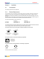
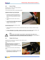
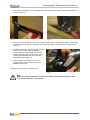
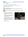
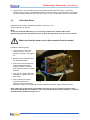
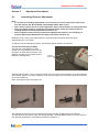
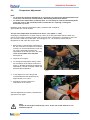
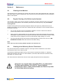
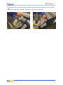
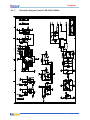
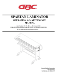
Technical Service Manual
11
Front Matter
TM
TM
ProSeal 25 / ProSeal 44
Technical Service Manual
REV 2.0
Revision History
Amendments will be listed on this page, including their descriptions and dates.
REV Date
1.0 Nov 1999
2.0 Feb 2000
i
Description
Original version (pre-release).
Released version; the manual covers US as well as EU machines.
Page numbering starts with each section.
Changed pages: all.
The pressure- and nip setting procedures have been changed in accordance with
the new roller setup (uncrowned top roll, crowned bottom roll).
i
February 2000
Front Matter
Safety Statements
TM
The ProSeal laminators have been designed with operator safety as a primary objective; however,
operators must be familiar with the controls, as well as the operation before using the unit.
The electrical and drive-system components are isolated from contact with the operator by enclosing
them within plastic end covers that are bolted on. Only qualified service technicians should remove
these protective covers after power to the machine is removed including disconnecting the power
cord.
The heated top roller can reach temperatures of 160C (320°F). For operator safety, a protective heatshield is mounted over the top roller, and attached to the top aluminum extrusion. Adequate ventilation
is guaranteed; because of this, the outside temperature of the extrusion will never exceed 45°C
(113°F).
Only qualified service technicians should remove the top extrusion in order to clean
the rollers if necessary.
Safety Features
The material inlet opening has a height that is in accordance with EN294 clause 4.5.2; the IEC1032
test finger cannot enter this opening.
The heating system is provided with an over-temperature device, which will shut off the top rollerheating element once a heating system failure occurs.
Caution
Everyone working around the laminator must avoid wearing loose fitting clothing
(ties!) or dangling jewelry, which could catch in the laminator rollers.
Technical Service hazards
Fire hazard – The laminator contains a heated roller which reaches temperatures of 160°C
(320° F). There is a danger of severe burns if the heated roller is touched during servicing.
Mechanical hazard – Failure to use caution near exposed rollers could result in physical
injury.
fig. 1
ii
ii
February 2000
Front Matter
Note:
When performing procedures that require the side covers to be opened, ensure that
the power cable is disconnected from the mains. Several parts, like the mains switch
(1) and the overtemperature switch (2), could cause electrical shock if the power is not
disconnected!
1
2
fig. 2
iii
fig. 3
iii
February 2000
Table of Contents
Section 1.
1-1.
1-2.
Section 2.
2-1.
2-2.
Section 3.
3-1.
3-2.
Section 4.
4-1.
4-2.
4-3.
4-4.
4-5.
4-6.
4-7.
Section 5.
5-1.
5-2.
5-3.
Section 6.
6-1.
6-2.
6-3.
Section 7.
7-1.
Section 8.
8-1.
8-2.
8-3.
iv
Machine Characteristics
Machine Description........................................................................................1-1
Machine Specifications ....................................................................................1-1
Installation
Preinstallation.................................................................................................2-1
2-1-1.
Electrical Requirements ................................................................2-1
2-1-2.
Workspace Requirements.............................................................2-2
Setup .............................................................................................................2-2
Theory of Operation
Control Knob...................................................................................................3-1
Control Panel..................................................................................................3-2
Disassembly / Reassembly Procedures
Opening / Closing the Aluminium Top Cover .....................................................4-1
Feed-in Table..................................................................................................4-2
Plastic Side Covers .........................................................................................4-2
Heating Element .............................................................................................4-4
Software.........................................................................................................4-6
Rear Panel .....................................................................................................4-7
Solid State Relay ...........................................................................................4-8
Adjustment Procedures
Laminating Pressure Adjustment ......................................................................5-1
Nip Adjustment ...............................................................................................5-2
Temperature Adjustment .................................................................................5-6
Maintenance
Cleaning of the Machine..................................................................................6-1
Regular Cleaning of the Rollers by the Operator................................................6-1
Cleaning of the Rollers by Service Technicians .................................................6-1
Troubleshooting
Troubleshooting..............................................................................................7-1
Diagrams
Electrical Schematics ......................................................................................8-1
8-1-1.
Schematic Installation Diagram ProSeal 25 – 110V/60Hz................8-1
8-1-2.
Schematic Installation Diagram ProSeal 44 – 110V/60Hz................8-2
8-1-3.
Schematic Diagram Control PCB 110V 50/60Hz.............................8-3
8-1-4.
Schematic Diagram Controlpanel ..................................................8-4
8-1-5.
Schematic Installation Diagram ProSeal 25 – 230V/50Hz................8-5
8-1-6.
Schematic Installation Diagram ProSeal 44 – 230V/50Hz................8-6
8-1-7.
Schematic Diagram Control PCB 230V 50/60Hz.............................8-7
Certified Electrical Components Lists & Spare Part Codes .................................8-8
8-2-1.
110VAC/60Hz Machines ...............................................................8-8
8-2-2.
230VAC/50Hz Machines ...............................................................8-9
Mechanical Spare Parts List, Assembly Drawings & Exploded Views................8-10
8-3-1.
Mechanical Spare Parts List........................................................8-10
8-3-2.
Assembly Drawings & Exploded Views ........................................8-11
iv
December 1999
Machine Characteristics
Section 1.
1-1.
Machine Characteristics
Machine Description
TM
TM
The ProSeal 25 and ProSeal 44 laminators are electro-mechanical devices containing two silicone
rollers, a heating element for the top roller, an electronic PIZ controller for a fixed temperature, and a
synchronous drive AC motor to maintain a constant process speed.
The ProSeal laminators have been designed to be used with ProSeal Pouch Boards and ProSeal
Flexible Pouches. When used with these products, one is able to mount, mount and laminate, and
encapsulate prints in one step.
Each machine is provided with a User Manual; the purpose of this manual is to outline the materials
and processes when using ProSeal supplies using this laminator, to create signs, displays, and
flexible graphics with professional results. The manual includes instructions of various laminating
procedures, which are meant to give the user comprehensive information needed for the efficient use
of his laminator.
TM
TM
TM
TM
These machines have not been tested with any other materials and are not recommended for use with
products other than ProSeal supplies.
TM
TM
The US versions of the ProSeal machines are provided with fixed powercables and NEMA plugs; the
European versions are provided with Euro appliance inlets (see also Section 8).
TM
The ProSeal laminators meet the Machinery Directive (89/392/EEC & applicable amendments). They
rd
are ETL and cETL listed per directive UL 1950 3 Edition 1995 and CAN/CSA C22.2 No. 950-95.
1-2.
Machine Specifications
TM
TM
ProSeal 25
ProSeal 44
Mechanical
Height
Overall Width
Depth
Net Weight
Shipping Weight
12” (305 mm)
40” (1016 mm)
15” (380 mm)
77 lbs. (35 kg)
90 lbs. (41 kg)
12” (305 mm)
58” (1473 mm)
15” (380 mm)
154 lbs. (70 kg)
172 lbs. (78 kg)
Electrical
US version
EU version
110VAC/60Hz 12A
230VAC/50Hz 7A
110VAC/60Hz 16A
230VAC/50Hz 9A
25” maximum (635 mm)
1 N/mm
1’/min (305 mm/min)
311-320°F (155-160°C)
0
(closed nip)
1/16” (1.5 mm)
1/8” (3 mm)
3/16” (5 mm)
¼”
(6 mm)
44” maximum (1120 mm)
0.8 N/mm
1’/min (305 mm/min)
311-320°F (155-160°C)
0
(closed nip)
1/16” (1.5 mm)
1/8” (3 mm)
3/16” (5 mm)
¼”
(6 mm)
60766
60794
60824
60853
Process
Working width
Roller Line Pressure
Process speed
Process temperature
Nip Settings
Order Codes
US version
EU version
1
1-1
February 2000
Installation
Section 2.
2-1.
Installation
Preinstallation
The following requirements are applicable:
2-1-1.
Electrical Requirements
This unit should only be connected to a power supply outlet of the voltage, amperage, and frequency
marked on the rear panel. The laminator has a grounded plug (three prongs). To reduce the risk of
electrical shock, this plug is intended to fit only a grounded outlet of the proper amperage, and in only
one way.
The US versions of the ProSeal machines are provided with fixed powercables and NEMA plugs; the
European versions are provided with Euro appliance inlets (see also Section 8).
TM
The electrical specifications of the machines are:
ProSeal 25
110VAC/60Hz 12A
230VAC/50Hz 7A
US version
EU version
ProSeal 44
110VAC/60Hz 16A
230VAC/50Hz 9A
The ProSeal machines must be installed next to the power outlet; extension cords are not to be
used. The plug and the outlet must be easily accessible by the operator.
For the US versions, there are two types of outlets (receptacles), shown below.
G
L
G
N
NEMA 5-15R
Using 15 Amp Breaker
ProSeal 25
L
N
NEMA 5-20R
Using 20 Amp Breaker
ProSeal 44
Note: T-slot is not applicable for
Canada
For both EU versions, in the UK, the following is applicable:
BS 1363 – 13A
wall receptacle:
Use the provided
BS 1363 plug
For both EU versions, mainland Europe, the following is applicable:
French
Belgium
German, Netherlands
Portugal, Spain
Use the provided Schuko plug (10A).
1
2-1
February 2000
Installation
Wirecolours:
General (EU)
Blue
Yellow/Green
Brown
2-1-2.
•
•
•
•
•
USA
White
Yellow/Green
Black
Name
Neutral
Ground
Phase (Live)
Workspace Requirements
This unit should be situated away from heat sources such as heat registers or stoves.
The laminator’s location or position should not interfere with its proper ventilation.
There should be enough space around the laminator to feed-in, exit, and trim mounted and/or
laminated images.
The background dust level must not exceed that found in a typical office/computer room
environment.
The work area should be level, flat, and well lit.
2-2.
Setup
Procedure:
1.
2.
3.
4.
5.
6.
7.
2
Open the box, and lift the machine out (at least two persons necessary!). Grasp the machine 8”10” (200mm-250mm) from either side, at the bottom aluminum extrusions. Be careful: the
polyethylene bag is slippery!
Place the machine on the work area described under 2-1-2.
Remove the protective polystyrene foam end covers.
Remove the polyethylene bag.
Remove the protective sheet, placed between the rollers. To do this: push the knob, situated at
the right-hand side, fully inward, and rotate fully clockwise.
Check for damages.
Plug the power cable into the grounded outlet as described under 2-1-1. The machine will now
start and heat up.
2-2
February 2000
Theory of Operation
Section 3.
3-1.
Theory of Operation
Control Knob
The Control Knob (see figure 4) is located on the right hand side of the laminator and is operated from
the front of the machine. The Control Knob has four (4) purposes:
1.
2.
3.
4.
Turn the power on.
Turn the heat on.
Turn the rollers on.
Adjust the height of the rollers.
The Control Knob can be operated by pushing it in
approximately 1/4” (6mm) to the left. Once the
knob has disengaged from the stop, it may be
rotated forward or backward (clockwise or counterclockwise, viewed from the right hand side of the
unit).
To switch the power on, push the knob in and
rotate it slowly towards you (counter clockwise as
viewed from the right side of the unit). The top LED
will light up to indicate that the power is on.
fig. 4
Continue to rotate the knob until the desired measurement corresponds with the indicator window at
the base of the knob. Inside the window, the rotation possibilities are shown. Select the measurement
that indicates the thickness of the material you will be using with the machine. Releasing the knob so
that it moves back to the right and clicks into place will set the rollers for use. The measurements on
the knob, ¼”, 3/16”, 1/8” and 1/16” (6, 5, 3, 1.5 mm) correspond to ‘Pouch board thickness’. There is
also a fully closed stop for future film only applications.
To turn the laminator off, grasp the control knob and push to the left, rotate the knob away from you
as far as it will go (clockwise). This will shut off the machine and open the rollers to permit objects to
be removed.
Internal functionality
See figure 5.
Inside the machine, a rod is mounted
between the left- and righthand framesheets.
The knob is mounted on the rod; it allows
axial movement, but no radial movement. The
knob is provided with a pin (1), that falls in the
indents (2) of a bracket (3). The same rod is
provided with an eccentric (4) on either side
of the machine. These eccentrics push or pull
the arms (5), where the top roller is mounted
in, upward or downward. The mains switch is
mounted in such a way, that it switches the
power off once the are is in its highest
position.
5
1
2
4
3
fig. 5
1
3-1
February 2000
Theory of Operation
3-2.
Control Panel
The Control Panel (see figure 6) is located on the front right of the machine and has three LED
indicators. A diagram of the Control Panel is shown in figure 7.
1.
The top LED when lit indicates the machine is
plugged in and the power is on.
2.
The middle LED indicates if the heat is on. Heat
is required for ProSeal Pouch Boards and
ProSeal Flexible Pouches. If lit, the laminator is
in Hot Operation Mode and will heat up to its
factory setting. If not lit, the laminator is in Cold
Operation Mode.
3.
The bottom LED is the Temperature Ready
Indicator. If flashing slowly this indicates the
laminator is heating up and has not yet reached
process temperature. A steady light indicates
the unit has reached process temperature and
fig. 6
is ready for use. A rapid blinking light indicates
that the machine is too hot. This occurs when changing from Hot Mode to Cold Mode. In this case,
a steady light indicates the machine has cooled sufficiently for cold processes.
Below the LED lights are two Push Buttons.
1.
The top button controls the heating of the roller; it switches the heater on or off. Pushing this
button toggles the machine from Hot to Cold or Cold to Hot Operation. The bottom LED light when
constantly on, will indicate the appropriate temperature as been reached.
2.
The lower button reverses the direction of the motor. The motor will continue to run in reverse until
the button is released. This is used to clear jams or foreign objects, should one be drawn into the
laminator.
ISO symbol, meaning:
- Power has been switched on
- All electronic functions are OK
LED (green)
Lit when machine is switched. on
LED (green)
Lit when heating system is
active.
IEC symbol, meaning:
Heating system
LED (green)
- Flashes at a slow rate if the roll temp
is too low
- Steady if the roll temp is OK and
machine is ready.
- Flashes at a fast rate if the roll temp is
too high
IEC symbol, meaning:
Temperature controller (status)
IEC symbol, meaning:
Top roller heater
Pushbutton function:
Switching the heating system
on/off, middle LED will indicate if
heaters are on (LED is on) or off
(LED is off.)
IEC symbol, meaning:
toggle function (on/off)
Pushbutton function:
Reversing the forward movement of the rollers
(momentary action: as long as this button is
pressed)
IEC symbol, meaning:
reverse (roller) movement
fig. 7
2
3-2
February 2000
Disassembly / Reassembly Procedures
Section 4.
4-1.
Disassembly / Reassembly Procedures
Opening / Closing the Aluminum Top Cover
Necessary tools: medium flat head screwdriver.
Approximate time: 1 minute.
To open the cover, do the following steps:
1.
Insert the screwdriver in one of the holes,
situated on the top of the cover. Make sure,
that the head fits in the screw, mounted
directly underneath this hole. See figure 8.
2.
Rotate the screwdriver approximately ¼
turn; the direction is not important, as the
screw is a so-called ‘quarter-turn snap-in
screw’.
3.
Repeat this at the other side of the top
cover.
4.
Open the top cover, until it rests on the
feed-in table.
fig. 8
To close and lock the cover, proceed with the following steps:
1.
Do not close the cover yet, but rotate both screws back ¼ turn (to their original position). This is
easier when the cover is still open.
2.
Now close the cover.
3.
Press, using the screwdriver, both screws until they snap back into their locks.
Note:
When performing the Temperature Adjustment Procedure, it is convenient to close the cover without
locking the screws. This is called the ‘unlocked position’.
Note:
Please make sure, that after any procedure, requiring the top cover to be opened,
the top cover is closed and locked. For safety reasons the operator is not allowed
to have free access to the hot roller and roller nip.
1
4-1
February 2000
Disassembly / Reassembly Procedures
4-2.
Feed-in Table
Necessary tools: medium flat head screwdriver.
Approximate time: 1 minute.
To remove the feed-in table, do the following steps:
Insert the screwdriver in one of the holes,
situated on the feed-in table. See figure 9.
1.
Rotate the screwdriver approximately ¼
turn; the direction is not important, as the
screw is a so-called ‘quarter-turn snap-in
screw’.
2.
Repeat this at the other side of the top
cover.
3.
Lift the table approximately 20 mm (3/8”) by
means of the two knurled knobs, and slide it
straight out of the machine.
fig. 9
To insert and lock the feed-in table, proceed
with the following steps:
1.
Insert the table back into the machine, and make sure that it goes in straight, otherwise it might
get stuck.
2.
Once the table falls into it’s position, rotate the screws back ¼ turn (to their original position). Use
the same screwdriver to press both screws until they snap back into their locks.
Note:
Please make sure, that after any procedure, requiring the feed-in table to be
removed, the feed-in table is closed and locked. For safety reasons the operator is
not allowed to have free access to the hot roller and roller nip.
4-3.
Plastic Side Covers
Necessary tools: hexalobular screwdriver TX25, Allen key 4mm.
Approximate time: 5 minutes.
Note:
To remove the covers, it is necessary to
perform the ‘Opening / Closing the
Aluminum Top Cover’ Procedure, described
in Section 4-1.
To remove the side covers, do the following
steps:
1.
Remove the two self-tapping screws, using
the TX25 driver, as shown in figure 10. The
right hand cover is shown here.
fig. 10
2
4-2
February 2000
Disassembly / Reassembly Procedures
2.
Remove the self-tapping screw, situated at the rear side of the machine, using the TX25 driver, as
shown in figure 11.
fig. 12
fig. 11
3.
Remove, using the Allen key 4mm, the two M5 socket screws, situated at the bottom of the cover.
It’s best practice to slide the machine to the edge of the table or counter where it’s placed. See
figure 12.
4.
Carefully remove the right hand cover from the
frame of the machine. Now, a flatcable,
connected to the Control PCB, will become
visible. Hold the cover with one hand, whilst
removing the flatcable connector from the
PCB. See arrow in figure 13.
5.
The procedure for the left-hand cover is
similar, though it’s obvious that there’s no
flatcable on this side.
Assembly of the cover is in reverse order.
fig. 13
Note:
Make sure, that the flatcable has been placed back onto the PCB connector. Take
care, that the flatcable is not twisted.
3
4-3
February 2000
Disassembly / Reassembly Procedures
4-4.
Heating Element
Necessary tools: Allen key 3mm.
Approximate time: 10 minutes.
Note:
To disassemble / reassemble the heating element, it is necessary to perform the ‘Plastic Side
Covers’ Procedure, described in Section 4-3.
Make sure that the power cord is disconnected from the mains!
The heating element (see figure 14), is a quartz
tube, having a spiral wound filament mounted
inside.
The quartz tube is fragile; take care when
handling the element.
To exchange the heating element, perform the
following procedure:
fig. 14
1.
Remove, on the left-hand side of the machine, the blue fast-on connector (1) from the
overtemperature switch (2). See figure 15.
2.
Slide the heater wire out of the slot that’s in the heater bracket.
2
1
fig. 15
3.
4
fig. 16
Cut, at the right hand side of the machine, the two tie-wraps, that hold the wire of the heating
element to the other two (black) wires. See figure 16.
4-4
February 2000
Disassembly / Reassembly Procedures
4.
Loosen the screw, which attaches the heater wire to the Solid State Relay. See figure 17.
fig. 17
5.
fig. 18
Remove the heater bracket on the right hand side of the machine (see figure 18), and slide the
heater wire out of the slot, that’s in the heater bracket.
Now, the heating element can be taken out of the roller.
Note:
When a heating element has to be installed into the roller, the quartz tube has to be cleaned first.
Proceed as follows:
Insert the heating element, with the end having the shortest wire, into the roller core. Make sure,
that the wire is bent straight, to smoothen the insertion.
Whilst inserting, clean the quartz tube with a lint-free cloth, lightly dampened with IPA (Isopropanol).
Do not touch the quartz tube with your fingers!
This is important, because fingerprints will burn when the heater is on, and can possibly damage the
quartz tube.
See figure 19.
Always be very careful
when using IPA! IPA is
very flammable!
The flash point of IPA is
11°C (51.8°F). The selfignition temperature is
400°C (752°F).
Once the element is placed in the roller,
reassemble all parts in the reverse order.
Note:
Do not forget to attach two new tie-wraps, and
mount them exactly as the two that were
removed previously.
5
4-5
fig. 19
February 2000
Disassembly / Reassembly Procedures
4-5.
Software
The Control System of the ProSeal Laminator is software driven.
The software resides in a small embedded controller, mounted on the Control PCB.
Necessary tools: small flat-head screwdriver.
Approximate time: 3 minutes.
Note:
To change / upgrade the software, it is necessary to perform the ‘Plastic Side Covers’
Procedure, described in Section 4-3.
Make sure that the power cord is disconnected from the mains!
1.
Insert the small screwdriver between the
processor and it’s socket, mounted on the
PCB. See figure 20. Carefully remove the
processor.
2.
To insert the new processor, make sure that
the small pins are not bent, and that their pinto-pin distance matches the hole-to-hole
distance on the socket.
3.
Carefully insert the new processor. Make sure
that the pins do not bend. Make sure as well,
that the small notch on the side of the
processor matches the symbol, printed on the
PCB. The notch must be on the left side (arrow
in figure 20).
4.
6
fig. 20
Discard the old processor.
4-6
February 2000
Disassembly / Reassembly Procedures
4-6.
Rear Panel
Necessary tools: Phillips crosshead screwdriver (medium), open-ended spanner 8mm, knife.
Necessary materials: two tie-wraps (2.5 – 3 mm wide).
Approximate time: 10 minutes.
Note:
To remove the rear panel, it is necessary to perform the ‘Plastic Side Covers’ Procedure (see
Section 4-3) first.
Perform the following steps:
1.
See figure 21.
Cut the two tie-wraps (arrows) at the left-hand side of the machine. Remove the blue cable
connector from the overtemperature switch (1). Remove the nut from the ground connection stud
(2).
1
2
fig. 21
fig. 22
2.
Remove the seven crosshead self-tapping screws from the rear panel (see figure 22).
3.
Carefully pull the rear panel backward, whilst pulling the two wires (the yellow/green and the blue
one) back through the plastic protective bushing, that’s mounted in the left-hand framesheet.
4.
When the wires are clear from the bushing, swing the rear panel a quarter turn away from the
machine. Take care not to damage the wires (1) going to the motor. See figure 23.
5.
To mount the rear panel back to the machine
again, swing it far enough towards the
machine, to insert the two wires into the
bushing.
1
6.
Whilst pulling the wires through the bushing,
swing the rear panel further to the machine.
7.
When mounting the rear panel, make sure that
the two slots (2), on either side in the panel,
grab the two bent parts at the underside of the
framesheets.
8.
Next, push the rear panel upward to its original
position and use the crosshead screws to
fasten the panel again. Do not forget the
serrated washers!
7
4-7
2
fig. 23
February 2000
Disassembly / Reassembly Procedures
9.
Apply the two new tie-wraps exactly on the original positions (into the holes), put the blue
connector back onto the overtemperature switch, and mount the ground wire back to it’s position.
Put the serrated washers back the way they came off: one on either side of the two wire-eyelets.
4-7.
Solid State Relay
Necessary tools: medium flat-head screwdriver, Allen key 3 mm.
Approximate time: 5 minutes.
Note:
To remove the Solid State Relay, it is necessary to perform the ‘Plastic Side Covers’
disassembly procedure (see Section 4-3) first. Only the right hand cover has to be removed.
Make sure that the power cord is disconnected from the mains!
Perform the following steps:
1.
Loosen all four screws that
clamp the wires. They are
marked 1 through 4. See figure
24.
2.
Bend the wires a bit away from
the Solid State Relay.
3.
Remove the two M4 bolts that
hold the Solid State Relay
together with the bent sheet
(fire enclosure), that’s mounted
behind it.
4.
Now you can remove the Solid
State Relay, together with the
bent sheet.
5.
When mounting the Relay,
fig. 24
make sure that the four
clamping screws and the two
M4 bolts are tight. Don’t forget the serrated washers that belong under the M4 bolt heads.
Note: make sure, that the relay is mounted in the proper way: the coding on the blue wires
should correspond with the numbers on the relay; the two black wires on clamp no. 1, the wire
from the heating element on clamp no. 2.
8
4-8
February 2000
Adjustment Procedures
Section 5.
5-1.
Adjustment Procedures
Laminating Pressure Adjustment
Note:
• To perform the following adjustments, it is necessary to remove both plastic side covers
first. See Section 4-3: Disassembly / Reassembly Plastic Side Covers.
• Note: the top roller must be at room temperature, before this procedure is being performed.
• Next, the heating element, including both heater brackets, has to be removed. See the
‘Heating Element’ Procedure described in Section 4-4.
• After completion of the Laminating Pressure Adjustment procedure, it is mandatory to
continue with the Nip Adjustment Procedure described in Section 5-2.
Necessary tools: 10mm open-ended spanner, small flat-head screwdriver, Allen key 2mm.
Approximate time: 15 minutes.
To adjust or set the laminating pressure, the following special devices are required:
The Pressure Display Unit (PDU).
This unit has to be plugged in a wall
socket; the two pressure sensors can be
plugged in at either side of the PDU. The
pressure (actually: force) display reads in
Kilograms. See figure 25.
pressure
sensors
PDU
fig. 25
Together with the PDU, a set of sensor-supports has to be used. Each machine type needs a different
set of sensor-supports. For the ProSeal 25, a set, shown in figure 26 is necessary; figure 27 shows the
set for the ProSeal 44.
Note: each figure shows only half the set.
fig. 26
support set for ProSeal 25
fig. 27
support set for ProSeal 44
The tools shown above have to be inserted in the roller journals, at either side of the machine.
To insert the tools into the top roller, the heating element, including both brackets, has to be removed
first. See the disassembly / reassembly procedure in Section 4-4.
1
5-1
February 2000
Adjustment Procedures
Next, the nip adjustment strips have to be loosened on either side of the machine. See figure 28 and
29; the detailed adjustment strip is shown figure 30. Note that the strip must not touch the top roller
bearing housing during the pressure adjustment procedure.
adjustment
strip
fig. 28
fig. 29
Note:
The figures shown above, show the adjustment
strips on the ProSeal 25; the adjustment strips on
the ProSeal 44 are positioned under the bearing
housing, they are larger, and mounted with two
bolts.
Make sure that there is some space between the
adjustment strips and the bearing housings, see
figure 30.
At the left-hand side of the machine, the
overtemperature switch has to be turned away, to
the right. In order to do this, remove the M4 socket
screw at the top of the switch, and loosen the other
M4 socket screw a bit, using the Allen key 3mm.
See figure 31, (2).
fig. 30
To place the pressure
sensors between the
supports, it is necessary
to open the roller nip fully.
In order to do this, push and
rotate the nip adjustment
knob, situated on the righthand side of the machine,
inward, and fully clockwise.
Insert the supports, together
with the sensor, all the way
into the roller journals. The
1
sensor supports should
have their flat sides facing
each other (see fig. 31, 1),
and the holes in the sensor
should fit over the pins in the
supports.
2
2
fig. 31
5-2
February 2000
Adjustment Procedures
To insert a sensor support
into the right-hand journal of
the bottom roller, the belt
tensioner assembly has to
be removed first (already
removed in figure 32). Use
the small screwdriver to
remove the retaining clip
from the tensioner arm pivot
axis.
See figure 32.
After disassembly of the belt
and tensioner, the supports
can be inserted (1) as
previously described.
1
2
fig. 32
Now, push and rotate the nip adjustment knob
until the pin, mounted in the knob, falls into the
first notch (relative to top) from the indent
bracket.
See figure 33.
Pressure will be applied to the pressure
sensors, and the pressure can be read on the
PDU.
To change the pressure, place the 10mm
open-ended spanner on the M6 nut, that’s
directly under the compression spring (so, the
upper jamnut).
On the left-hand side of the machine, it’s best
to remove the blue connector from the
overtemperature switch, to ease access with
the spanner. See figure 34.
Rotate clockwise to decrease the pressure,
counter-clockwise to increase the pressure
(seen from above).
fig. 33
The pressure settings for each PDU display
(so, for either side of the machine) should be
as follows:
ProSeal 25 – 35 kilograms.
ProSeal 44 – 46 kilograms.
If necessary, change these values as
described above.
After the adjustment, remove the pressure
sensors and the supports.
fig. 34
Assemble all parts in reverse order.
Now, it is mandatory to continue with the Nip Adjustment Procedure described in Section 5-2.
3
5-3
February 2000
Adjustment Procedures
5-2.
Nip Adjustment
Note: to perform the following adjustments, it is necessary to remove both plastic side covers first.
See Section 4-3: Disassembly / Reassembly Plastic Side Covers.
Necessary tools: Allen key 4mm.
In addition, a metal adjustment sheet, having a specific thickness, is necessary.
For the ProSeal 25, the thickness of this sheet must be 0.5 mm; size: 700x250 mm.
For the ProSeal 44, the thickness of this sheet must be 1.25 mm; size: 1150x250 mm.
Approximate time: 5 minutes.
Note: the top roller must be at room temperature, before this procedure is being performed.
1.
Set the roller nip opening to its maximum position by pushing and turning the nip setting knob fully
clockwise .
2.
Next, the nip adjustment strips have to be loosened on either side of the machine (if not loosened
already in case the previous procedure has been performed). See figure 35 and 36; the detailed
adjustment strip is shown figure 37. Note that the strip must not touch the top roller bearing
housing.
adjustment
strip
fig. 35
fig. 36
Note:
The figures above show the adjustment strips on the
ProSeal 25; the adjustment strips on the ProSeal 44
are positioned under the bearing housing, they are
larger, and mounted with two bolts.
3.
Make sure that there is some space between the
adjustment strips and the bearing housings, see
figure 37.
4.
Place the adjustment sheet between the rollers.
Make sure that the sheet covers the bottom
roller completely.
4
5-4
fig. 37
February 2000
Adjustment Procedures
5.
Push and rotate the nip setting knob fully
counter-clockwise , until the pin, mounted
in the knob, reaches its lowest position in
the indent bracket. See figure 38.
The top roller is now applying pressure on the
adjustment sheet.
lowest
position
fig. 38
6.
Push the adjustment strip against the top
roller bearing housing. Whilst holding the
strip in this position, fasten the M5 bolt(s)
firmly using the Allen key 4mm. See figure
39.
7.
Perform the previous step at either side of
the machine.
push
8.
Open the roller nip again, to remove the
adjustment sheet.
fig. 39
5
5-5
February 2000
Adjustment Procedures
5-3.
Temperature Adjustment
Note:
• To perform the following adjustments, it is necessary to remove the right-hand plastic side
cover first; see Section 4-3: Disassembly / Reassembly Plastic Side Covers.
• To measure the temperature of the top roller, it is necessary to have the interlocking bolts
of the top cover in the unlocked position; see Section 4-1: Opening / Closing the
Aluminium Top Cover.
Necessary tools: Infrared Temperature meter, small flat head screwdriver.
Approximate time: 30-60 minutes.
The top roller temperature should be set to 160°C, ± 4°C (320°F, ± 7.5°F).
Changing the temperature to a higher value (in case it is too low) goes faster than the other way
around, as the roller is heating up faster than it will cool down. Therefore it is necessary to open the
top cover if the roller has to cool down, and wait approx. 15 - 20 minutes to assure that the
temperature is well under the correct value.
1.
Before taking a temperature measurement,
the top cover has to be closed for at least 5
minutes. To do the measurement: open the
top cover, and quickly measure the
temperature of the top side of the top roller;
close to the middle of the machine.
See figure 40.
2.
Close the cover again.
3.
To change the temperature setting, insert
the screwdriver in the trimpot as shown in
figure 41. Rotating clockwise increases the
temperature, counter clockwise rotation will
decrease the temperature.
fig. 40
4.
A five-degree turn of the trimpot will
increase/decrease the temperature by
approximately 10°C (18°F).
5.
Repeat the previous steps if the
temperature is not correct.
After this adjustment procedure, assemble the
right-hand cover again.
fig. 41
Note:
Please do not forget to lock the top cover, as the user of the machine is not
allowed to open it.
6
5-6
February 2000
Maintenance
Section 6.
6-1.
Maintenance
Cleaning of the Machine
The laminator may be cleaned by the operator with a lint-free cloth, lightly dampened with a mild soap
and water solution. Spray-on cleaners are not to be used. No part of the machine is to be immersed in
water or other liquids.
6-2.
Regular Cleaning of the Rollers by the Operator
The laminating rollers of the machine should be periodically cleaned of adhesive build up that might
occur during normal operation. This should be performed a few times per day, using the ProSeal
Cleaning Board.
ProSeal Cleaning Boards are specially designed to attract and capture any adhesive that may be
clinging to the rollers. They are made from materials that will not damage or cause excessive wear to
the ProSeal Laminator.
1.
Turn on the unit and set for Hot Temperature Operation. Once the machine has reached
process temperature set the Control Knob to 3/16”.
2.
Slowly insert the Cleaning Board into the inlet opening. Ensure that the board enters centered
and straight. A gentle push may be required to start the board into the machine. Hold the edges
of the board until it is engaged in the unit and the laminator begins pulling it on its own.
3.
The board will feed through the laminator and automatically exit at the rear of the unit. THE
BOARD WILL BE HOT! Allow the board to lie flat while cooling.
Note:
This is the only roller cleaning method operators are allowed to do.
6-3.
Cleaning of the Rollers by Service Technicians
Only service technicians are allowed to perform a thorough surface maintenance of the rollers.
This should be done once or twice per year.
To perform this cleaning procedure, the top cover has to be opened. See Section 4-1 ‘Opening /
Closing the Aluminum Top Cover. On the ProSeal 44, the feed-in table should be removed as well,
see Section 4-2 ‘Feed-In Table’.
The rollers should be cleaned with a lint-free cloth, lightly dampened with IPA (Isopropanol).
Always be very careful when using IPA! IPA is very flammable!
The flash point of IPA is 11°C (51.8°F). The self-ignition
temperature is 400°C (752°F). Please make sure that the top roller
is cooled down before cleaning.
1
6-1
February 2000
Maintenance
It’s best practice to clean the top roller first; adhesive from the top roller is likely to fall on the bottom
roller.
See figure 42: cleaning the top roller, and figure 43: cleaning the bottom roller.
fig. 43
fig. 42
2
6-2
February 2000
Troubleshooting
Section 7.
7-1.
Troubleshooting
Troubleshooting
Problem:
The power LED does not come on, when the nip setting knob has been set to one of the nip settings
(board thicknesses).
Causes:
The power cable has not been plugged in the mains wall outlet.
Solution:
Plug the power cable into the mains outlet.
The processor, containing the software, is not installed.
Solution:
Install the software (see Software Installation, Section 4-5).
The processor, containing the software, is installed the wrong way around.
Solution:
Install the software properly (see Software Installation, Section 4-5).
The (external) mains circuit breaker is tripped.
Solution:
Reset the mains circuit breaker.
The flatcable, coming from the control panel in the right hand side cover, and the PCB, is not
connected.
Solution:
Perform the Cover Disassembly / Reassembly procedure (See Section 4-3).
The mains (micro) switch is defective.
Solution:
Replace the switch. See Section 8-3-2, Assembly Drawings & Exploded
Views, drawing no. 144-180 / 144-182, art. code 961-0007.
Problem:
The heating system LED (middle LED) does not come on, when the nip setting knob has been set to
one of the nip settings (board thicknesses), coming from the ‘off’ position.
Cause:
There is a fault in the controlpanel (if a ‘loose’ control panel works fine).
Solution:
Replace the right hand cover, containing the control panel. Perform the
Cover Disassembly / Reassembly procedure (See Section 4-3).
Problem:
The heating system LED (middle LED) is flashing at a fast rate, instead of being constantly lit.
Cause:
The temperature sensor wires are not connected properly.
Solution:
Check the wires of the sensor.
Problem:
The heating system LED (middle LED) is flashing at a slow rate, instead of being constantly lit.
Cause:
The temperature sensor wires are short-circuited.
Solution:
Check the wires, and replace the sensor if necessary. See Section 8-3-2,
Assembly Drawings & Exploded Views, drawing no. 144-184 / 144-186, art.
code 144-137 / 144-143.
Problem:
The temperature-ready LED keeps on flashing at a slow rate (after 20 minutes), once the heating has
been activated.
Causes:
The heating element is defective, or one of its connectors had not been installed.
Solution:
Check by performing the Heating Element assembly / reassembly procedure
(see Section 4-4).
1
7-1
February 2000
Troubleshooting
The Solid State Relay is defective (it has a permanent ‘open’ state; in this case, the red LED on
the Solid State Relay is constantly on).
Solution:
Replace the Solid State Relay, see Section 4-1.
The overtemperature switch is defective (it has a permanent ‘open’ state; in this case, the line
voltage can be measured between it’s connectors).
Solution:
Replace the overtemperature switch. See Section 8-3-2, Assembly Drawings
& Exploded Views, drawing no. 144-185 / 144-187, art. code 961-6003.
The Control PCB is defective (if the previous checks are OK).
Solution:
Replace the Control PCB.
Problem:
The temperature-ready LED starts flashing at a fast rate after some 20 minutes, and continues to do
so. The top cover is warmer than usual.
Cause:
The Solid State Relay is defective.
Solution:
Replace the Solid State Relay, see Section 4-1.
Problem:
Pouchboards are not drawn in by the machine, and the motor is making a louder humming noise (it’s
stalling). Only after pushing very hard, the boards are accepted.
Causes:
The Pouchboard is too thick for the chosen nipsetting.
Solution:
Check the nipsetting that corresponds to the boards used.
Boards of another make are used.
Solution:
Use only ProSeal Pouchboards.
The nip adjustment is not correct.
Solution:
Perform the Nip Adjustment procedure (see Section 3-2).
Problem:
The quality of the lamination is poor: silvery areas on dark surfaces are visible, or the edges of the
image are not sealed well.
Causes:
The roller temperature is too low.
Solution:
Perform the Temperature Adjustment procedure (see Section 3-3).
The roller pressure is too low.
Solution:
Perform the Laminating Pressure Adjustment procedure (see Section 3-1).
Problem:
The quality of the lamination is poor: especially laminated inkjet prints show bubbles.
Cause:
The roller temperature is too high.
Solution:
Perform the Temperature Adjustment procedure (see Section 3-3).
2
7-2
February 2000
Diagrams
Section 8.
Diagrams
8-1.
Electrical Schematics
8-1-1.
Schematic Installation Diagram ProSeal 25 - 110V/60Hz
1
8-1
February 2000
Diagrams
8-1-2.
2
Schematic Installation Diagram ProSeal 44 – 110V/60Hz
8-2
February 2000
Diagrams
8-1-3.
3
Schematic Diagram Control PCB 110V 50/60Hz
8-3
February 2000
Diagrams
8-1-4.
4
Schematic Diagram Controlpanel
8-4
February 2000
Diagrams
8-1-5.
5
Schematic Installation Diagram ProSeal 25 - 230V/50Hz
8-5
February 2000
Diagrams
8-1-6.
6
Schematic Installation Diagram ProSeal 44 - 230V/50Hz
8-6
February 2000
Diagrams
8-1-7.
7
Schematic Diagram Control PCB 230V 50/60Hz
8-7
February 2000
Diagrams
8-2.
Certified Electrical Components Lists & Sparepart Codes
8-2-1.
110VAC/60Hz Machines
See also Section 8-1-1 through 8-1-4.
DWG Name
REF
Manufacturer
SSR1 Solid State Relay Omron
Type
Technical
Details
UL
Listing no.
Sparepart
no.
G3NA-220B
240Vac / 20A
E64562
SP 961-0001
E1
heating element
Proseal 25
Quartz Tubing Inc.
144-158
120 Vac /1500W
N.A.
SP 144-158
E1
heating element
Proseal 44
Quartz Tubing Inc.
144-157
120Vac /1850W
N.A.
SP 144-157
S1
on/off switch
(microswitch)
Omron / Hartmann
V161C5 / MAB6
AC250V /15A
AC250V /16A
E32667 /
CSA LA
107892-2
SP 961-0007
S2
overtemp switch
Elmwood
2511L135-2040
AC 250V/ 25A
MH8267
SP 961-6003
M1
motor
SAIA-Burgess
UFR1UH
8F33CRN2A
110VAC / 60Hz / 4W
E63316
SP 964-0009
P1
print control pcb
115v ac
Hunt Graphics
963-0021
see underneath
N.A.
SP 963-0021
J2,J3
connector for P1 5
Hitaltech
way
HT255005
Imax=17A5
E167473
N.A.
T1
transformer
Era
BV 030-7293.0S 115V-9V-2VA
E113449
N.A.
K1
C6
C7
C8
relais
Capacitor
Capacitor
Capacitor
terminal block
mainplug / cable
Proseal 25
Omron
Philips
Philips
Philips
Farnell
G2R1 5Vdc
33620334
33620105
33620683
890-390
250V ac 10A
275V ac(X2)
275V ac(X2)
275V ac(X2)
32 A
N.A.
N.A.
N.A.
N.A.
N.A.
Any make
Nema 5 -15P
SJT 3x14AWG
E41643
E112471
E112471
E112471
E76048
E41542
LL14903
mainplug / cable
Proseal 44
Any make
Nema 5 -20P
SJT 3x12AWG
E41542
LL14903
SP 144-208
tri rated
internal wiring
(black)
Multicomp
AWG14
AWG18
AWG22
AWG14
AWG18
AWG22
UL1015
N.A.
tri rated
internal wiring
(blue)
Multicomp
AWG14
AWG18
AWG22
AWG14
AWG18
AWG22
UL1015
N.A.
tri rated
internal wiring
(green/yellow
Multicomp
AWG14
AWG18
AWG22
AWG14
AWG18
AWG22
UL1015
N.A.
Sleeving
Hellermann Tyton
277-873
10.0 mm
VW-1/Type 3
N.A.
Class 105T
snap bushing
Heyman
2066
11.1 mm
UL94V-2
SP 961-0005
nut cable gland
Hugro
587.13.01
polyamid
V-0
SP 961-0012
coupling nut
Hugro
184.1312.01
polyamid
V-0
SP 961-0011
plastic ties
Insolok
SP 144-211
T18-T30
nylon 66
E23190
N.A.
TS1
temperatue
Precision Engineering
sensor
Proseal
Ltd.
25
N.A.
N.A.
N.A.
SP 144-143
TS1
temperatue
Precision Engineering
sensor
Proseal
Ltd.
44
N.A.
N.A.
N.A.
SP 144-137
P2
controlpanel
N.A.
N.A.
N.A.
SP 144-073
8
De Naamplaat BV
8-8
November 1999
Diagrams
8-2-2.
230VAC/50Hz Machines
See also Section 8-1-4 through 8-1-7.
DWG Name
REF
Manufacturer
SSR1 Solid State Relay Omron
Type
Technical
Details
UL
Listing no.
Sparepart
no.
G3NA-220B
240Vac / 20A
E64562
SP 961-0001
E1
heating element
Proseal 25
Quartz Tubing Inc.
144-160
230 Vac /1500W
N.A.
SP 144-160
E1
heating element
Proseal 44
Quartz Tubing Inc.
144-159
230Vac /1850W
N.A.
SP 144-159
S1
on/off switch
(microswitch)
Omron / Hartmann
V161C5 / MAB6
AC250V /15A
AC250V /16A
E32667 /
CSA LA
107892-2
SP 961-0007
S2
overtemp switch
Elmwood
2511L135-2040
AC 250V/ 25A
MH8267
SP 961-6003
M1
motor
SAIA-Burgess
UFR1ND
5F25CRN2A
230VAC / 50Hz / 4W
N.A.
SP 964-0008
P1
print control PCB
Hunt Graphics
230VAC
963-0020
see underneath
N.A.
SP 963-0020
J2,J3
connector for P1
5 way
Hitaltech
HT255005
Imax=17A5
E167473
N.A.
T1
transformer
Era
BV 030-7305.0S
230V-9V-2VA
E113449
N.A.
K1
C6
C7
C8
relais
Capacitor
Capacitor
Capacitor
terminal block
Omron
Philips
Philips
Philips
Farnell
G2R1 5VDC
33620104
33620105
33620103
890-390
250V AC 10A
275V AC(X2)
275V AC(X2)
275V ac(X2)
32 A
E41643
E112471
E112471
E112471
E76048
N.A.
N.A.
N.A.
N.A.
N.A.
appliance inlet
Schurter
6100.43XX
10A / 250VAC
N.A.
SP 961-0003
RS Components
462-418
250VAC 10A
N.A.
SP 961-0017
Feller
VII-H05RRF3
G1.00-C13
250VAC 10A
N.A.
SP 961-0016
tri rated
internal wiring
(black)
Multicomp
AWG14
AWG18
AWG22
AWG14
AWG18
AWG22
UL1015
N.A.
tri rated
internal wiring
(blue)
Multicomp
AWG14
AWG18
AWG22
AWG14
AWG18
AWG22
UL1015
N.A.
tri rated
internal wiring
(green/yellow
Multicomp
AWG14
AWG18
AWG22
AWG14
AWG18
AWG22
UL1015
N.A.
Sleeving
Hellermann Tyton
277-873
10.0 mm
VW-1/Type 3
N.A.
Class 105T
snap bushing
Heyman
2066
11.1 mm
UL94V-2
SP 961-0005
plastic ties
Insolok
power cable UK
BS1363A
power cable EU
CEE 7-VII
T18-T30
nylon 66
E23190
N.A.
TS1
temperatue
Precision Engineering
sensor
Proseal
Ltd.
25
TH4075
N.A.
N.A.
SP 144-143
TS1
temperatue
Precision Engineering
sensor
Proseal
Ltd.
44
TH4074
N.A.
N.A.
SP 144-137
P2
controlpanel
N.A.
N.A.
N.A.
SP 144-073
9
De Naamplaat BV
8-9
November 1999
Diagrams
10
8-10
November 1999
Diagrams
8-3.
Mechanical Spare Parts List, Assembly Drawings & Exploded Views
8-3-1.
Mechanical Spare Parts List
11
Item
Sparepart code dwg added
assy top roller ProSeal 44"
assy bottom roller ProSeal 44"
assy top pull roller ProSeal 44"
assy nipknob ProSeal 44"
assy top roller ProSeal 25"
assy bottom roller ProSeal 25"
assy bottom pull roller ProSeal 44"
assy top pull roller ProSeal 25"
assy bottom pull roller ProSeal 25"
assy control PCB 230V, 50/60Hz
assy sensor TH4074 (ProSeal 44")
sticker knob
assy sensor TH4075 (ProSeal 25")
assy lh cover ProSeal
assy control PCB 115V, 50/60Hz
heater ProSeal 44"-US 115V / 1850W
heater ProSeal 25"-US 115V / 1500W
heater ProSeal 44"-EU 230V / 1850W
heater ProSeal 25"-EU 230V / 1500W
assy top cover ProSeal 44
assy top cover ProSeal 25
assy belt tensioner ProSeal 44"
sticker 'ProSeal 44'
sticker 'ProSeal 25'
assy rh frame ProSeal 44" - US
assy lh frame ProSeal 44" - US / EU
assy rh frame ProSeal 25" - US
assy lh frame ProSeal 25" - US / EU
assy rh arm (compl.) ProSeal 44"
assy lh arm (compl.) ProSeal 44"
assy rh arm (compl.) ProSeal 25"
assy lh arm (compl.) ProSeal 25"
assy top pouch guide PrSl 44"
assy top pouch guide PrSl 25"
assy rh arm pull roller (compl.)
assy lh arm pull roller (compl.)
assy rh cover (compl.) ProSeal
assy nipknob ProSeal 25"
assy lh interlock top cover
assy rh frame ProSeal 44" - EU
assy lh frame ProSeal 25" - EU
assy rh interlock top cover
assy rear sheet ProSeal 44" -US
assy US Power Cable 20A
assy rear sheet ProSeal 25" - US
assy US Power Cable 15A
assy feed-in table ProSeal 25'
assy feed-in table ProSeal 44"
assy rear sheet ProSeal 44" - EU
assy rear sheet ProSeal 25" - EU
assy belt tensioner ProSeal 25" - EU
drive belt ProSeal 44
drive belt ProSeal 25
machine foot
SP
SP
SP
SP
SP
SP
SP
SP
SP
SP
SP
SP
SP
SP
SP
SP
SP
SP
SP
SP
SP
SP
SP
SP
SP
SP
SP
SP
SP
SP
SP
SP
SP
SP
SP
SP
SP
SP
SP
SP
SP
SP
SP
SP
SP
SP
SP
SP
SP
SP
SP
SP
SP
SP
8-11
144-003
144-004
144-009
144-021
144-026
144-027
144-046
144-055
144-070
144-074
144-137
144-138
144-143
144-149
144-152
144-157
144-158
144-159
144-160
144-164
144-165
144-168
144-171
144-172
144-180
144-181
144-182
144-183
144-184
144-185
144-186
144-187
144-188
144-189
144-190
144-191
144-194
144-195
144-198
144-201
144-202
144-204
144-206
144-208
144-210
144-211
144-230
144-231
144-234
144-235
144-237
956-0002
956-0003
957-0000
Y
Y
Y
Y
Y
Y
Y
Y
Y
N
Y
N
Y
Y
N
N
N
N
N
Y
Y
Y
N
N
Y
Y
Y
Y
Y
Y
Y
Y
Y
Y
Y
Y
Y
Y
Y
Y
Y
Y
Y
Y
Y
Y
Y
Y
Y
Y
Y
N
N
N
November 1999
Diagrams
12
8-12
November 1999
Diagrams
8-3-2.
Assembly Drawings & Exploded Views
The next pages contain assembly drawings and exploded views.
13
8-13
November 1999