1
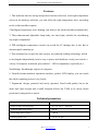
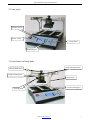
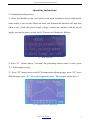
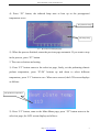
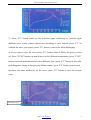
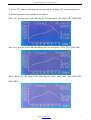
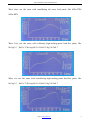
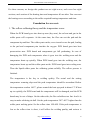
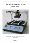
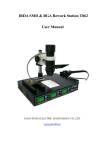
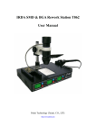
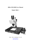
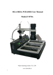
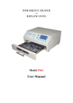
BGA IRDA WELDER T-890 USER MANUAL
BGA IRDA-WELDER USER MANUAL
MODEL: T-890
TAIAN PUHUI ELECTRIC TECHNOLOGY CO., LTD
http://www.tech168.cn
IRDA-WELDER T-890 USER MANUAL
Features:
1. This machine has the strong and perfect function selection, with eight temperature
waves in the memory software, you can select the right temperature wave according
to the solder/unsolder request.
2.Intelligent temperature wave heating, can achieve the solder/unsolder automatically.
3. Three-dimensional adjustable lamp body, use laser light, suitable for unsoldering
any-angle components.
4. PID intelligent temperature control can avoid the IC damage due to the fast or
uninterrupted warming up.
5. This machine has a super hot melt system, use infrared welding technology which
is developed independently, heat is easy to pierce and distribute evenly, can suit for a
variety of computer, notebook, play station’s BGA components, especially in a
Northbridge/ Southbridge chipset of computer.
6. Friendly human-machine operation interface, perfect LCD display, you can watch
the whole repairing process very clearly.
7. Ergonomic design, practical and easily operated. Good build quality but at the
same time light weight and a small footprint allows the T-890 to be easily bench
positioned, transported or stored.
Technical parameters
Complete machine power
1500W
Rated voltage and frequency
AC 110-230 V 60/50Hz
Infrared lamp body power
300 W
Preheating chassis power
1200 W
Working bench size
320 X 330 mm
Http://www.tech168.cn
1
IRDA-WELDER T-890 USER MANUAL
Infrared lamp body heating size
60 X 60 mm
Preheating chassis preheating size
245 X 260 mm
Preheating chassis temperature range
0 ℃-350 ℃
Size
316mm X 410mm X 290mm
Net weight
9.3 kg
Main parts
Welding table main body
1
Infrared lamp body
1
Portal frame
2
Power line
1
User manual(Compact disc)
1
Description of the main parts
1. Welding table main body
Lamp body
Circuit board support
Portal frame
Preheating chassis
Focusing knob
Slide support
Front panel
Http://www.tech168.cn
2
IRDA-WELDER T-890 USER MANUAL
2. Front panel
Display screen
Power switch
Press button
Indicator light
3. Portal frame and lamp body
Lamp body adjust knob
Moving hand wheel
Lamp connecting line
Portal frame
Circuit board support
Focusing knob
Http://www.tech168.cn
3
IRDA-WELDER T-890 USER MANUAL
Operating instructions:
1. Examination and operation,
1). Place this machine on an even surface with good ventilation and no combustible
items nearby. Leave at least 20mm on either side because the machine will emit heat
when in use. Check the power supply voltage, connect the machine with the power
supply, turn on the power switch, the LCD screen will display as follows:
5-1:Main manu page
2) Press “F1” button (about 2 seconds) the preheating chassis starts to work, press
“F1” button again to stop.
3). Press “F3” button enters to the PCB temperature adjusting page, press “F2” select
different page, press “F3” select the temperature wave. The example shows wave 3.
5-2:Temperature wave selecting page
Http://www.tech168.cn
4
IRDA-WELDER T-890 USER MANUAL
4). Press “F2” button, the infrared lamp start to heat up as the presupposed
temperature wave.
The preheater temp
The lamp temp
5-3:the LCD screen display page
5). When the process finished, return the previous page automatic. If you want to stop
in the process, press “F3” button.
2. The wave selection and setting
1). Press “F2” button enters to the select/set page, firstly, set the preheating chassis
preheat temperature, press “F3/F4” buttons up and down to select different
temperature, press “F1” button to save. When save succeed, the LCD screen displays
as follows:
The preheater temperature
2). Press “F5” button, come to the Main Manu page, press “F2” button enters to the
select/set page, the LCD screen displays as follows:
Http://www.tech168.cn
5
IRDA-WELDER T-890 USER MANUAL
3). Press “F2” button enters to the select/set page, following we provide eight
different wave cycles, please choose one according to your request, press “F1” to
confirm the wave you choose, press “F2” button, come to the Main Manu page
4). If you want to reset the wave, press “F5” button, when it flicker the grid, you can
set. Press “F3/F4” buttons up and down to select different temperature, press “F1/F2”
buttons forward and backward to select different time, press “F5” button to save.(the
grid disappear, change to the previous flicker status), press “F4” button come to next
Segment, the same method to set the wave, press “F1” button to save the current
wave.
The flicker grid
Http://www.tech168.cn
6
IRDA-WELDER T-890 USER MANUAL
5). Press “F2” button, the lamp starts heating up according to the setting temperature.
6) Each temperature wave purposes as follows:
Wave one; use the same with soldering the less lead paste, like 85Sn/15Pb 70Sn/30Pb
Wave two; use the same with unsoldering the less lead paste, 85Sn/15Pb 70Sn/30Pb
Wave three; use the same with soldering the more lead paste, like 63Sn/37Pb
60Sn/40Pb.
Http://www.tech168.cn
7
IRDA-WELDER T-890 USER MANUAL
Wave four; use the same with unsoldering the more lead paste, like 63Sn/37Pb
60Sn/40Pb.
Wave five; use the same with soldering high-melting-point lead-free paste, like
Sn/Ag3.5;Sn/Cu.75 Sn/Ag4.0/Cu.5 Sn95.5/Ag3.8/Cu0.7
Wave six; use the same with unsoldering high-melting-point lead-free paste, like
Sn/Ag3.5;Sn/Cu.75 Sn/Ag4.0/Cu.5 Sn95.5/Ag3.8/Cu0.7
Http://www.tech168.cn
8
IRDA-WELDER T-890 USER MANUAL
Wave seven; use the same with soldering lead-free solder in melting point, like
Sn/Ag2.5/Cu.8/Sb.5;Sn/Bi3.0/Ag3.0
Wave eight; use the same with unsoldering lead-free solder in melting point, like
Sn/Ag2.5/Cu.8/Sb.5;Sn/Bi3.0/Ag3.0
Attentions:
1. According to the chips size and welding technological requirements, select the
right wave to unsolder the chips, use tweezer or vacuum nozzle to remove the chips.
2. Infrared lamp temperature wave set, temperature and the rate of time can not be
greater than 2 ℃ / S, each time setting value cannot exceed 250 seconds.
3. If you want to reset to Factory Default, press “F1” and “F5” at the same time, then
turn on the power switch, when heard continuous buzzer is ok.
4. There are a lot kinds of solder paste, every company chooses is also not identical.
Http://www.tech168.cn
9
IRDA-WELDER T-890 USER MANUAL
For these reasons, we design this product can set eight waves, each wave has eight
sections, each section of the heating time and temperature all can alter. You can reset
the heating waves according to the solder required heating temperature and time.
Foundation for wave set:
1. The reflow soldering theory and the temperature wave:
When the PCB board goes into heat up area (dry area), the solvent and gas in the
solder paste will evaporate. At the same time, the flux can wet the pad and the
component tip and foot. The solder paste melts, caves in and covers the pad, leading
to the pad and component pins insulate the oxygen. PCB board goes into heat
preservation area. PCB board and components get full preheating. In case of
damaging the PCB and components when it goes into the welding area and the
temperature heats up quickly. When PCB board goes into the welding area, the
temperature heats up and the solder paste melts. PCB board goes into cooling area.
Then the liquid solder paste the soldering points solidify. The reflow process is
finished.
The temperature is the key to welding quality. The actual and the setting
temperature warming slope and the peak temperature should be accordant. Before
the temperature reaches 160℃, please control the heat up speed in about 1℃.If heat
up too quickly, the PCB board and the components will be damaged, and the PCB
board may be out of shape. On the other side, the flux volatilizes too fast. And it is
easy to make soldering tin ball. Set the peak temperature 20℃-40℃ higher than the
solder paste melting point. Set the reflow time 10S-60S. If the peak temperature is
low or the reflow time is short, it will affect the welding quality, and serious is
Http://www.tech168.cn
10
IRDA-WELDER T-890 USER MANUAL
causing the solder paste does not melt. If the peak temperature is high or the reflow
time is long, the metal power will be oxidized and affect the welding quality and
serious is causing the component and PCB board damaged.
2. The set of temperature wave:
Set the wave according to the solder paste and the above foundation. Different
solder paste, choose and set different waves. In addition, the temperature wave has
related to the PCB, the density and size of components. Generally lead-free welding
temperature should be higher 40℃ than melting point.
Instructions:
1. Examination and starting
Inspect the infrared lamp body, temperature sensor and power line to check if they are
in good connection.
2. Adjustment and preparatory work before sealing-off/repair
1). Put and adjust the PCB board:
Pull-out the slid support, unscrew the closing handle on the bracket, adjust the PCB
board bracket, and put the PCB board aim at the bracket rabbet. Put the PCB board
on the socket, screw the closing handle on the PCB board bracket, fix well the PCB
board; move the slid support to choose the suitable operating position.
2). Adjust the infrared lamp holder:
Unscrew the lamp body closing handle, move the lamp handle, and make the infrared
lamp laser aims at the middle of the sealing-off /repairing chip, screw the lamp body
closing handle. Adjust the lamp body height by adjust whirl the focusing knob. And
keep the ideal distance between the lamp holder and chip is 20-30mm.
Http://www.tech168.cn
11
IRDA-WELDER T-890 USER MANUAL
3). Adjust the infrared lamp temperature sensor:
Put the infrared lamp temperature sensor on or around the chip. Then adjust the
place of PCB board preheat temperature sensor, letting the sensor contacts the
preheat plate well. In order to let the temperature measurement exact, put some flux
around the chip and the head of sensor. At the same time, the BGA pad will be in
good condition. Can effectively prevent the pad be adhered and prevent the pad has
tin burr.
3. Sealing off/repair process:
The general sealing off process: fasten the PCB board, adjust it and the place of lamp,
make the infrared lamp laser aim at the chip and adjust the height of the lamp, place
the infrared lamp temperature sensor, put some flux, set the temperature of preheat
plate. Then choose the temperature wave of the lamp, turn on the preheat plate and
infrared lamp to heat up. When reach the peak temperature or the chip pad melts, put
away the chip by the tweezer or vacuum nozzle. After carry out the infrared lamp
temperature wave, it comes back automatically. When the main body cools down well,
you should turn off the power supply.
The general reflow process operation: the operation is about the same to the sealing
off. The differences are as the follow: first clean the pad and plant the solder ball,
preheat up the PCB board, place the chip directly, preheat up according the solder
ball reflow temperature, reflow and weld and cool down.
Sealing off/repair various kinds of the components, like CPU and GAP socket.
The operation is as follow: first use the aluminized paper to mantle the PCB fear heat
part and the other components. Then fix well the PCB board on the PCB board
Http://www.tech168.cn
12
IRDA-WELDER T-890 USER MANUAL
support. Then set the PCB preheat temperature between 160 and 180℃ and put the
temperature sensor near the sealing off component. Turn on the preheat plate for 3-5
minutes or more. You can seal off when the component is equally heated. Specially,
should turn on the upper infrared lamp to heat up, which can seal off quickly.
For the double side board, you can choose low temperature to preheat up the PCB
board and then use the upper lamp to heat up.
4. Caution and direction when sealing off/repair process:
1). When the chip with waterproof solid sealing compound, can use sol hydrosol and
other measure to sol. Pay attention to control the temperature when sealing off, In
order to prevent the temperature sensor moves that lead to the temperature
measurement isn’t exact. And the chip is heat for too long time, and the temperature
is too high leading the chip heat damaged.
2). When the chip is big, for example:computerboard,XBOX360motherboard, When
sealing off/repair big PCB board chip, for example, the computer board, XBOX360
motherboard, and so on, must certainly carry on the whole board preheat and dry, or
according to the factory technological requirement, also may depend on the
experience to process. Only then processes appropriately, can prevent effectively the
PCB board distortion and produces from this faulty soldered joint, chip rake when
sealing off/repair chip.
3). To the simple packaging chip, please pre-paste aluminized paper on the middle of
the chip avoiding to heat the chip too hot to crack. The aluminized paper size should
be a little bigger than the chip. Insure the size isn’t too big, or it will affect the result
of welding. In the sealing off/repair process, the infra-red lamp shines in the region,
Http://www.tech168.cn
13
IRDA-WELDER T-890 USER MANUAL
all plastic plug-in unit, carries on the cover using the aluminum tin foil, prevented
high temperature infrared dries the distortion or the harm. But it is not wraps
completely.
4). Clean and dry the PCB board after reflow and dry it, the check it; if it is not good,
can reflow again. If it is still not good enough, please operate the whole process
again.
Daily maintenance:
1. Clean the heating pipe of the lamp body bottom, after the machine has been used
for a period of time.
2. Use the oil to clean the slipper of the connecting rod, the guide rod, polish rod, etc.
3. Do not cut the power off right after the work finished, You need wait until the fan
cools down, so that to prolong the useful time.
Cautions:
1. Be careful of operating under high temperature condition.
2. Pull out the power if don’t use the machine for a long time.
Warranty:
The complete machine has a warranty period of 1 year from the time of purchase and
lifelong service support as well as a long-term factory price supply. The life of the
infrared lamp should be around 1000 working hours, guaranteed usable for 3 months.
We provide online Q/A and troubleshooting support and technical advice service.
Statement:
The images and screenshots in this product manual may vary slightly from the actual
purchased product.
Http://www.tech168.cn
14