1
DODU^^^SCHOOl
NAVAL POSTGRADUATE SCHOOL
LIBRARY
Name
-
& Address
Dudley Knox Library
Naval Postgraduate
School
Monterey, Ca 939^3
TRIM SIZE
10
Your Spine will be lettered EXACTLY
appears on your Binding Slip"
Buckram
598
Color #
Stamp
"
PAUL V. MERZ
White
in
Stamp
In
Black
D
Stamp
in
Gold
a
</>
(0
</>
c
<o
NEW:
Bound Before
o
Q.
O
D
Thesis
M54625
Rub Enclosed
r-
>rr
ID
D
Sample
Q
Z
m
z
<
o
ADS:
Leave
In
q
Take Out
en
LU
<
ffl
COVERS:
D
Remove
"D
C
3
O
Bind
in All
Bind
in
m
Front
dK^Si3a^
INDEXES:
Front
Stub For
Back
No
Q
Index
SPECIAL INSTRUCTIONS:
BINDERY COPY
Approved for public release;
distribution is unlimited
NAVAL POSTGRADUATE SCHOOL
Monterey
,
California
THESIS
DEVELOPMENT AND TESTING OF THE DIGITAL
CONTROL SYSTEM FOR THE ARCHYTAS
UNMANNED AIR VEHICLE
by
Paul V. Merz
December 1992
Thesis Advisor:
Approved for public release;
Harold A. Titus
distribution is unlimited
Unclassified
SECURITY CLASSIFICATION OF THIS PAGE
Form Approved
REPORT DOCUMENTATION PAGE
la.
REPORT SECURITY CLASSIFICATION
2a.
SECURITY CLASSIFICATION AUTHORITY
OMB
No. 0704-0188
RESTRICTIVE MARKINGS
lb.
Unclassified
DISTRIBUTION/AVAILABILITY OF REFORT
3.
Approved
is
unlimited
DECLASSIFICATION/DOWNGRADING SCHEDULE
!b.
1.
for public release; distribution
PERFORMING ORGANIZATION REPORT NUMBER(S)
NAME OF PERFORMING ORGANIZATION
>a.
MONITORING ORGANIZATION REPORT NUMBER(S)
5.
OFFICE
6b.
SYMBOL
NAME OF MONITORING ORGANIZATION
7a.
(If applicable)
EC
Naval Postgraduate School
ADDRESS
ic.
(City, State,
Naval Postgraduate School
and ZIP Code)
7b.
Monterey, CA
NAME OF FUNDING/SPONSORING
93943-5000
k
OFFICE
8b.
ORGANIZATION
ADDRESS
Ic.
(City, State,
ADDRESS
(City, State,
CA
Monterey,
SYMBOL
9.
and ZIP Code)
93943-5000
PROCUREMENT INSTRUMENT IDENTIFICATION NUMBER
(If applicable)
SOURCE OF FUNDING NUMBERS
PROJECT
ELEMENT NO.
NO.
and ZIP Code)
10.
PROGRAM
TITLE
1.
TASK
WORK UNIT
NO.
ACCESSION NO.
(Include Security Classification)
DEVELOPMENT AND TESTING OF THE DIGITAL CONTROL SYSTEM FOR THE ARCHYTAS
UNMANNED AIR VEHICLE
(U)
PERSONAL AUTHOR(S)
2.
LT. Paul V. Merz
TYPE OF REPORT
3a.
13b.
Master's Thesis
TIME COVERED
FROM
14.
DATE OF REPORT
(Year.MonthJJay)
December 1992
TO
15.
PAGE COUNT
101
SUPPLEMENTARY NOTATION
6.
The views expressed
in this thesis are those
of the author and do not reflect the
the Department of Defense or the U.S. Government.
18. SUBJECT TERMS (Continue
COSATI CODES
GROUP
SUB-GROUP
HELD
on reverse
if
official policy or position
of
necessary and identify by block number)
Archytas, CIO-AD16jr, Digital Interface, Pulse-width-modulation
Humphrey Sensors, Futaba Servo-Control
ABSTRACT
9.
(Continue on reverse
if
necessary and identify by block number)
The purpose of this study was to develop the digital sampling and control system for an Unmanned
Air Vehicle (UAV) designed to takeoff and land vertically and to transition to forward flight. The system
is designed to operate from a personal computer through an umbilical cable tethered to the platform for
hover tests. The computer controls the sampling and digital conversion of onboard analog sensor signals
and sends control-surface commands for pitch, roll and yaw motions.
The thesis effort includes the following four parts:
•
Design of a controllable Pulse- Width-Modulated signal to command the servos which operates
various aerodynamic surfaces. This control is accomplished with software written to a
counter/timer card installed in the computer.
•
Sampling and conversion of the signals to the sensors through the programming of an
analog-to-digital card installed in the computer.
•
Sensor Power-up and parameter verification of onboard devices.
•
Development of various power networds to allow operation of onboard systems prior to engine
start with the ability to be self-sustaining once the engine is running.
The system was fully tested during ground runs on a thrust/torque test stand. Integration of the system with
the robust controller designed in a concurrent thesis will provide for the stability necessary for the innovative
unmanned vehicle.
DISTRmunON/AVATLABILrrY OF ABSTRACT
;0.
[x]
UNCLASSIFIED/UNLIMITED
]
SAME AS
NAME OF RESPONSIBLE INDIVIDUAL
Harold A. Titus
:2a.
3D
Form
1473,
JUN
86
21.
RPT.
~]
DTIC USERS
ABSTRACT SECURITY CLASSIFICATION
Unclassified
22b.
TELEPHONE
(408) 646
Previous editions are obsolete.
S/N 0102-LF-014-6603
(Include Area Code)
-
2560
22c.
OFFICE SYMBOL
EOTs
SECURITY CLASSIFICATION OF THIS PAGE
Unclassified
Approved
for public release; distribution
is
unlimited.
DEVELOPMENT AND TESTING OF THE
DIGITAL CONTROL SYSTEM FOR THE ARCHYTAS
UNMANNED
AIR VEHICLE
by
Paul V.
Merz
/
Lieutenant
United States Navy
,
B.S., University of Mississippi, 1986
Submitted in
partial fulfillment
of the requirements for the degree of
MASTER OF SCIENCE
IN
ELECTRICAL ENGINEERING
from the
NAVAL POSTGRADUATE SCHOOL
December 1992
ABSTRACT
The purpose of this study was
for an
to
develop the digital sampling and control system
Unmanned Air Vehicle (UAV) designed
to transition to
forward
flight.
The system
is
computer through an umbilical cable tethered
computer controls the sampling and
signals
digital
to takeoff
designed to operate from a personal
to the platform for
hover
tests.
The
conversion of onboard analog sensor
and sends control-surface commands for pitch,
The
and land vertically and
roll
and yaw motions.
thesis effort includes the following four parts:
• Design of a controllable Pulse-Width-Modulated Signal (PWMS) to command
This control is
the servos which operate various aerodynamic surfaces.
accomplished with software written to a counter/timer card installed in the
computer.
• Sampling
and
conversion
programming of an
of
the
signals
verification of
• Development of various power networks
systems prior to engine
is
the
sensors
through
the
analog-to-digital card installed in the computer.
• Sensor power-up and parameter
engine
to
start
onboard devices.
to allow
operation of onboard
with the ability to be self-sustaining once the
running.
The system was
fully tested during
ground runs on a thrust/torque
test stand.
Integration of the system with the robust controller designed in a concurrent thesis
will provide for the stability necessary for the innovative
in
unmanned
vehicle.
ACKNOWLEDGMENTS
There are many people involved
tremendous amount of thanks. Without
A
would have remained incomplete.
the daily mechanical
to
Tom
thank
problems
that
in
the Archytas project
their cooperation
special thanks to
Hal Titus;
patience,
always
am
I
feel a
his
I
you
I
owe
a
project
for his help in
I
would
like
me
at a
It
moment's
was indeed
notice; his talents
a pleasure to
sincerely grateful to Dr.
deep sense of loyalty
would
whom
I
work
unique demeanor made the painful parts of thesis work
like to
Rick Howard for
to
him and
the tremendous
I
will
his project.
thank the three individuals
To Jason and Michele, you were
wife
my
understanding, and support he provided throughout the project.
Finally,
my
Don Meeks
I
Christian of the Mechanical Engineering department for the wealth
were there when they were needed the most.
bearable.
and guidance
would have remained unsolved.
of electrical knowledge he could impart to
for Dr.
whom
who
sacrificed the most.
the best while understanding the least.
Toni
love dearly, thank you for your exceptional patience; without
would not have been able
to
complete
IV
this goal.
DUDLEY KNOX LIBRARY
BSB8WBS8""
TABLE OF CONTENTS
I.
INTRODUCTION
II.
III.
BACKGROUND
A.
NAVY UAV APPLICATIONS AND REQUIREMENTS
4
B.
THE ARCHYTAS CONCEPT
5
1
AROD
Program
5
2.
Aquila Program
6
THE DIGITAL CONTROL INTERFACE SYSTEM
A.
IV.
4
9
SYSTEM OVERVIEW
9
GENERATION OF THE SERVO CONTROL SIGNAL
A.
GENERAL LAYOUT OF THE SERVO CONTROL AND
QUARTZ
B.
13
I/O
CARD
PROGRAMMING MODE
1.
2.
13
F
ON THE QUARTZ
Programming Overview
Detailed
Programming of
I/O
CARD
.18
18
the Registers
19
3.
V.
Mode
a.
Programming
b.
Programming of
the Counter
c.
Programming of
the
Final
the
Master
Programming Notes
LOAD
for
Register
Mode
and
(MMR) ....
Register
HOLD
(CMR)
Registers
.
.
Mode F
23
25
26
PROGRAMMING THE COMPUTERBOARD'S ANALOG-TODIGITAL CARD
A.
B.
VI.
.
19
COMPUTERBOARDS
27
ANALOG-TO
DIGITAL
CARD
OVERVIEW
27
PROGRAMMING THE A/D CARD
30
UTILITY SYSTEM
A.
VII.
44
UTILITY SYSTEM OVERVIEW
44
1
Power Routing and Connection
48
2.
Signal Connection and Routing
52
SYSTEM TESTING, CONCLUSIONS AND
RECOMMENDATIONS
57
A.
SYSTEM TESTING
57
B.
CONCLUSIONS
58
vi
B.
CONCLUSIONS
58
C.
RECOMMENDATIONS
60
APPENDIX
A:
PROGRAM GENERATES PWMS
61
APPENDIX
B:
PROGRAM FOR A/D CONVERSION
65
APPENDIX
APPENDIX
LIST OF
C:
D:
SENSOR INFORMATION
WIRING SCHEMATIC
REFERENCES
73
89
90
INITIAL DISTRIBUTION LIST
91
Vll
I.
INTRODUCTION
During Operation Desert Storm
and Naval forces
it
did not take long for
to realize the utility of intelligence gathering
Remotely Piloted Vehicles (RPV). The current
data gathering without risk to
Naval forces
alike to
Even with
improvement
commanders of ground
become
human
life.
RPV
through the use of
Pioneer allowed for real-time
The use of RPV's allowed Marines and
self-supporting integrated platforms.
the success of Pioneer in the
in the current system.
It
Gulf War, there
was noted
that
still
room
lies
for
once the ground offensive
began, Pioneer had trouble keeping pace with the rapid ground movement.
A
major problem with the system was the large amount of equipment and groomed
runway needed
provided
little
for the land-based Pioneer.
benefit during a time
when
it
Due
to these shortfalls,
Pioneer
could have been irreplaceable as a
real-time intelligence gatherer, or spotter for Naval and Marine gunfire.
An Unmanned
(VTOL)
Air Vehicle
(UAV) based on
a Vertical-Takeoff-and-Landing
configuration could potentially help to solve
shortcomings.
One
candidate for such a platform
is
many of
from propeller blades for close operation
to
UAV
a ducted-fan airframe with
wings attached. The advantage of the ducted-fan configuration
safety
the current
is
that
it
provides
ground troops. Positioning the
duct and wings vertically would allow the vehicle to take off vertically, hover to
altitude
and then pitch over
to achieve
horizontal flight.
This concept has the
advantage of needing limited space for takeoff and landing.
ability to transition to horizontal flight will
faster
fuel
extend the vehicle's range, and allow
dash speeds than for a vehicle that translates
developed
NPS
at the
once the
air vehicle is
on
The reduced
like a helicopter.
consumption of a fixed-wing over a hovering vehicle
loitering periods
Additionally, the
will allow for longer
Such a platform
station.
is
being
Naval Postgraduate School (NPS), named Archytas.
will determine:
• The proper propulsion and aerodynamic design
• The necessary
stability
augmentation system
to vertically
lift
the vehicle;
to control the vehicle in vertical
flight;
• The optimum maneuver for transitioning the vehicle from a
horizontal flight; and
• The necessary ground control needed
to
provide
vertical
commanded
hover to
input to the
vehicle while hovering and in horizontal flight.
The goal of
for a
this
VTOL UAV.
onboard systems
work was
The
to
develop the digital sampled data control system
integrated system will interface a ground computer with
to allow for inputs
from the onboard sensors
to
be sampled
through the umbilical and converted to a digital signal by the computer.
digitized signals can then be applied to control the vehicle's pitch,
These
yaw and
roll
rates [Ref 1].
The
the control vanes
control equations will generate
on the vehicle
commands
that will
be sent to
to adjust the vehicle's attitude.
This investigation examined:
• The development of a computer-generated Pulse-Width-Modulated Signal
(PWMS) to command five servos through an umbilical. The signal
commands the throttle and the position of four control surfaces on the
vehicle.
• The development of a system to sample
convert them to 12-bit digitized form.
•
A
power system
from onboard sensors and
to allow all the electronics to operate prior to,
engines generator
• The design of
the signals
is
and after the
up and running.
hardware components to include the umbilical and
associated connections, housing and power system and all associated wiring.
The
results support the effort to digitally control a
Follow-on projects
flight,
the vehicle
will
VTOL UAV
in a hover.
perform the integration of vehicle control for forward
and miniaturization of the computer for autonomous
flight.
II.
BACKGROUND
NAVY UAV APPLICATIONS AND REQUIREMENTS
A.
The Navy's Unmanned Air Vehicle (UAV) program
currently lacks an
adequate vehicle that will take off in a small area and yet have a long loiter time
to
conduct operations once on
that will take off vertically
designated as
VIPER
station.
The Navy has defined
a need for a vehicle
and conduct extended reconnaissance.
(Vertical Takeoff and
Landing Integrated Platform for
Extended Reconnaissance) whose specifications are described
in
Reference 2
for a vehicle able to land and takeoff in an area smaller than a
deck.
The requirements of VIPER
lOOnm from
loiter
the ship in a 25-knot
on station for three hours.
also state that
headwind
The concept
it
in less than
LAMPS
call
flight
should be able to transit
one hour and be able
The primary missions of
the vehicle
to
would be
for Reconnaissance, Surveillance and Target Acquisition
(RSTA) and Over-The-
(OTH-C&T). The
ideal vehicle should be
Horizon-Classification-and-Targeting
highly portable, have a small operations contingency, and be able to operate ashore
as well as at sea.
At the Naval Postgraduate School
been developing a ducted-fan
VTOL
UAV
vehicle.
Flight Research Lab, the
Navy
has
This vehicle could be a proof of
VIPER
concept vehicle to meet the requirements of
The
missions.
vehicle will encompass
shrouded propeller with the dash and
B.
or accomplish similar
the personnel safety qualities of a
all
advantages of a fixed-wing vehicle.
loiter
THE ARCHYTAS CONCEPT
The NPS
air vehicle
Archytas,
named
for the
Greek contemporary of Plato
credited with designing and flying a mechanical bird,
test the
concepts of a winged ducted-fan
VTOL
serving as a platform to
is
The
aircraft.
vehicle utilizes the
technology and equipment developed in two cancelled military programs to
produce a quality experimental
test
The U.S. Marine Corps program
platform.
produced the Airborne Remotely Operated Device (AROD), and the U.S.
AQUILA
program developed
the
successful
original
in
their
Both programs, though
(Latin for eagle).
missions,
Army
were cancelled, providing
assets
for
development of new programs.
1.
AROD
Program
The major
the vehicle
parts of the Archytas have
come from
which was designed by Sandia Laboratories
Naval Ocean Systems Center [Ref
3].
a short-ranged hovering vehicle.
The
The
AROD
vehicle
fiber optic link or remotely with a modified
was
the
AROD
program,
in conjunction with the
originally designed to be
was designed
to
be controlled by
commercial modeler's radio.
The
vehicle,
which resembles a 3-ft-diameter duct, was powered with a
mounted 28-horsepower engine turning a three-bladed propeller.
vertically-
Four vanes were
positioned on the vehicle in the propwash to provide the ability to correct or
change the
attitude of the vehicle.
The use of a
stability
single propeller in a duct simplifies the design, but creates
problems caused by the torque of the engine and by gyroscopic coupling
of the pitch and
yaw moments. This problem was overcome by Sandia
development of a Multiple Input Multiple Output
utilized sensors
(MIMO)
with the
robust controller that
coupled with a Motorola 68000 Central Processing Unit (CPU) to
apply the devised control laws.
The output from
the
CPU
was converted
into the
necessary signal to position the vanes for the desired effects.
of thrust,
due
The
AROD,
first
flew successfully in 1986.
to the high
power
weighing about 85 pounds and producing about 105 pounds
level
Its
endurance was limited
needed for hovering.
The
to
one hour
vertical design
and axial
flow of the propwash limited the vehicle's forward speed.
2.
Aquila Program
The AQUILA,
an
ARMY-developed
wing
foot
tailless
the vehicle that provides the
UAV
wings for the Archytas,was
designed by Lockheed [Ref
pusher platform.
wing span and length of 7
The airframe
feet.
The
is
3] as a
mid-range fixed-
a composite structure with a 13-
vehicle
was powered by
a horizontally-
mounted 24-horsepower engine. The vehicle wing elevons
ailerons)
were the primary surfaces
needed a sophisticated dedicated
(acting as elevators and
to control the vehicle in flight.
flight control electronics
The
package
AQUILA
to
provide
control and stability.
The design of
them
to
to the duct
used
the Archytas has taken the
in the
AROD program.
It
was
AQUILA
also necessary to add a canard
provide an improved means of longitudinal control.
be vertically oriented as a
hover
to a
tail-sitting airplane.
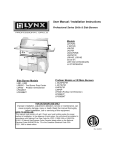
wings and attached
The
The duct and wings
will
vehicle will be designed to
determined altitude while the controller commands the four control
vanes that will maintain pitch, yaw, and
will then roll
over to horizontal
flight
speed and an improved endurance.
A
roll rates.
which
Once
at altitude the
will allow for an
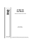
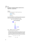
sketch of the vehicle
is
vehicle
increased forward
shown
in
Figure
1.
T OP VIEW
STDE
VTEW
AROD
Canard
Aquila Wings
Lower Body
Figure
1
:
Sketch of Archytas
8
THE DIGITAL CONTROL INTERFACE SYSTEM
III.
SYSTEM OVERVIEW
A.
The
of the Archytas vehicle requires a computer controller to
instability
control pitch, roll and
onboard sensors, and the
response.
The
original
ability to
AROD
With
this in
The
it
would have been
mind,
it
flexibility
then
digital controller requires input
command
a surface to generate the desired
This system was not used because
difficult to find interfacing
became necessary
to
develop a new
and low cost of personal computers
develop the system centered around an
IBM
to a personal
it
was
equipment for
it.
interface system.
made
it
personal computer. The
of Archytas will involve the vehicle in a hover.
ground linked
from
computer, a Motorola 68000 CPU, provided the
controller and interface functions.
outdated and
A
yaw motion.
desirable to
initial testing
This means the vehicle can be
computer through an umbilical.
The umbilical
will
allow the computer to sample and evaluate the sensor data. After the sensors' data
is
evaluated, the computer can then send a
umbilical to one or
more of
command
the four control vanes.
for vane angle through the
The umbilical
link can also
be used to control the
the
throttle servo
from the ground. Once
computer system can then be miniaturized
Enabling the computer
to
complete
special-function cards to the computer.
its
The
to allow
AM9513A
system
is
tasks required the addition of
first
The Quartz card
The card has
five
modes ranging A-X
expandable
to ten
two
card added (Diamond Systems
(PWMS)
is
to control the
a multi-purpose card with the
The chip
system timing controller as the main chip aboard the card.
has a versatile group of
proven,
onboard placement.
Quartz I/O) generates the Pulse-Width-Modulated Signal
four control vanes and throttle.
this
that are
shown
in the users
manual.
extremely versatile 16-bit counter groups.
Each group of counters has a wide variety of features, including up/down counting
by binary, or binary coded decimal, edge level gating, and a toggle output
capability.
The card has an
oscillator that can
internal series of frequencies derived
be exported.
from
a
1
MHZ
Additionally, the counter/timers can be used to
generate retriggerable one-shots of varying duty length.
A
list
of the card's
specifications and a pin diagram for the output port can be found in the users
manual.
The second card
installed is the
CIO-AD16jr card by Computerboards
provides sampling and analog-to-digital conversion.
open-ended input, or 8 differential input, card.
that provides a versatile
The card
Aboard
the card
that
is
a 16-channel
is
an 8254 chip
range of methods for triggering the conversion process.
10
The card converts from analog
to digital
conversion time of about 3 nanoseconds.
ability to
vary the input through various
A
by successive approximation with
useful feature the card provides
is
10V
ranges from a bipolar +/-
a
the
to a
unipolar 0-1. 25V.
The
final
systems to be engineered were the
included the umbilical and
utility
These systems
systems.
power systems. The power system included voltage
supply for the sensors, electronic ignition and a signal conditioning card.
This
A
major
system was
difficult to
design because of the diversity of each system.
difficulty in the design of the
the vehicle.
power system was
Additionally, the various systems
other as well as with the computer.
to
A
the need for
all
needed
it
to
fit
compactly on
to interface with
each
concern for the power system was the need
provide power to the various systems prior to the engine generator being up and
running.
A
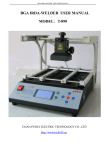
basic overview of the overall system
the basic systems
SYSTEMS
will
is
shown
in
Figure
SERVO CONTROL, ANALOG TO DIGITAL,
be described
in the following chapters.
11
2.
and
Each of
UTILITY
L0¥ER
OF
BODY
MOE
n
(0
<<
UTILITY SYSTEMS
UMBILICAL
Figure
2:
Basic Electrical System Design
12
IV.
A.
GENERATION OF THE SERVO CONTROL SIGNAL
GENERAL LAYOUT OF THE SERVO CONTROL AND QUARTZ I/O
CARD
The
digital controller
surfaces on the vehicle.
move each of
needs the ability to
The
original
AROD
command movement
design used Futaba S-134 servos to
These servos are general-purpose hobby
the four control surfaces.
The servos have
remote-control items that cost about $40.00 each.
(1) 5 volts; (2)
5-volt signal
ground; and
(3) a Pulse- Width-Modulated-Signal
powers a small
DC
of the control
three inputs:
(PWMS). The
motor, and the small amount of Transistor
Transistor Logic (TTL) onboard the device.
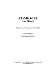
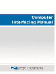
A PWMS
characterized by a
is
The
square wave whose duty cycle varies between 0.6 and 2.4 milliseconds.
width of the pulse drives the servo proportionally to the intended position.
narrow pulse of 0.6 milliseconds may drive the servo hard
right,
millisecond pulse will drive the servo proportionally less right,
millisecond pulse
may
every 10 milliseconds.
the
3
PC
provided the
shows a
typical
drive the servo hard
The
addition of the
ability to create the
PWMS.
The
left.
13
while a 1.0
and
is
a 2.4
refreshed
Diamond System Quartz I/O card
PWMS
user's
PWMS
The servo
to
command
manual for the
A
the servos.
to
Figure
Quartz I/O card was
VARIABLE PULSE WIDTH
5V
RISING
EDGE
>
<
FALLING
"EDGE
OV
REFRESH RATE
Figure
3:
10
ms
Pulse Width Modulated Signal (PWMS)
14
written with the intention of the card being used in conjunction with proprietor
This documentation was not adequate, or useful
software written in Basic or C.
PWMS.
in the generation of the desired
set
up count on a
"CALL"
"CALL"
This
is
mainly because the modes (A-X)
to a routine that is only
provided
to a subroutine is not explained in the card's
difficult to
understand exactly what
is
documentation, making
being done. Additionally, the
are only compatible with Microsoft C, not with Borland C.
routine
mode
was not provided,
into the
sheet for the
AM9513A
the card to be
the
AM9513A,
was necessary
it
chip
programmed
programming was done
to register-level
is
at register level to
in
Since the
program
The data
included in the manual.
Borland
C
to
it
C programs
"CALL"
the desired
onboard system timing controller chip.
the
This
in object code.
The data
sheet allowed
obtain the desired output.
All of
provide a robust environment for later
use.
To
allow the
ADDRESS
PC
to interface with the card, the first step is to set the
dip switches to a non-interfering address that the
For
interface with.
this application the
onboard dip switches.
The
BASE ADDRESS
location of the dip switches
C programs
225 hex was
on
BASE
the card
is
set
will
on the
shown
users manual.
This selects the base address of the port the program will write
or read from.
The card
each eight
bits,
is
in
to,
read and written to at one of three addresses which are
or one byte wide.
Table
15
1
describes each of the functions
The general
associated with the base addresses and their offsets.
AM9513A
registers' access
shown
is
The data bus multiplexor
ADDRESS + 1),
or the
address the binary
word
is
being written
will
between modes
The
to.
be loaded into
A
in
TABLE
1
:
through X.
WRITE
DATA REGISTER
CONTROL REGISTER
1
2
INTERRUPT ENABLE
4*
5*
*
depending on which
CONTROL PORT
determines
to select the operating
mode
The data
the desired
sheet
showed
DIGITAL OUTPUT PORT
9513 #2 DATA REGISTER
9513 #2 CONTROL REGISTER
PWMS.
READ
9513 #1 DATA REGISTER
STATUS REGISTER
DIGITAL INPUT PORT AND
INTERRUPT RESET
NO FUNCTION
9513 #2 DATA REGISTER
9513 #2 STATUS REGISTER
9513 #1
CHANNELS ARE ONLY USABLE IF CARD IS SET UP FOR 10
CHANNEL OPERATION BY ADDING THE SECOND AM9513A TO
THE CARD. NPS CARD IS NOT SET UP FOR 10-CHANNEL
OPERATION.
16
of
that
QUARTZ CARD INPUT/OUTPUT MAP
9513 #1
9513 #1
3
CONTROL PORT (BASE
any mode chosen from those offered
programming mode F allowed generation of
OFFSET FROM
BASE ADDRESS
4.
either the
selects
The card can be programmed
in the data sheet
Figure
DATA PORT (BASE ADDRESS),
which register incoming data
the card.
in
layout of the
Figure 4:
AM9513A
17
Register Access
B.
PROGRAMMING MODE
F
ON THE QUARTZ
Programming Overview
1.
To
AM9513A
enable the card to produce the desired
counters
Borland C.
programmed
is
C
Borland
must
the card, the card
for
mode
PWMS,
The programming
F.
number
first
be
to the output port desired.
Then
reset.
the
Master
To
Mode
programmed through each
(CMR). Each of the
five counters has
be programmed, called
The
desired signal.
LOAD
when loaded
LOAD
LOAD
The
and
and
HOLD
and
ms
LOAD
HOLD
HOLD
(MMR)
Then each of
two additional multi-purpose
Mode
must
the five
Register
registers that can
registers.
registers play
The
registers.
down
key roles
HOLD
to zero
refresh rate of the signal.
register.
in the generation of the
The
signal
is
register contains a
and
Once
fires a
18
that
down,
in the individual
LOAD
The count
between 0.6-2. 4ms.
its
one-shot high (5V)
number contained
held high until the
the desired pulse- width
number
the hold register counts
reaches zero, causing the one-shot to be reset (0V).
REGISTER creates
in
begin programming
counter's Counter
the counter is then toggled to be loaded with the
counters
done
individual channel counter alternates in being loaded from
in the counter counts
creating the 10
is all
Register
be programmed to control the overall function of the card.
counters must be
each of the five
has a function called "outportb(address, command)" that
outputs the 8-bit decimal
respective
CARD
I/O
register count
in the
LOAD
Varying the number
LOAD register varies the pulse-width. When the LOAD register counts
loaded in the
to zero the
count
counter toggles and
down
till
Most
part
command
command,
first
command
command,
is
available
DATA PORT
The
is
first
loaded through the
DATA POINTER
that
will
need
register,
to
CONTROL PORT
+ 1).
the Master
step to
Mode
Register
program any mode
command
step
is to
is
found
program
in
CONTROL PORT
possible selections of the
which shows how
Sending the
up the multiplexor
to
MMR.
to select the
Then
(MMR)
in the card is to reset the card.
to the
Figure
MMR.
the
writing 23 (binary 00010111), obtained from the
register to the
The second
entry into the appropriate register.
This reset
The next
sets
It is
DATA PORT,
be loaded.
accomplished by writing 255 (binary 11111111)
(base address
CONTROL PORT.
loaded in two 8-bit bytes through the
register
Programming
a.
for the Quartz I/O card are two-
points to the register to be loaded.
appropriate decimal equivalent to the
Reset
beginning the
of the Registers
is
Figure 5 shows the
access every
load the next
HOLD REGISTER
programming commands
that generally
a 16-bit
8 bits at a time.
to
Programming
register
commands. The
an 8-bit
loaded from the
the signal will be refreshed again.
Detailed
2.
is
CONTROL PORT
6.
This
is
accomplished by
DATA POINTER
MMR.
(Figure 5)
Figure 7 shows
the 16 bits of data are loaded into the
19
all
the
MMR
8 bits at a time through the
10110000)
is
Most of
PWMS,
The
first 8-bit
number 176 (binary
loaded followed by the second 8-bit 65 (binary 01000001).
assignment selects the
2.
DATA PORT.
This
bit
MMR (Figure 7) to operate in the manner described in Table
the selections in the
MMR
are arbitrary and have
but do need to be specified for operation of the card.
20
little
effect
on the
«
C7
cs
CS
04
C*
M
CI
u
r
r
CO
SMO
n
i
i
000
M
IV
f<
at
?
01
=~n
1
0«
000-
00
<
ll
<
00
<
/
Cy*o
01
to-
<
•
2
}
•0
J
•
0*01*1
QtoupZ
QroucJ
•
ConraCywinc
101
<
110
•
111
<
Orw»4
Orouei
'(No
Figure
TABLE
•
010
Oil
100<
(HOW C*e»t *cr*mm<t}
01
10
11<
001
2:
BIT
5:
Data Pointer Register
ASSIGNMENT FOR MASTER MODE REGISTER
BIT ASSIGNMENT
BITS
MM15,MM14,MM13,MM12
1011
MM11,MM10,MM9,MM8
MM7,MM6,MM5,MM4
0000
0100
FUNCTION
BCD DIV,DISABLE
INCR, 8BITBUS, FOUT ON
FOUT IS DIVIDED BY 16
FOUT SOURCE IS Fl MHZ
1
(FIGURE
MM3,MM2,MM1,MM0
0001
8)
DISABLE COMPARE AND
DISABLE TIME OF DAY
1
21
2
C*
C7
C4
ii
ca
C1
CO
a*
02
01
(0*000.
olEMS
o*noi
•1
•1
Si
Si
S1
Si
N2
N1
K3
N1
N2
N1
jj
Tgpjjj
cu SJQjj
far
9* (LOW)
lor
N (OOKN<101)
N (001 <N<101)
N (00KN<101)
tot
MM14
ft*
MMU
(Data
eft
WT)
m
%m MV13 (Era* i«-w
merM)
Oaarflaan Jtrmt* Oaa
S aaawcaaJ
MMH (Oa» on OUT)
MM11 (EflMr Mai toa
Figure
6:
AM9513A Command Summary
Sheet
w
OUT
0000 > f 1
or'
0001
on
*y*
*«
0010
*»*
•yo
0»7
•yo
0101
0110'
0111
1010
0010'
0011
"
'
0011
0100
-•NC1
-ones
-ones
-owe*
-owe*
0ATE1
-OATf »
MOO -OATf J
1001 -OATf 4
0110 •
0111
•¥»
1010
'
Syli
1011
'
1101
1110'
•»«
•»»
•/«
1111
kytt
1111 -
1011
1100'
1101
MMIS
•
MM
I
-OATES
• »1
1100 •
n
-us
1110
MMIS IMMttlMMII •M10
MM7
I
ma
I
mm2
I
-M
H
mmi
iMo
I
LI-
four*.
o-rouron
o-*o
1 -•OUT
-«o Oil
Figure
7:
Master
ZtoONO)
Mode
Register Bit Assignment
22
Programming of the Counter Mode Register (CMR)
b.
The Quartz I/O card and
Circuit (I.C.) has five
that control the servos that
five
PWMS.
1-5 to the
selects
need
change the vane positions.
Channel
movement on
DATA POINTER
the engine.
any of the five
register (Figure 5) through the
CMR.
The following example
all
five
PWMS
five outputs the
Therefore,
be programmed the same, and are done successively.
to
Integrated
Counters one through four output the
that controls the servo for throttle
CMR
AM9513A
programmable counters. The Archytas vehicle needs
counters to output the needed
PWMS
in particular the
all
Loading a
CONTROL PORT
illustrates the
process for
loading counter one; the other four are done in the same manner.
The
first
step in
CONTROL PORT
00000001)
in the
to load the
low and high bytes
loaded
The
bit
is
programming
to select
into the
CMR
CMR
one
counter one
via the
list
shown
in
CMR. The
DATA PORT.
98 (binary 01100010), and 27 (binary 00011011)
assignment
to load a
is
is
23
next step
The low
is
byte
the high byte loaded.
Figure 8 and Table 3 show the
causing various important actions to occur.
one (binary
CMR bit assignment
h wmmtm
•
•
•
•
•«•»
wet
met
-0 1
CMrt
OftTtt
• OATf
•0 •
1 -
I
MOD > OATt*
MM
•• -
**TI»
WW 0*H«
-
Mil
i«
1
•«
n
•
H
•
.0 >
1 •
• Pi
iwt *
1111
-
- OTC«
0t« •111
•0 •
1 •
TOn
WCl
Cm*
CMS
• 1
CM1
CMP
•M
•
•«-•<
»M^*
Mtfitl«MiaA'ttN*1
V*
- TCT«
M««hl«H>aATIN-1
•11
•
Miju
T«
w—igwtw
LMM««OATIN
110
in
111
Figure
TABLE
BIT
3:
8:
Counter
Mode
Register Bit Assignment
COUNTER MODE REGISTER
ASSIGNMENT
CM15,CM14,CM13,CM12
CM11,CM10,CM9,CM8
CM7,CM6,CM5,CM4
BITS
0001
1011
0110
BIT
ASSIGNMENT
FUNCTION
NO EXTERNAL GATING,
COUNT ON FALLING EDGE OF
CLOCK
COUNTER FREQUENCY SOURCE
IS Fl THE OSCILLATOR SEE
FIGURE 8
DIABLE SPECIAL GATE,
RELOAD FROM LOAD OR HOLD,
COUNT REPETITIVELY, COUNT
BINARY
CM3,CM2,CM1,CM0
0010
COUNT DOWN, WHEN TERMINAL
COUNT IS REACHED ON LOAD
REGISTER TOGGLE COUNT TO
THE HOLD REGISTER.
24
Most of
setting
This
is
is
the
above
settings are self explanatory.
that of the count being toggled
the heart of the
PWMS. As
loaded with a number that
between the
LOAD
and the
discussed previously, the
when counted
The most
HOLD
HOLD
critical
register.
register
out, refreshes the signal to the servo
firing a one-shot to a high voltage level (5V).
Once
counts out and resets the one-shot to a low value.
high, the
The number
LOAD
in the
is
by
register then
LOAD
register
translates to the variable pulse width desired.
c.
Programming of the
There are
counters,
counter
which need
LOAD
LOAD
and
HOLD
registers can be accomplished
CONTROL PORT.
As
The
Registers
registers
The
by writing a 9-13
initial
is
new number
its
(binary 00001001
value loaded
is
through the
loaded with a high and low byte
is
a zero deflection angle of the
loaded into the
To change
the position
LOAD REGISTER.
will be translated into a different width signal,
servo to change
which
is
This
then sent to the
position at a refresh rate of 10 ms.
The
of any of the
new number
of the five
selection of any of the five
PWMS translated to the servo that controls the vehicle vanes.
of one of the five servos a
for each
DATA POINTER register (Figure 5)
before, the register
DATA PORT.
HOLD
and
be loaded successively.
to
through 00001 101) as shown on the
through the
LOAD
HOLD
HOLD
registers
registers are also loaded successively.
is
The
selection
accomplished by loading a 17-21 (binary 00010001
25
through 00010101) into the
as
shown
in Figure 5.
is
Once
this is
DATA PORT.
as data into the
register
DATA POINTER register through the CONTROL PORT
accomplished, the low and high bytes are loaded
For the purpose of generating the
loaded with a value that makes the
PWMS,
refresh rate for
all
the
HOLD
five channels
approximately 10 ms.
3.
Final
The
load and
arm
Programming Notes
final
counters will begin to operate.
In
command
These programming steps
is
is to
can be seen that when a
CONTROL PORT
all
will allow the counter to
to generate the
for user interface to determine
change of angle
is
number
Quartz I/O card
given.
program allows
angle input to a
it
loaded into the
is
Appendix A, a program used
desired.
initialize the
In reference to Figure 6,
decimal 127 number (binary 01111111)
operate until a disarm
Mode F
event that must occur to
counters.
all
for
One equation
is
PWMS
is
given.
The
which counter and how much of a
used in the program to convert a degree
to load into the load register to obtain the desired pulse-
width.
26
PROGRAMMING THE COMPUTERBOARD'S ANALOG-TO-DIGITAL
CARD
V.
COMPUTERBOARDS ANALOG-TO DIGITAL CARD OVERVIEW
A.
With
the
programming of
The next
vehicle.
step in the
the Quartz card
we have
development of the
digital controller is a
convert the onboard sensor information to digital form. This
the use of the
card
is
the ability to control the
is
method
to
accomplished through
Computerboard CIO-AD16Jr 16-channel analog-to-digital
card.
The
versatile 12-bit converter with variable crystal settings, eight differential or
sixteen single-ended channels, and a
programmable input voltage range.
Similar to that for the Quartz card, the user's manual for this card
is
designed to be used with proprietor software. For the purpose needed, seven of the
manual's
to
84 pages contain useful, but incomplete information.
the fact that the proprietor software
subroutine
is
used in every
mode
provided in other than object code.
is
provided in Basic.
that requires a
To
function
This
is
partly due
Additionally,
"CALL"
that is not
use the card for the purpose needed
necessary to obtain the onboard counter/timer data sheet (Intel 8254),
experiment with many of the
a
it
was
and
to
settings.
Prior to the card being installed in the computer, the board must be strapped
for a non-interfering address.
For
this application the
27
address was strapped for 300
hex.
The
additional address options can be found by referring to users manual.
addition to the address setting, the card
channel single-ended input.
relevant since a
IBM
The card
is
was strapped
386 machine handles memory
programmed
The card allows
in
Borland
is
M
for register level
addresses that provide various functions.
used
1
MHZ
operation and 16-
The Direct Memory Address switch
"inportb(address)" and "outportb(address,data)
addresses.
for
The
C
In
selection
is
not
transfers.
using
the
library
which allow access
functions
to external port
programming through
sixteen 8-bit
analog-to-digital conversion
method
successive approximation with each conversion taking approximately 3
nanoseconds. The input signal
of the function of each address
is
is
converted to a 12-bit digital number.
shown below
28
in
Figure
9.
A
summary
ADDRESS
BASE
BASE +
BASE + 2
BASE + 3
1
READ FUNCTION
A/D
Bits 9
-
12(LSB)
WRITE FUNCTION
&
Stan A/D Conversion
Channel #
None
A/DBits l(MSB)-8
Channel
Digital
MUX Set
Channel
4 Bit Input
MUX Read
Digital 4 Bit Output
BASE + 4
None
None
BASE +
5
None
None
BASE +
6
None
None
BASE +
7
None
None 21
BASE +
8
Status
BASE +
9
DMA, Interrupt &Trigger Control
Set
BASE +
10
Pacer clock control register.
None
BASE +
11
Gain
Gain control
EOC, UN1/BIP etc.
None
setting read-back.
DMA, INT etc
BASE +12
Counter
BASE +13
BASE+ 14
CTR
1
Data
-
A/D
Pacer Clock
CTR
CTR
2 Data
-
A/D
Pacer Clock
CTR 2 Data A/D Pacer
BASE +15
None.
Counter
Data
No read
Data
-
A/D Pacer
-
Pacer Clock Control (8254)
back on 8254.
Figure
1
Data
9:
A/D Card Address Overview
29
PROGRAMMING THE
B.
Programming
A/D
CARD
the card requires the initialization of several of the addresses
The
from Figure 9 for various desired modes.
Multiplexor
the
(MUX). The
number of channels
channel desired
(i.e.,
to
MUX
first initialization
MUX
The
can have various functions.
be incremented through, or be used to point
0-15).
The
MUX
also
is
that of the
is
can
set
up
at a specific
the device that points to the current
channel, and increments to the next channel to be converted.
The conversion process
can be started in one of three ways, by software trigger, external trigger, or internal
pacer clock trigger. The
read.
This
is
MUX also can be used to reset to the desired channel to be
done by writing
to the
MUX
contain the channel desired for conversion.
in
where the upper 4
The
layout of the
bits
of the
MUX register
is
MUX
shown
Figure 10.
The
MUX
register
is
divided into two halves.
The lower
half (bits 0-3) of
The upper
half (bits 4-7) of
the register selects the starting channel to be converted.
the register selects the ending channel.
converted.
Then, when triggered, the
The
MUX
MUX
points at the channel currently
increments
itself
register to the next channel to be converted in a continuous loop.
register sets the
number
STATUS
register channel and current
in bits 4-7.
30
A/D
and the
STATUS
Every write
to this
MUX
to the
channel
BASE ADDRESS +
7
6
CH
**
L
4
5
CHH8 CHH4
*
2
CHH2
CHH1
**
refers to channel
refers to
2
3
H
CHL8
CHL4
1
CHL2
CHL1
refers to high channel
low channel
Figure 10: Set up of the Multiplexor register
The next address
be initialized
to
the analog input range.
is
channels can only input the selected voltage range.
of the
1 1
many
The
.
values
shown
in
Table
4.
The
selection of the appropriate bits
selects the desired input voltage range.
This range
for the current configuration.
00000101)
to
base address
+
layout of the register
is
to
voltage range of 0-5 V
is
shown
in Figure
base address
is
5
4
X
X
X
X
Figure
1 1
:
3
RANG
2
UNI/B
Analog Input Range Register
31
11
setup by writing a decimal five (binary
BASE ADDRESS +11
6
+
the input range
11.
7
A/D
The voltage range can be one
from Table 4 written
A
All sixteen
1
Gl
GO
TABLE
RANGE
BIT SELECTION
4:
UNI/BI
FOR ANALOG INPUT RANGE
GO
Gl
INPUT
RNG
+ - 10V
1
+ -5V
1
+ - 1.25V
1
1
1
+
-
.625V
0-1 ov
1
1
****
+ -2.5V
1
1
1
1
1
0-5V ****
0-2. 5V
1
SELECTED RANGE FOR THE APPLICATION
32
0-1. 25V
The next address
initialized is
Memory Access (DMA),
Direct
program
to store the
location.
Although
BASE ADDRESS + 9
is
DMA
and trigger control.
interrupt,
most recently converted channels
DMA
which controls
not used during this
in a specific
application,
considered for later development to increase operating speeds.
allows the
PC memory
DMA
should be
BASE ADDRESS +9
allows the selection of interrupts two through seven and allows them to be
onto the
PC
conversion trigger can be selected
control register
is
shown
BASE ADDRESS +
7
INTE
5
4
3
IR4
IR2
IR1
X
set to
desired interrupt.
1).
The
DMA,
the
bits,
interrupt and trigger
9
6
Selecting
INTE
and
(bits
mapped
Figure 12.
in
Figure 12:
while
by the selection of the appropriate
Additionally,
bus.
the
INTE = 1
DMA,
(bit 7)
2
1
DMA
TS1
TSO
Interupt and Trigger Control
enables interrupts to
zero disables interrupts.
be placed on the
Bits 4-6 select the binary
bus,
number of
Interrupts zero and one cannot be asserted if selected;
33
PC
the
these are
these are reserved for the
selected;
to
PC memory,
while a zero in
PC.
bit
Selecting
two disables
important because they select the source of the
start selections are listed in
TABLE
5:
1
allows
Bits zero
conversion
5.
METHOD
which the
"SOFTWARE TRIGGERED A/D"
number
MUX
is
to the
pointed
address
at
to
be converted to
digital signal placed
which the
MUX
is
BASE ADDRESS.
selection allows for the conversions to be
edge
(pin 25)
START ON PACER CLOCK PULSE (CTR2
1
writing any
and one are
The conversion
start.
START ON RISING EDGE TRIGGER
If
storage
SOFTWARE TRIGGERED A/D
1
1
DMA
TRIGGER METOD
X
rising
DMA.
A/D START CONVERSION
TSO
TS1
Table
A/D
DMA =
is
selected, the conversion
begun by
This causes the current address
its
12-bit digital form.
pointing to be converted.
selection utilizes the onboard pacer clock and
The
The
rising
at
The second
"EXTERNALLY TRIGGERED"
on pin 25 of the card.
34
is
out)
by a
edge causes the
final start
two onboard counters
conversion
to control the
conversion.
In this
conversion.
In this
causing the
start
mode
mode
counters
counter
1
is
1
The
of conversion.
and 2 can be used
to set the
frequency of
used serially in conjunction with counter 2
rising
edge of counter 2's output square wave
triggers the start of conversion.
The next
five registers all
work
shows the interrelationship of these
in conjunction with
five registers,
Figure 13
each other.
and Figures 14 through 18 show
the layout of each register.
GATEO
CONTROL REGISTER
BASE
+
10
CTR
IN
CTR
#—
{
A/D
PACER
PACER CLOCK
35
Control Register
2
OUT
,
25
Figure 13:
CTR
20
OUT
)
TRIGGER
BASE ADDRESS +
10
7
6
5
4
3
2
1
X
X
X
X
X
X
CTRO
Figure 14:
BASE ADDRESS +
PACER CLOCK
Control Register
15
7
6
5
4
3
2
1
SCI
SCO
RW1
RWO
BCD2
M2
Ml
Figure 15:
BASE ADDRESS +
CTR1
MO
COUNTER CONTROL
12
7
6
5
•4
3
2
1
D8
D7
D6
D5
D4
D3
D2
Figure 16:
COUNTER
36
Dl
BASE ADDRESS +
13
7
6
5
4
3
2
1
D8
D7
D6
D5
D4
D3
D2
Figure 17:
COUNTER
Dl
1
BASE ADDRESS +14
7
6
5
4
3
2
1
D8
D7
D6
D5
D4
D3
D2
Figure 18:
The
the interface
timer
PACER CLOCK
COUNTER
control register
(PACER CLOCK). The
2
BASE ADDRESS + 10
between the board functions and the
Dl
Intel
(Figure 14)
8254 programmable
is
interval
remaining four registers are resident onboard the 8254
and are accessible from the addresses shown.
37
Programming
the
PACER CLOCK
control register consists of four possibilities.
is
CTR0=0
and
TRIG0 = 1.
control the start conversion.
The
selection for the purpose desired
This selection allows the
If desired this
connector to affect the conversion. The pin
mode
2 output
to
also allows pin 25 of the cards
pulled up to
is
COUNTER
+ 5V,
and will always be
high unless an external connection to pin 25 pulls the pin low which would disable
conversion.
The remaining
selecting
15).
COUNTERS
them through commands
Additionally,
CONTROL
register.
from the 8254 data
application
is
mode
To
internal to the
1
8254
From
sheet.
three.
the
must be selected
mode
selected for this
the data sheet the desired
COUNTER
1
1XXXX
(X
at the
and
indicates
it
COUNTER
it is
Loading
frequency
2.
must point a multiplexor
COUNTER
1
requires a binary
does not matter which binary number) to be written to the
COUNTER CONTROL register (BASE ADDRESS +
(refer to Figure 15) select the desired register.
which stands for
at a
necessary to refer to the 8254
COUNTER CONTROL
desired counter.
COUNTER
PACER CLOCK
This selects a repeating square wave
load a counter, the
8254
register (Figure
up through the
set
is
load any of the 8254 onboard registers,
data sheet.
01
the
2 can be loaded by
COUNTER CONTROL
The operating mode of
determined by numbers loaded in
To
to the
mode of
the
COUNTER
through
READ WRITE)
select a
Bits
15). Bits
RW1 =
1
SC0=0 and SCI =
and
1
RW0=1 (RW
loading scheme for the desired register,
38
most significant byte.
in this case the least significant byte first, then the
COUNTER 2 binary
Bits
Once
COUNTER 2.
select
The counters
square wave which
are loaded with
is
The read/write
numbers
must be loaded with a value
manner
to
to
Mode
produce the desired output.
M2=X, Ml =
1
and
M0=1
wave
is
loaded
select
COUNTER
to the
3
bits
to
complete, the
is
be
10
MUX
milliseconds
accomplished by setting up the card for
into
COUNTER 2.
and
1
wave whose
COUNTER
2.
BASE ADDRESS + 15
of
sheet,
RW1
and
To
the
RWO,
COUNTER CONTROL
which from the 8254 data sheet produces
begins sequencing through the
desired channels scanning one channel per rising edge.
numbers
COUNTER CONTROL
8254 data
The
first.
mode
1].
output.
initialization
was established
three create a 10
3 produces a square
loaded into
is
With Reference
which byte
the desired square
Once
XXI 1X1 10
a binary
COUNTER CONTROL.
select as before
previously
enable the 8254 to operate in the desired
frequency depends on the values loaded in
rate
make mode
that
the registers are loaded with values, then the
mode
bits are as
the desired sampling rate for the control laws' [Ref
register
select this
select
1XXXX is loaded into the COUNTER CONTROL register.
SC0 = 1 and SCI =0
described.
ms
101
To
COUNTERS
The output of
1
and 2
[Ref
The
1].
control laws' sampling
This
sampling rate
"EXTERNAL TRIGGER". Then
that
COUNTER
2
39
create
is
a
10
ms
is
loading
square wave out of
then be fed into pin 25 of the card to
provide the rising edge of the
rate.
This method
is
"EXTERNAL TRIGGER"
in
Appendix B
to
"SOFTWARE TRIGGERED MODE",
polls the interrupt bit
The programmed software allows
This
channels to be converted.
trigger control being returned to
trigger
is
to the
changed back
to
is
till
the
set,
STATUS REGISTER. The
then the
to allow
MUX
mode of conversion
to point at the desired
done prior
.
register.
After the channel
is
changed
the
number of
interrupt
After the interrupt
"EXTERNAL TRIGGER",
is
program
being cleared and
to the interrupt
"EXTERNAL TRIGGER" The
STATUS
not
conversion of the other channels.
MUX
is
is
cleared
cleared and the
increments to the
next channel to be scanned and waits for the next rising edge from
base address and
mode does
preferred over Pacer Clock driven because that
produce an interupt that can be polled from the
by writing any value
for the desired sampling
COUNTER
2.
converted, the value can be read and assembled from
BASE ADDRESS +
1.
The
20.
40
registers are
shown
in
Figure 19 and
BASE ADDRESS
7
6
A/D9
A/D10
4
5
A/D12
A/Dll
3
2
1
CH8
CH4
CH2
CHI
LSB
Figure 19:
BASE ADDRESS +
7
A/Dl
A/D LSB Data
and Channel Register
1
6
5
4
3
2
1
A/D2
A/D3
A/D4
A/D5
A/D6
A/D7
A/D8
MSB
Figure 20:
As shown
in Figure 19, the
lower four
channel that has been converted.
Bit
bits
of the converted channel.
is
bits
of the
The upper four
(LSB) of the converted channel.
function "inportb(address)"
A/D MSB DATA
BASE ADDRESS
bits contain the
BASE ADDRESS +1
To assemble
Least Significant
contains the upper eight
the complete 12-bit
word Borland C
used to read the two register addresses.
41
contain the
Then
the
BASE ADDRESS
contents read from the
The
channel number, and leave the LSB.
(Figure 20) are then rolled
left
four bits to
two numbers, they are bitwise ORed
are rolled right four bits to
to
contents read from
make room
make
for the
remove
the
BASE ADDRESS +
LSB. To assemble
1
the
the complete 12-bit word. This process
takes the inputted analog signal and converts the signal to a digital
number between
0-4096.
The
final register that has
(BASE ADDRESS +
BASE ADDRESS +
7
6
EOC
U/B
8).
The
many convenient
STATUS
register
is
uses
is
the
shown
in
STATUS REGISTER
Figure 21.
8
5
MUX
4
3
2
1
INT
CH8
CH4
CH2
CHI
Figure 21: Status Register
The most
significant bit of the
conversion has been received;
conversion complete.
unipolar (U/B =
l),
STATUS
EOC =
The next
bit
1
register
EOC
indicates that the end of
means busy converting, while
U/B
or bipolar (U/B=0).
tells
MUX
42
EOC =0 means
whether the input amplifier
bit tells
is
in
whether the input channels
are single-ended or differential.
received on pin 25;
This
received.
sampling
the
A
rate,
CPU. The
program
bit
and
INT =
The INT
means no
bit tells
whether an external pulse has been
pulse, and
INT=1 means
can be conveniently used for polling
later applications
final four bits tell at
to set
that converts input channels
from analog
Appendix B.
43
MUX
is
to digital
been
up the control law
can be placed on the internal
which channel the
a pulse has
PC
bus
to free
up
currently pointed.
is
included in the
VI.
A.
UTILITY SYSTEM OVERVIEW
The
vehicle.
UTILITY SYSTEM
utility
system incorporates many diverse systems on the
In general the utility systems include the systems needed to
sensors, control system servos, and the electronic ignition.
includes a method
commands from
getting
for
the
computer
signals
from the sensors
to the vehicle.
Archytas
power
the
Additionally the system
to
the
computer, and
All of these systems have to be
contained compactly and securely in a housing aboard the vehicle.
When NPS
received the
which each contained
all
AROD
vehicles they contained two forebody units
the electronics to operate the vehicles.
documentation was received, or available.
Unfortunately no
Observations of the units'
complicated
wiring coupled with no schematics made the aspect of using the existing wiring
impossible.
With
mind
this in
the tasks
were
to gather the data sheets
on the sensors
and establish what power systems were available and engineer a new system.
other task was to
make
The
the utility housing self contained and able to be attached to
both the vehicle and the umbilical.
The
direction taken
was
to get
connected. This control system would
one control system
roll-rate
completely
unmask many hidden hardware problems and
44
make
the
the addition of other sensor connections easier.
power
for ignition,
power and
The systems connected were
signal for servos, and the
power and
signal
connections for the roll-rate sensor.
One of
the first steps in the process
was
to adapt the
housing
to the vehicle.
Since the early tests are to be done with the vehicle attached to the umbilical, the
housing was designed to be attached to the bottom of the vehicle between the vanes.
This additionally provides a degree of
stability.
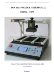
Figure 22 shows the housing
attached to the vehicle; Figure 23 shows the housing alone.
45
Figure 22: Housing Attached to the Vehicle
46
Figure 23: Housing Unit Power Routing and Connection
47
Power Routing and Connection
1.
The next
From
requirements.
various
DC-to-DC
was
step
to
the original
begin routing power to meet each system's
AROD
configuration the housing unit contained
These are
converters.
whose output
units
is
a specified constant
once the input reaches a certain minimum value. The configuration from the original
AROD
comes with power
supplies
electronic ignition, and servos.
+ 12V,
+/- 15V, and +28V.
power supply
to the servos
through Futaba
J
is
connectors
can conveniently power the
that
Available power supplies on the unit are +/- 5V,
As shown on
+ 5V.
(to
sensors,
This
is
the schematic in
Appendix D,
wired directly from a
+5V
the
converter
allow disconnection for housing removal) to the five
S-134 Futaba servos.
The
from the
ground,
is
electronic ignition for the engine requires
+ 28V DC
+28V
converter through a Futaba
and a return
line for the
G connector.
+28V.
This
The connector
sheet
is
in
Appendix C, and picture
wired
contains
tachometer from the electronic ignition which
routed back through to the umbilical to allow measurement of engine
The only sensor wired up
is
is
is
the single axis roll-rate sensor
shown
in
Figure 24 and 25.
RPM.
whose data
Wiring
this
control system sensor allowed the connection of the output of the sensor through a
conditioning card to the umbilical ending up
at the
from the vehicle
The
in
computer-usable form.
48
A/D
card which provides the input
control laws can then be applied to
the vehicle input.
The computer can then generate
from the Quartz I/O card and send
correct the vehicle's roll-rate.
sensor
to
is
it
PWMS
the correct
back through the umbilical
The sensor
requires +/-
15V
to
for the vehicle
to the
power
connected to the appropriate power supply through a Futaba
allow removal of the sensor from the housing.
The data
G
servos to
up.
This
connector
sheets for the remaining
sensors that will require installation are included in Appendix
C
along with pictures
of each.
The next
the vehicle to receive
step in the
hardware connections was
power from
externally until engine ignition.
the
The
fit
provide a means for
onboard generator, or have power provided
original
AROD
had a card with a group of
diodes arranged in a fashion to allow dual power sourcing.
to
to
This card was adapted
inside the housing and wired to allow external connection for
plugs, and wired to the onboard generator.
power through
This card allowed external power
connection to power servos, ignition, and sensors prior to the engine running.
the engine
is
running and the generator
is
After
supplying power, the external connections
can be removed to provide the ability for independent
49
flight.
Figure 24: Roll-Rate Sensor in Housing
50
Figure 25: Roll-Rate Sensor (lower) Pitch and
51
Yaw
Sensor (upper)
Signal Connection and Routing
2.
Once power
be connected.
at the
in the
applied to each of the devices, the controlling signal must
The servos each
computer.
Then
connector.
is
This
is
require a
PWMS
to
be connected that
is
originated
accomplished by connections from the umbilical through a
the signal
is
routed through the housing and joined as the third wire
Futaba J connectors that connect the power to each servo. This means
that the
+5V
servos are each connected to a 3-wire Futaba J connector that contains ground,
and a
PWMS.
This connection
The connected
correlates to
shown on
is
roll-rate
sensor signal output
+/-100 degrees/second of
conditioned to the 0-5V range that the
from the
roll-rate sensor is sent
developed by
AROD
roll rate.
A/D
card
from the sensor
Once
engineers.
necessary voltage range of 0-5V,
the schematic in
This outputed
is
set
to a
up
is
+/-2.5
a
is
roll rate
to convert.
VDC
needs
The
that
to
be
signal
conditioning card that was
the sensor output
the signal
Appendix D.
then routed
is
conditioned to the
to the umbilical
through
connectors as shown on the schematic in Appendix D.
The umbilical provides
to control the servos.
and
to
to the vehicle
the
means of sending
the
PWMS
to the vehicle
Additionally, the umbilical provides routing for the roll-rate
sensor signal and the tachometer.
connected
a
The umbilical
is
an unshielded cable that
through a cannon plug on the housing shown
computer by connections shown
52
in
Figures 27 and 28.
in
is
Figure 26,
Figures 27 and
28 show the cables run from the
in the
computer.
roll-rate
and
Additionally
throttle.
A/D
shown
card and the Quartz I/O card that are installed
in
both figures
The terminal block shown
in
is
the joy stick that
both figures
commands
allows connection
of the Umbilical to both cables. The breadboard has a unity gain amplifier wired that
was used
to protect the
Quartz card outputs which did not have, but needed buffered
outputs.
53
Figure 26: Umbilical Connection to Housing
54
Figure 27: Umbilical Connection to Computer
55
Figure 28: Umbilical Connection
56
to
Computer
VII.
A.
SYSTEM TESTING, CONCLUSIONS AND RECOMMENDATIONS
SYSTEM TESTING
Testing of the various systems has occurred
The
ability to control
movement of
the vanes
various stages of the project.
at
became important and was
tested
when
and torque measurements were needed during the summer of 1992. The
static thrust
Archytas vehicle
test
move
stand allowed the computer to
through the umbilical during engine operation. The ability to
and one or
all
the vanes and throttle
command
the throttle,
four vanes incrementally was instrumental in making accurate
measurements of the desired parameter.
The A/D system was
the
Futaba S-134 servos
tested
and utilized when
that control the
the
became necessary
to
model
vanes to determine the frequency response
for incorporation in the control laws [Ref
was accomplished by commanding
it
1].
The
data gathered for the modeling
a unit impulse signal into the
programmed A/D card allowed sampling of
the
S-134 servo. Then
position
of the feedback
potentiometer inside the servo.
Additionally the complete roll-rate system
incorporates the software control laws [Ref
and
utility
systems.
1]
into the
is
being tested.
The system
hardware A/D, servo control,
Early hardware problems continue to be resolved to allow
57
complete
testing.
As with
functional systems, the addition of any individually
all
engineered system to other individually engineered systems
is
not accomplished
without further modifications.
CONCLUSIONS
B.
The desired goal of this
for the Archytas
to
hover
to
UAV.
altitude,
This vehicle
command
is
a
was
VTOL
to create a digital interface
fixeu .ving airplane that
then transition to horizontal flight.
establish a complete system to
useable form,
investigation
is
system
designed
The emphasis was
to
convert onboard sensor information into computer-
then allow the information, once processed, to output a signal to
attitude-controlling
servos on the vehicle to control pitch,
yaw and
roll.
This investigation accomplished the following:
• The addition of a Quartz I/O card added to the PC and programming
a Pulse- Width-Modulated Signal to control servos.
to create
• The addition and programming of the Computerboards Analog-to-Digital card
that sampled at the desired controller rate, and converted the inputed signals to
a 12-bit digital useable signal.
•
A
was developed that attaches to the bottom of the
Archytas vehicle and contains power supplies that allow operation of the rollrate sensor, servos and the electronic ignition for the engine.
These power
supplies can operate prior to engine ignition on external power, and after
ignition on the engine's generator.
self-contained housing
58
Problems developed
systems.
in several areas
The servos were deemed
controlling the vanes.
real possibility.
The servos
The umbilical
during the development of the above
be have limitations for the purpose of
to
limited torque, and plastic gears
cable
was determined
to
make
failure a
have noise spikes traversing
the cable to the point of shorting the output amplifiers on the
AM9513A
(Quartz I/O
card) causing replacement of the chip. This problem led to the addition of a unity
gain amplifier installed in line with the cable to protect the computer card.
The
conditioning card schematics obtained from Sandia Laboratories were determined to
be inaccurate and require further investigation for use with the remaining sensors.
With any physically controlled and controllable system much time can be spent
adjusting programs and locating bugs that cause unwanted behavior.
of wiring adds the additional problems of unwanted noise,
sometimes bad connections.
Overcoming
The addition
and imperfect
or
these types of problems provide the best
real-world lessons and a feeling of accomplishment.
59
RECOMMENDATIONS
C.
In continuing
include
work toward
a fully-flyable vehicle, specific recommendations
:
• Addition of the remaining sensors, and incorporation of the remaining control
laws for
stability.
• Obtaining a shielded umbilical cable
• The purchase of adequate servos
to
remove
the noise problems.
that operate off
PWMS
and develop adequate
torque for the given job.
• Investigating
obtaining
CPU
all
the addition of
DMA to the Computerboards A/D card to facilitate
sampled channels quicker.
This would additionally free up the
time.
• Establishing an interrupt system that will be generated from the Computerboards
A/D card and placed on the PC bus. This would eliminate the need for polling
and release the CPU to accomplish other functions.
• Development of a three-axis test stand that will allow testing of all axes of
motion on the vehicle housing to establish validity of the control laws applied
to the utility system.
60
APPENDIX
PROGRAM GENERATES PWMS
A:
/*
Written by: Lt. Paul
Revised:
'
Merz
11/29/92
For: Masters Thesis applied to the Archytas air vehicle
This program
is
written in Borland
The program
2.0.
utilizes the
Pulse-Width -Modulated signals
.6 to
2.4 ms.
counters and
The
signal
is
C compiled
and run
Quartz I/O card
(PWMS)
in version
to generate
of varying duty cycles from
produced out of
all
5 of the cards
designed to vary the position of any servo connected
is
The program
to the counters.
is
designed to be user driven with
the following servo connections:
+ 5v
pin 49 to red wire of servo
gnd pin 50
PWMS
To
to
black wire of servo
any of pins 5,11,17,23 or 39
operate the card must be strapped prior to installation for the
address that will be declared as "datreg".
Ref: Quartz I/O User's
#include<dos.h>
//include <stdio.h>
int
datreg
=
*,
Manual
*/
/* preprocessor control lines: 'include'
/*
inserts a
copy of
<*.h>
/* declare 'datreg' this
544;
is
at this
point
the base address
strapped prior to card
installation
int
conreg
main()
<..
=
545;
*/
*/
/^declare 'conreg' as integer value 545
/* functn 'main' executes
main body of program*/
.
initialize();
chgangle();
/* functn calls 'initialize'sets
up registers
*/
/* functn 'chgangle' executes endless loop to
*/
vane positions
}
61
change
^
^
^^
b^
i^ *J^
iltf iitf
*T* *T* *T* *T* *T* *T* *T* *T* 'T* *T*
/^J<?
iJtf
T*
5j£
s
I
^Itf 5itf iJtf iltf iltf iltf
•Is *T*
1*
iJtf ^Jtf ^Jtf 5>tf iJtf iJtf bltf
*v* *T* *T* *T* *T*
T*
*T»
T*
•T* *T*
^
T*
iJtf iJtf iJtf
*T»
*P T*
^tf 5Jtf il^
*T* *T* *T*
^^
T*
^Jtf ^Itf
^ ^ ^ ^ ^ ^ "^
i^ S^ T*
*T" "T* *T* *T* "T*
^
^" ^f "4r *& *^ "A" -i* -it* -il* »X*
^A»
*T* *T* ^v* *T* "T* *T* *T* *T* •T* *T* *T* "T* *T* »T* *T* *T* 'T' *T*
"st*
*^
>t» *X» *A» «X» *X- «X» «X» «A» st» -s>
*T* *^ *P- *T^ 'T* •T* *!* *T^ *S *|>
*/
/* changle
number
is
a subroutine that converts a user input into a integer
that
can be placed
in the load register to
change the width
The software allows
of the outputed pulse width.
the selection of
any of the 5 channels on the Quartz card. After selection the user
inputs an integer number that will be converted to a change in PWMS.*/
/**?
*T*
^if *.** *Ji* ^X* %lg *J#
*T* *T* *T* ^* *T* ^^
^Itf
^^
^j^
*X* *X* *A* *X* *X* *X* *X»
^* ^^
^* *X*
^* ^*
*^ ^* *X*
^* *X*
'^ ^^
^* ^^ ^n ^^ ^^ *^
*X* iitf
*T*
*X* *X*
% ^*
^
sit* *X* ^X* *X*
^^ ^^ *^ *^
*L» *X* *X* *X^ *Xr *X*
%
*T* ^^ ^* *^ *T*
^
"*X*
^*
*X* ^X/ *X* *X* *X* *X» *X*
*T* *^ ^^ ^^ ^* ^* ^^
*i* vi^ ^x* %
*^* "4* *w*
v
*-'*
,v
chgangle()
{
int i,hibyte,lobyte, angle, cmnd, vane; /*
angle =
/* since angle
l;
while (angle
>
/*
0)
declare variables as integers */
>
always
*/
0, this causes
*/
endless loop
{
printf("ENTER
THE VANE NUMBER TO CHANGE
scanf("%d",&vane);
vane=vane + 8;
/* inputs the value of
TO
vane between
1
5\n");
&
*/
5
adding 8 changes the binary value so that*/
'vane' can be used to label an address */
/*that
printf("ENTER
1
/*
/*
*/
translatable to a counter
is
THE DESIRED ANGLE
\n
*');
/* input the desired
scanf("%d",&angle);
vane angle
in
degrees */
angle = ((1 900/206) *angle + 600);
= (angle/256);
lobyte = (angle-hibyte*256);
cmnd = 193;
forms high byte
/* forms low byte
/*
outportb(conreg,cmnd);
between 9
13= 0000 1001b
*/
&
0000 1101b*/
/* select load register of desired counter */
*/
outportb(datreg,hibyte); /* upper byte of # to load reg
*/
outportb(conreg,cmnd);
cmnd = 97;
/*
233
=
/*
97
*/
1110 1001b
/* sets toggle high for counter
= 0110 0001b
62
*/
*/
outportb(datreg,lobyte); /* lower byte of # to load reg
cmnd = 233;
#
*/
=
&
to dig
*/
1100 0001b
disarms counter 1
/* 193
outportb(conreg,cmnd);
/*
conv fm deg
/*
hibyte
cmnd=vane;
/* algorithm to
*
'*
**x* ^tf *X* *X*
' *X*
*X*
X* X* *X* X* *X* *X* *X* *X* *X*
^p ^^ ^^ *^ ^^ ^^ ^^ ^n *^ ^^ ^^ ^^ ^* ^^ ^^ ^N ^^ ^N n\ ^p ^^ '^ ^p ^p ^p
*/
1
*/
'
* '*
~
outportb(conreg,cmnd);
1
*/
/*end while*/
}
}
(fm load reg) and arms counter
/* loads
/*end chgangle*/
/* Initialize sets
up the Quartz card
PWMS
allows the card to generate the
up various other functions
the purpose of the archytas
it
mode
to operate in
out of
all
which
5 counters,
that are not
also sets
j
used for
*/
initialize^)
!
cmnd,i;
int
printf("start of process\n");
cmnd=255;
/*
outportb(conreg,cmnd);
cmnd=23;
/*
cmnd = 65;
0001 0111b
select master mode register
/* 176
outportb(datreg,cmnd);
/*
/*
*/
board functions
=
23
/*
*/
1111 1111b
/* resets all
outportb(conreg,cmnd);
cmnd = 176;
=
255
=
*/
*/
1011 0000b
*/
low byte: FOUT source
65 = 0100 0001b
is
*/
Fl
*/
/* high byte: binary division,
outportb(datreg,cmnd);
disable increment,
8-bit bus width,
FOUT
MODE
j
'J'
|
on, divide by
*/
1
|
cmnd=249;
/*
outportb(conreg,cmnd);
for
(i
249
=
*/
1111 1001b
/* disable prefetch for write operations
*/
= l;i< =5;i++)
{
cmnd = i;
= 0000 0001b
0000 0101b
outportb(conreg,cmnd); /^select ctr mode reg of group 1 thru 5
*/
/* 98 =0110 0010b
cmnd=98;
outportb(datreg,cmnd); /* low byte: disable special gate,
reload from load or hold,
/*
1
to 5
count repetitively,
binary count,
count down,
63
to
*/
*/
TC
cmnd=27;
*/
toggled
=0001
27
1011b
outportb(datreg,cmnd); /* high byte: no gating for counter
count on falling edge,
*/
count source Fl
/*
*/
thru 5
1
}
for
(i=25;i<=29;i++)
{
cmnd = i;
25
/*
outportb(conreg,cmnd);
to
0001 1001b
to
0001 1101b
*/
/* load hold registers for refresh rate
cmnd=0;
= 0000 0000b
/*
outportb(datreg,cmnd);
/* 31
outportb(datreg,cmnd);
=
*/
*/
low byte into hold register
0001 1111b
/* load
cmnd=31;
/*
=
29
*/
*/
/* load high byte into hold register
combined
lo
&
hi:
7936 gives refresh
*/
rate */
}
for
(i=9;i<=13;i++)
{
cmnd = i;
= 0000 1001b
/* 9 to 13
110
/*
outportb(datreg,cmnd);
cmnd=5;
/* load
/*
*/
5
=
= 0110
*/
*/
1110b
low byte into load register
0000 0101b
*/
*/
*/
/* load high byte into load register
outportb(datreg,cmnd);
/*
0000 1101b
/* select load register for pulse width
outportb(conreg,cmnd);
cmnd = 110;
to
combined
lo
&
hi:
37430 gives pulse width
*/
}
for
(i=233;i<=237;i++)
/*
{
cmnd = i;
233 = 1110 1001b
/* 237 = 1110 1101b
outportb(conreg,cmnd);
*/
*/
/* set toggle high for counters
1
thru 5
*/
}
cmnd=127;
outportb(conreg,cmnd);
/*
=
0111 1111b
load and arm counters
/* 127
*/
1
thru 5
printf("COMPLETED INITIALIZATION OF SERVOSW);
}
64
*/
APPENDIX
B:
PROGRAM FOR
A/D CONVERSION
/*
Written by: Paul
Merz
Revised: 11/29/92
For: Masters Thesis on the Archytas air vehicle
This program
is
written to be compiled in Borland
C
2.0.
The program is a combination of the program similar to
Appendix A and a program to convert 3 channels from analog
to digital utilizing the CIO-AD16jr Computerboards card.
The program utilizes a 10ms interrupt to trigger conversion.
Once the interrupt is received the mode on the CIO-AD16jr card
is
changed
converted.
software triggered then three channels are
to
Once converted
the status register
allow further interrupts, and the
mode
is
is
reset to
changed back
to
external triggered to allow the interrupt to begin the process again.
The following
are connections to be made:
Pin 7 grnd
Pin 20 connects to pin 25
Pin 35,36 and 37 are channels to be converted
This program was utilized to allow testing of the process of
bringing an analog signal in similar to that of the
sensor, throttle and
new
commanded
roll rate
roll-rate, then outputing
some
value to the control vanes to change the vane position.
*/
#include<dos.h>
^include
< stdio.h >
int
datreg
int
conreg
= 544;
= 545;
int
basaddr=768;
basepll=769;
int
mux=770;
int
statreg=776;
int
intcont = 777;
int
pclock = 778;
int
*/
QUARTZ CARD base address
*/
/* QUARTZ CARD base address +1
*/
/* A/D CARD base address
*/
/* A/D CARD base address +
*/
/* A/D CARD base address + 2
*/
/* A/D CARD base address +8
*/
/* A/D CARD base address +9
*/
/* A/D CARD base address + 10
/*
1
65
int
inrange=779;
cntrl=781;
int
cntr2
int
/*
/*
A/D CARD base address + 1
A/D CARD base address + 13
A/D CARD base address +14
A/D CARD base address +15
int
= 782;
cntrcon = 783;
int
lookup[70], angle, newangle, throttle, nthrottle;
/*
/*
/*
*/
*/
*/
*/
GLOBALS
declared as integers */
main()
{
initialize();
setup();
sampleO;
}
/* This section (initializeQ)
initialize()
/*
is
similar to
INITIALIZES
Appendix
A
QUARTZ CARD
*/
*/
{
int
cmnd,i, angle;
printf("start of
processW);
cmnd = 255;
outportb(conreg,cmnd);
/*reset all board functions*/
cmnd=23;
outportb(conreg,cmnd);
/^select master
mode
register*/
cmnd = 176;
outportb(datreg,cmnd);
/*low byte enables fout*/
cmnd=65;
outportb(datreg,cmnd);
cmnd = 249;
outportb(conreg,cmnd);
for
(i
= l;i< =5;i++)
{
cmnd = i;
/*select
group 1*/
outportb(conreg,cmnd);
66
cmnd=2;
/*low byte
set
modes of counter
1
in
cmr*/
outportb(datreg,cmnd);
cmnd = 27;
/*high byte
no gating for counter 1*/
outportb(datreg,cmnd);
}
for
(i=25;i<=30;i++)
!
cmnd = i;
/*load the hold register for refresh rate*/
outportb(conreg
,
cm nd)
cmnd = 0;
outportb(datreg,cmnd);
cmnd = 10;
outportb(datreg,cmnd);
}
for
(i=9;i<=13;i++)
{
cmnd=i;
/^select load register for pulse width*/
outportb(conreg,cmnd);
cmnd=103;
outportb (datreg
/"'load
,
low byte
into load register*/
cm nd)
cmnd = 7;
outportb (datreg cmnd)
,
!
for
(i=233;i<=237;i++)
{
cmnd=i;
outportb(conreg,cmnd);
}
cmnd = 127;
/*load and
arm counter
1*/
outportb(conreg,cmnd);
for
(i=9;i<=13;i++)
{
cmnd=i;
/^select load register for pulse width*/
outportb(conreg,cmnd);
cmnd = 110;
/*load low byte into load register*/
outportb(datreg,cmnd);
cmnd = 5;
outportb(datreg,cmnd);
}
67
for
(i=233;i<=237;i++)
!
cmnd = i;
outportb(conreg cmnd)
,
}
cmnd =
/*load and
127;
arm counter
1*/
outportb(conreg,cmnd);
for
(i=l;i< =70;i++) lookup[i]=50 + i;
printf("COMPLETED INITIALIZATION OF SERVOSW);
CIO-AD16jr card to provide a 10ms out
of counter 2 out. The square wave frequency is set up by
and 2. The card is set up
the values loaded in counter
Setup
initializes the
1
to
sample chanels 0-3.
/*
setup()
INITIALIZES A/D
CARD
*/
{
int
cmnd;
cmnd = 32;
/* declare
/*
outportb(mux,cmnd);
cmnd = 2;
as integer */
= 0010 0000b */
set the mux to read channels
32
/*
/*
cmnd
2
outportb(intcont,cmnd); /*set
=
0000 0010b
up pacer clock
0-2 */
*/
for clock driven
sampling */
cmnd=5;
/*5
= 0000 0101b*/
outportb(inrange,cmnd); /*set up for correct input and
type of voltage */
/*sets
up 10 ms square wave out of counter 2*/
/*FM DATA SHEET: SC-01, RW-11, M-011,
BCD-0 - */
outportb(cntrcon,cmnd); /*CTR 1, READ/WR LSBYTE 1ST, MODE 3,
cmnd = 118;
68
BINARY
cmnd = 100;
*/
/*100 IN
LOWER BYTE
up counter 1*/
set
outportb(cntrl ,cmnd);
cmnd=0;
IN
/*
UPPER BYTE
set
up counter 1*/
outportb(cntrl ,cmnd);
cmnd = 182;
/*
FM DATA
SHEET: SC-10, RW-11, M-011,
BCD-0 - */
outportb(cntrcon,cmnd); /*CTR 2, READ/WR LSBYTE
BINARY
cmnd = 100;
1ST,
MODE
*/
/*100 IN
LOWER BYTE
for counter 2*/
outportb(cntr2,cmnd);
cmnd=0;
/*0
IN
UPPER BYTE
for counter 2*/
outportb(cntr2,cmnd);
printf("COMPLETED
CARD
INITIALIZATION\n M );
}
/*
Sample does
interupt
is
the
work of checking
the interupt, once the
found the conversion process
is
changed
to
software driven to sample the three desired channels,
each of these
later.
Once
is
all
assembled into a 12-bit word to be used
channels are sampled the interrupt is
cleared and the trigger
is
changed
mode. This procedure allows the
a joystick then converted to a
to external triggered
throttle to
PWMS
to
be input from
change the position
*/
of a servo attached to channel 5 of the Quartz card
/*
sample()
EXERCISES A/D CARD
*/
{
x,cmnd,lsb,lsbl,lsb2,lsb3,sreg,turnangle;
int
x=l;
/* forces continuous loop*/
while (x=
= l)
{
sreg=
inportb(statreg); /*read status reg to check
interrupt bit */
sreg= sreg&16;
if
(sreg=
= 16)
/* 'and' with 16 to get only 5th bit info */
/* 5th bit is interrupt bit- if high,
external pulse has been recvd,
69
3,
i.e.
*/
ready to get data
{
cmnd = 32;
/*
outportb(mux,cmnd);
= 0010 0000b
set the mux to read
32
/*
*/
channels 0-2 */
cmnd = 0;
outportb(intcont,cmnd);
outportb(basaddr,cmnd);
lsb
=
inportb(basaddr);
/^SOFTWARE TRIGGERED A/D ONLY */
/"IMMEDIATE A/D CONVERSION */
/*READ
LOW
BYTE, MSB-8 TO LSB
+ CHANNEL*/
lsbl = inportb(basepll); /*READ HIGH BYTE, MSB TO MSB-7*/
/*ROLL LSBYTE RIGHT 4 BITS*/
lsb = lsb > > 4;
/*ROLL MSBYTE LEFT 4 BITS */
lsbl = lsbl < < 4;
/* 'OR' TO GET 12 BIT INFO*/
lsbl = lsbl
lsb;
cmnd = 0;
outportb(basaddr,cmnd); ^IMMEDIATE A/D CONVERSION*/
lsb = inportb(basaddr); /*READ LOW BYTE, MSB-8 TO LSB
+ CHANNEL */
lsb2 = inportb(basepll); /*READ HIGH BYTE, MSB TO MSB-7*/
lsb = lsb > > 4;
/*ROLL LSBYTE RIGHT 4 BITS*/
/*ROLL MSBYTE LEFT 4 BITS*/
lsb2 = lsb2 < < 4;
lsb2 = lsb2
/*'OR' TO GET 12 BIT INFO*/
lsb;
|
J
cmnd=0;
outportb(basaddr,cmnd);
lsb
lsb3
lsb
lsb3
lsb3
^IMMEDIATE A/D CONVERSION*/
/*READ LOW BYTE, MSB-8 TO LSB
=
inportb(basaddr);
=
=
=
=
+ CHANNEL */
inportb(basepll); /*READ HIGH BYTE, MSB TO MSB-7*/
lsb > > 4;
/*ROLL LSBYTE RIGHT 4 BITS*/
lsb3 < < 4;
/*ROLL MSBYTE LEFT 4 BITS*/
lsb3
lsb;
/*'OR' TO GET 12 BIT INFO*/
!
cmnd = 2;
outportb(intcont,cmnd);
/*RETURN TO PACER CLOCK DRIVEN
SAMPLING
cmnd=inportb(statreg);
*/
/*read status register,
then write back
outportb(statreg,cmnd);
/*to
it
same
*/
#- causes reset
of flip-flop*/
/* so that interrupt bit
throttle
=
(int)((lsb2-27 1 4) *
.
1
is
27 + 50)
70
set to
0*/
/* calculate throttle #*/
/* call function chgangle() */
chgangle();
nthrottle
= throttle;
}
}
}
/*
Chgangle
is
same
the
/*
chgangleO
as described in
Appendix
A
EXERCISES QUARTZ CARD
{
int i,hibyte,lobyte, angle, cmnd, vane;
angle = (( 1 900/206) *newangle + 600)
= (angle/256);
loby te = (angle-hiby te*256)
hibyte
cmnd =207;
outportb(conreg,cmnd);
for
(i
=
9;
i
<=
12;i++)
{
outportb(conreg
,
i)
outportb(datreg,lobyte);
outportb(datreg, hibyte);
}
= 233;i < = 236;i++)
cmnd = lll;
for
(i
outportb(conreg,i);
outportb(conreg,cmnd);
71
*/
*/
cmnd = 208;
outportb(conreg,cmnd);
= (( 900/206) *nthrottle + 600)
hibyte = (angle/256);
lobyte = (angle-hibyte*256);
cmnd = 13;
angle
1
outportb(conreg,cmnd);
outportb(datreg loby te)
,
outportb(datreg hiby te)
,
cmnd = 237;
outportb(conreg,cmnd);
cmnd = 112;
outportb(conreg,cmnd);
72
APPENDIX
C:
SENSOR INFORMATION
Figure 29: Roll-Rate sensor (lower), Pitch and
73
Yaw
Rate sensor (upper)
C5
J"
8
-4-1
::i
o
s
N
Q
>0
-t
<
5
§
J
k
to
u
VTvr>
3-
$3§ ^8
(\i
o
s
^
*a!2
°
!0
JO
>-'
1
ex!
Ci
F
3;
<
Jr
O
o
O
U
2!
JO JO
Q
It
O
8
Q
$
Q
i£ii
^~,
Q
^ Q
Q § Kl
?. ^ ^ o
.
Q Q
-s
^
5
ft
B
O
CV
?
in
t
i
'1,'u;.
'i
i-<5
^
1.
-J
to
^5
t
a.
5
t- nj
'
J
^
Q S
O
Q
^
<a
<0
*\
tr)
-J
$
-^
Hi
y a
v\
tfj
uj
§ §
K
K
HI
* 1
,
mil
K.
5
^.
s3
O
Urj
tfi
vSi
Q O ^
V
•"
§
<n
a
<v
!?*
^ ^
O O
H
<5>
^S rs dj o-
<r>
$Z
q d Q «
P
rr;
lO
4
1^
<0
N
Q O o Q ^
5;
•)
Q O
O
<Q
v\j'
cvj
ON
ON
a.
v
\
I
K
o
^
5,
.9?
l!
U
vs
^4
a
!
vn
o
CJ
^ r 1«
A-N
74
y
<5
Q
In
Q
*0
!vn
o
I
u
O
tn
O
VJ
-i
\i
—
«;
—
in
||=M
UJ
o
z
uj
VI
3
i=r
2:
u
o 3
—
Q
a
E
>-
a
-i
u
z
^
-j
>
>-
Is
»
CM
Ox
CTn
QC
0$!
s
&
^2
?
75
y
**S
So
o
1
t<0
o
i
Sol
I
I*
ft
CVJ
ON
OS
loVl
I
u
9
q
-2
*
i!
i
">
2)
V
Si
76
I
^
Q
o 3
j
£
<*
k
-J
Z
UJ
uj
J
IS
•
52
V) V)
a.
3 O
u.
U">
-V)
-J
u.
z o
—
a
I
w OZJ»Z D
Owl—
oz
r i-u-
O
— Z
i-
i/>
Z
a.
••
** >-
r
i/l
^ r
u
—
.-
o u.
ae z —
— o n
w
-j
t-
Z
O
'-*
o
Difl
o
<
QluOO-JO-ZO
•
h-
-»
*
z
.?
'..i
i-
-i
r
—
i/l
u
i/l
'
O w
i/>
D
1—
i-vi
•-
«_.
—
r*
r
.
h.
o
-
O
HZ O Z O
<<QoZOujiA
uj<*-J-D
oa:r—
»c- w
M <J
i/l
i/l
af
l/l
x u
i
uj
uj
i/l
>i/i
<
<
u X
"3
u.
<j ae «»
x o
a ia
o
-
—
ill
a
u.
ei:
xi
•-
zt^zoXoaui-3-*
Ouju — o;
i io
i-o:i-'<kJi««j
— oiocz
w«-3
—
J
-lUJu
a.
i/>
o
Occi~i
z
Z u <
i/»
<
u
i^
»—
—
<t
5
1
O < O
—
O
—
1
—
"t
-:
S!
>
a>
j >
•
e:j
*
'
a
o _—
z
i/l
trt
a.
o
-1
u
o
Ul
\J»
J)
.11
o
Q < O*I
h- t~
^
i4i\30u.iao:
:vo x i3 — ra
— »~JOO--0-lw
w X
II
•
O
(j
2
E
a<
.
:
ii ::
r 5 _"
> 2
X
3.
P
-i
77
:
i<
z
O
«i
->
o *
*
-)
i
Z
o
3
(to;
>-
«
>°
?
'
uj
-
•S
i
u.
—
«x <r
R
iO
-Z
o
J
s2
I
g
i
<
»-
VI VI
Z
- Z
li.
oe
I
i
:
o
« o i
r x z o
-
._
_ 4 w
i
I
H
-a
*~
uj
w
u.
r
cc
i— i-
O
.
-I
o
u-1
i
o
wj ^i
I
'
o m
sol
u z- —
<r
=5
O.
<
<.
O
JL
>
«J
.4.
0.
»-
i—
w.
78
\i
—
Of
«-«--_
-j
a
Z
O
w
_i
.„,
j
(L
i/,
D
3 z
-
c
O
..
'
i_>
UJ
4
m
UJ)'
i
i/l
uj
Z
U-Jfc/1
<
x
o
^ui
i/>
</i
a
< —
...
j
a.
o
>-
CO
.....,
-j
<3
^
z —
r
Q.
Z — w O i*i
_ 1 _ — -. — «i a
c
.-ox
—
«*
<— <— W O -i
O
t u I J
.- .- a.
j:
?
Z
O
Q O
!
i*i
w
i_<
Z
X
J
^i
z
Z
^j
'.'->
Z)
-i
— g
Z
UJ
•-
Hi
Ouuk_<a:
Z
i-
O w
i.X
5:
*~» -»
i^ a o
< uiQIH - .- O <X
v-)<roa.z<jZ»-
O
^
ill
-I
a-
•-«
ifl
•—
i z
*-z-rzt
— —— 0<1
3 *• -*
o i^
n o — z
oa i.
ifl
O
•! UJ U.
i_t
.
sis;
T
O
« <
D
.j
i.j
u
wi^iwtZOZ
-iw— l> •- »- a: —
w ct— wz u. £ v, w
a:
O
O
Z
—
^i
t_»
z
.•.
-
1
j.
o
•a
0«rt«—
4
Ul
-r
O O X O
i/i
Z - 3 »- Z
w -> -I
wO-1<XO-JUtOCO
J^
— — ?
1,1
a.
z
j:
< -
i-J
"-1
x
-J
•!
.
_i
-ujor-j-ia: — <
x x z o
I I a. o <
.si
CM
ON
On
—
>•-
.i
^
M
<\l
HVC u^
«\
o
Z Mid
'-I
?
Z
79
M'd
NIJ
fid
_J
-t
<*
"s
>y
clo>
^r
'
i
3
Tl
<
g
*
:
£4:
_J
i-
i-
3
ui
Z
Z
—
I
I
<rl
a
X
•I,
a
en
i
Z
c
O
J-
Q
r
7
j->
o
->
I
o
ac
a
z
z
Z
c
T
vi
c
4
S
-J
<
~5
?
P
o
o
-J
u
z
2
O
3
O
z
—
z
u-l
-
a
<
ac
wig
z
o
a
X
•"
*:
g
r
?
J
2
£
V.i
O
—
r*
ON
ON
*
K
s
rTk
N ^'O
80
•O fq
N
sfQ
S
(Ti;
-I
<3\
II
.-
2 S
:'.
gill
C
r
-J
1
u
z
r
—at
z
JO;
I
i
1-1
i
w>
3
^1
a
a
£
2
*rt
z
z
o
a.
us
y
i
w
1
£T
UJ
I-
m>°
(•
^*i-.i
Ml
—
UJ
O
mi
i
If
(Q
^
C7^
i
SW^P^
$>
:
£0
N
0-
g©@©@© ®£
(J)
(^
82
4
i^
I
-J
i-
g:
a.
r;>
!*43
»
o
»™.t
ft!
/i
!
*
«"-'
Q
"',**•*
I
S?
— '•.!
oJ
1.-J
•'
-j
-J
O
"1
'j
;>
O
S
i
i*r
<-
—
D
r-
i-
<t
Lu
*n
£
<t
->
tf
-
K
^
*
5
Q S u.
CC
w.
n
u
*v
lu
4
<
3
1
J
-
3
V:
Q
vL
1
Q
U.
i
5
V
3
s.
<
•"
Vj
v>
U.
<
a
N
vi
'
< >
<
1
« >
\
Q
;
v,
s
tr
83
vi
(-
J
"
'
-'T'f'-'-rr-"
"-
Hi
.
.
'••
Ilife|§
Figure 30: Vertical Gyro
84
Ik?
il
9i
7
i
||?
I
IUS
r
- 5
o
iQ
O «
4
">
•*
o 5
?
»-
i
o
2i-—
1
o
o
-v-a
Q 3
«
o
at
j
oX
?
I
^
S
•a
«
•*
O
•/»
3
_
?«
2
i
a
—
*
i
I
r
5
!
r £
2
w
I
O
>"
3 »
O
—
»
_
V
*
l
; ..8.8
o
O
*n
.
,
tt
;
i
o
-
O
?
O
O
=
°
t s
JC
?
1
°
-
-J
J
a
.
,o
z
f
8
?
O
S 3
s
—
o
s
3
U
IM
a
r-
o
—
'-
_
«
-.
-»
O
-
* o C
S
2
I-.
«)
«
—
3
O
_
—
M.
o
-D
Oz
2
8
"
«
»
i
- 8
O 5
* 1
o —
85
_
.
%
t
sirs;
!
3 2
:
5 ! i
z - « * s
- S S
2
S
s
*
Q
- c
s
s
o
o
•f
7
86
Figure 31: 3-Axis Accelerometer
87
QA-7QO Technical Data
r t
'
'
O
Output Range
-30g
8mg max
Jias
Bias Thermal Coefficient
70..g
Current Scale Factor
1
Scale Factor Thermal Coefficient
200
3mA
C max
g
48^g
:
g
Resolution Threshold
0-10 Hz
Frequency Response
=0
C
Storage Temperature
-65 r to -125 :
C
C
:
Overran ge Limit
Limit
-95
to
lOOg peak
250g peak. 6 msec,
Sine Vibration Limit
max
half sine
25g peak. 50 to 2000 Hz
PHYSICAL
Vg
max
Weight
50 grams max
1°'o
max
Case
Stainless Steel
10-100 Hz
=4% max
100-300 Hz
=5°/b
Ratio
;
Shock
< 7mrad
Input Axis Misalignment
-55
Static Acceleration
nom
ppm 3 C max
Linearity Error
Damping
C
Operating Temperature
For Specified Performance
Material
MOUNTING
max
3 or 4 Point Mounting Adapters
3 to 0.8
Available
Upon Request
ELECTRICAL
= 13 VDC
Input Voltage
20mA
Quiescent Current max
Isolation,
case
to
all
to
10
pins
=18
VDC
per supply
megohms
at
Temperature Sensor Output*
50
VDC
lMa/°K
•13
TO
-11 VtX
'Temperature Modeling available on request
1„
IS
TO
-!•
VOT
»_ POWER AMD
SIGNAL GROUN-.
LOAD RESISTOR
.USER SUPPLIED)
6
SKSHAL OUTPU!
' _. BUILT IN TEST
•* iri IQQF W-Ti
BUM.T
a
27.9mm
max
f%\
1
IN
TEST
,
o o
":••/
i
O REGULATED
OUTPUT
|
m ax
VDC
—-O REGULATED
-10
25.5mm
"VV
*
y
o°
T
1
PIN
*i
OUTPUT
*_.
FACTORY TEST
TEMP SENSOR
NUMBERS
For additional information on specific requirements, direct all inquiries to the Marketing Department. Instrument
Systems Division, Sundstrand Data Control, Inc. Redmond Washington USA AC 206 885-3711 or our authorized
representative noted below
Sundstrand Data Control,
Printed
88
ir
USA
86-209
Inc.
2108 886
APPENDIX
D:
WIRING SCHEMATIC
J"
£<
aamgni
m
I
ll
irarwftjAj
!
EC
o
U
\
k
±ff^6£
nn
m
mn#M9uAi
CD
i
!!
iMx>
!!
;:
J!
iir..
El^^E
CM
89
;;
u
;;
]:
LIST OF REFERENCES
"Design of a Robust Auto Pilot for the Archytas Prototype using
Linear Quadratic Regulator Synthesis", Masters's Thesis, Naval Postgraduate
School, Monterey, CA, December, 1992.
1.
Davis,
2.
Department of the Navy Operation Requirement Document, "Vertical Takeoff
and Landing, Integrated Platform for Extended Reconnaissance (VIPER)
Unmanned Air Vehicle (UAV)," 1992.
3.
Munson, K., World Unmanned
4.
White,
J.
J.
P.,
E., and Phelan,
Ducted Fan,"
J.
Aircraft, Jane's Publishing Co., 1988.
R., "Stability Augmentation for a Free Flying
paper presented
at the
AIAA
Controls Conference, August
1987.
5.
Lloyd, S.D., "An Autopilot Design for the United States Marine Corps'
Airborne Remotely Operated Device," Master's Thesis, Naval Postgraduate
School, Monterey,
6.
Bassett,
W.
The United
G.,
CA, September,
1987.
"A Dynamic Simulation and Feedback Control Scheme
for
Marine Corps' Airborne Remotely Operated Device,"
Master's Thesis, Naval Postgraduate School, Monterey, CA, September 1987.
States
90
INITIAL DISTRIBUTION LIST
No. Copies
1
Defense Technical Information Center
Cameron
Station
Alexandria, Virginia 22304
2.
Library,
Code 52
Naval Postgraduate School
Monterey, California 93943-5002
3.
Chairman, Code EC
Department of Electrical and Computer Engineering
Naval Postgraduate School
Monterey, California 93943-5100
4.
Mr. Rick J. Foch
Naval Research Lab/Code 5712
4555 Overlook Avenue, S.W.
Washington, D.C. 20375
5.
Commanding Officer
Unmanned Aerial Vehicles
Joint Project Office
Naval Air Systems Command
Attn: Walter Dixon
PEO(CU)-UD3
Washington, D.C.
5.
20361-1014
Code EC/Ts
and Computer Engineering
Professor Harold A. Titus,
Department of Electrical
Naval Postgraduate School
Monterey, California 93943-5100
91
6.
Professor Richard
M. Howard, Code AA/Ho
Department of Aeronautics and Astronautics
Naval Postgraduate School
Monterey, California 93943-5100
7.
LT. Paul V. Merz
20578 Lennane
Redford Twp, Michigan 48240
8.
Mr.
Tom
Christian
Mechanical Engineering Department
Naval Postgraduate School
Monterey, California 93943-5100
92
DUDLEY
NAVAL POSr,.
•
MOKT*BF.' C
GAYLORD
wiHOO'
'1
S
*
6-M