1
Hardware Components (continued)
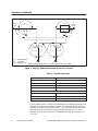
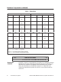
Table 2 Status Words
Status Words Indicating Dual RBCs
Status Words Indicating Dual Power Supplies
Word
Bit*
Base
Channel
Word
Bit**
Base
Channel
168
16
|
1
0
|
15
1
176
16
|
1
0
|
15
1
169
16
|
1
0
|
15
2
177
16
|
1
0
|
15
2
170
16
|
1
0
|
15
3
178
16
|
1
0
|
15
3
171
16
|
1
0
|
15
4
179
16
|
1
0
|
15
4
172
16
|
1
0
|
15
5
180
16
|
1
0
|
15
5
173
16
|
1
0
|
15
6
181
16
|
1
0
|
15
6
174
16
|
1
0
|
15
7
182
16
|
1
0
|
15
7
175
16
|
1
0
|
15
8
183
16
|
1
0
|
15
8
*Bit = 0: Dual RBCs present and good
Bit = 1: Error condition or single RBC
** Bit = 0: Dual power supply present and good
Bit = 1: Error condition or single power supply
Remote Base
Controller
6
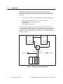
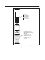
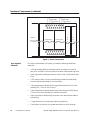
Each RBC (Figure 3) in the Redundant I/O system is an intelligent interface
between an RCC and a remote base containing either 8 or 16 I/O slots. The
dual RBCs are installed in an adapter chassis connected to the I/O base,
which can be located up to 15,000 feet from the PLC. If both RBCs are
installed and operational at power-up, the RBC on the right assumes the
active role.
Redundant I/O System
SIMATIC TI560/TI565 Redundant I/O System User Manual