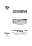
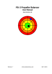
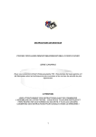
1
The Sole Manufacturer and Distributor in Czech Republic:
ATEC v.o.s.
Factory address: ATEC v.o.s., Opolanská 350, 289 07 Libice nad Cidlinou
Czech Republic
ATEC 321 FAETA
Flight and Operations Manual
Libice nad Cidlinou, March 2011
Flight and Operations Manual of ATEC 321 Faeta UL aircraft
ATEC v.o.s. Libice nad Cidlinou, Czech Republic
Page 1 of 53
Type of aircraft:
ATEC 321 FAETA
Serial number :
Registration/call sign:
LAA CR Type Certificate:
ULL-04 / 2005
Date of issue: 19.
10. 2005
The aircraft (Sport Flying Device) is not a subject of CAA authorisation and is to be operated at own
risk of the user.
The aircraft must be operated according to informations and limits listed in this manual.
Flight and Operations Manual of ATEC 321 Faeta UL aircraft
ATEC v.o.s. Libice nad Cidlinou, Czech Republic
Page 2 of 53
Contents
Chapter
General
1
Operational Limits
2
Emergency Procedures
3
Standard Procedures
4
Performances
5
Assembly, Disassembly
6
Aircraft Description and Systems
7
Maintenance
8
Weight, Centre of Gravity
9
Enclosures:
1. Log Book (example)
2. Records of Revisions
3. Service and Maintenance Book
Flight and Operations Manual of ATEC 321 Faeta UL aircraft
ATEC v.o.s. Libice nad Cidlinou, Czech Republic
Page 3 of 53
Chapter 1
1.
General
1.1.
1.2.
1.3.
1.4.
1.5.
1.6.
Introduction
Personal Data of the Owner
Aircraft Description
Modifications and Changes
Aircraft Technical Data
Three-View Sketch
Flight and Operations Manual of ATEC 321 Faeta UL aircraft
ATEC v.o.s. Libice nad Cidlinou, Czech Republic
Page 4 of 53
1.1.
Introduction
Information provided within this manual is a necessary requirement for an effective and save
operation of the ATEC 321 FAETA aircraft. The manual contents information which Manufacturer
considers as important.
1.2.
Personal Data of the Owner
Owner of aircraft:
Address:
Telephone No:
E-mail:
Date of ownership from:
to:
Owner of aircraft:
Address:
Telephone No:
E-mail:
Date of ownership from:
to:
Owner of aircraft:
Address:
Telephone No:
E-mail:
Date of ownership from:
to:
Flight and Operations Manual of ATEC 321 Faeta UL aircraft
ATEC v.o.s. Libice nad Cidlinou, Czech Republic
Page 5 of 53
1.3.
Aircraft Description
ATEC 321 FAETA is an ultralight, two-seater, cantilever, low-wing aircraft of all carbon composite
construction. The landing gear has a fixed tricycle gear with a steerable front wheel. The power unit
is of pulling configuration and consists of ROTAX 912 iS engine and of two-blade or three-blade fix or
ground adjustable FITI propeller.
1.4.
Modifications and Changes
If any structural or operational changes are made by the Manufacturer and need to be advised to the
owner, the related documentation will be delivered to you and you are obliged to record them into
your Manual. These documents will be published in ascending numerical series.
If the aircraft is sold to another person, the Manufacturer shell be announced about the name and
the address of the new owner.
1.5.
Aircraft Technical Data
Dimensions
Wing span
Length of fuselage
Total height
Wing area
Depth of mean aerodynamic chord
Span of horizontal tail surface
Flap position
I
II
III
Aileron deflection
up
down
Elevator deflection
up
down
Rudder deflection
L/R
9,6 m
6,2 m
2,0 m
10,1 m2
1,11 m
2,4 m
10 ° 45 mm
20 ° 90 mm
35 ° 150 mm
20 ° 90 mm
12 ° 55 mm
22 ° 80 mm
18 ° 65 mm
+-20° 180 mm
Wing profile
Root area
End area
SM 701
SM 701
Landing Gear (tricycle with frong wheel)
Wheel spacing
Wheel base
Tire dimensions
Tire pressure
1,9 m
1,4 m
350 x 120
0,16 MPa / 1,6 atp
Suspension
Main gear
Front wheel
composite springs
rubber suspension
Flight and Operations Manual of ATEC 321 Faeta UL aircraft
ATEC v.o.s. Libice nad Cidlinou, Czech Republic
Page 6 of 53
Brakes
hydraulic disc brakes on the main gear
Rescue System
USH 52 S SOFT PACK,
vMAX = 293 km/h
Weight
Empty weight
Maximum take-off weight
Maximum take-off weight including rescue system installed
Maximum luggage weight in the luggage compartment
kg
450 kg
472,5 kg
5 kg
Power Unit and Engine Parameters
Propeller producer
FITI desing s.r.o., Řevnice, Czech Republic
Type of propeller
FITI ECO COMPETITION 2 blade / 3 blade
Engine producer
BOMBARDIER – ROTAX GmbH, Austria
Engine type
ROTAX 912 iS SPORT
Engine Power
Take-off power
Maximum continuous power
Cruising power
Engine Speed
Maximum take-off engine speed
Max. continuous engine speed
Cruising engine speed
Engine idle speed
73,5 kW/100 HP/5800 RPM
72,0 kW/ 98 HP/5500 RPM
44,6 kW/ 60 HP/4800 RPM
5800 RPM / 5 minutes maximum
5500 RPM
4800 RPM
1400 RPM approximately
Water Temperature
Minimum
Maximum
50 °C
120 °C
Oil Temperature
Minimum
Maximum
Operational optimum
50 °C
130 °C
90 °C-110 °C
Oil Pressure
Maximum (short-term operated when cold start-up)
Minimum
Operational
Fuel Type
7,0 bar
0,8 bar (engine speed below 3500 RPM)
2,0 – 2,5 bar (over 3500 RPM)
Recommended motor unleaded petrol of minimum octane number RON 95, 97
Flight and Operations Manual of ATEC 321 Faeta UL aircraft
ATEC v.o.s. Libice nad Cidlinou, Czech Republic
Page 7 of 53
Oil Type
Any brand-name oil intended for 4 stroke motorcycle
containing gearbox additives - API SF, SG + GL4 or GL5.
AeroShell Sport Plus 4 10W-40 preferentially recommended.
Cooling Liquid
conventional (mix ratio 1:2)
engines,
ROTAX 912 iS is not a certified aviation engine. Any engine failure may occur at any time.
The pilot is fully responsible for the operation of this engine and accepts all risk and consequences
of an engine failure.
The correct operation of this aircraft is the sole responsibility of the pilot.
The pilot of a sport flying device is obliged to consider the flight altitude and flight track so that he
could be able to make safety landing in case of engine failure.
Flight and Operations Manual of ATEC 321 Faeta UL aircraft
ATEC v.o.s. Libice nad Cidlinou, Czech Republic
Page 8 of 53
1.6.
Three-View Sketch
Flight and Operations Manual of ATEC 321 Faeta UL aircraft
ATEC v.o.s. Libice nad Cidlinou, Czech Republic
Page 9 of 53
Chapter 2
2.
Operational Limits
2.1. Introduction
2.2. Air Speed
2.3. Weight
2.4. Centre of Gravity
2.5. Manoeuvre and Gust Envelope
2.6. Permitted Manoeuvres
2.7. Load Factors
2.8. Type of Operation
2.9. Crew
2.10. Fuel tank
2.11. Wind
2.12. Other Limitations
2.13. Labels and Markings
Flight and Operations Manual of ATEC 321 Faeta UL aircraft
ATEC v.o.s. Libice nad Cidlinou, Czech Republic
Page 10 of 53
2.1.
Introduction
The Chapter 2 contains operational limits necessary for safe operation of the aircraft.
2.2.
Air Speed (CAS)
Never exceed speed
vNE
270 km/h
146 kt
Do not exceed this speed in any case!
Design manoeuvre speed
vA
156 km/h
85 kt
After exceeding this speed, do not use full deflection of any control surfaces and do not make any
sudden control operations. An overload of the aircraft may occur!
Maximum design cruising speed
vC
230 km/h
123 kt
Do not exceed this speed except the flight in smooth air, but with caution!
Max. cruising speed at severe turbulence
vRA
224 km/h
122 kt
Do not exceed this speed at severe turbulence!
Max. speed, flaps deflected to I. (10 °)
Max. speed, flaps deflected to II. (20 °)
Max. speed, flaps deflected to III. (35 °)
Recommended speed, flaps deflected to III.
FE,I
FE,II
FE,III
VFE
130 km/h
120 km/h
110 km/h
90 km/h
70 kt
65 kt
59 kt
49 kt
Never exceed these speed limits when flaps deflected!
Stall speed, flaps retracted
vS1
64 km/h
35 kt
Flying this speed and with flaps retracted results in loss of lifting force and fall of the aircraft!
Stall speed in landing configuration
vSO
51 km/h
28 kt
Flying this speed with flaps deflected at the position III. results in loss of lifting force
and fall of the aircraft!
Flight and Operations Manual of ATEC 321 Faeta UL aircraft
ATEC v.o.s. Libice nad Cidlinou, Czech Republic
Page 11 of 53
2.3.
Weight
Empty weight
kg
Maximum take-off weight
450
Useful load
kg
kg
Never exceed the maximum take-off weight of the aircraft!
2.4.
Centre of Gravity ( CG )
CG of the empty aircraft
28,7
Flight range of CG
Flight and Operations Manual of ATEC 321 Faeta UL aircraft
ATEC v.o.s. Libice nad Cidlinou, Czech Republic
% MAC
27-36 % MAC
Page 12 of 53
2.5.
Manoeuvre and Gust Envelope (CAS)
vSO
vS1
vAF
vS1N
vF
vA
vG
vC
vH
vNE
vD
=
=
=
=
=
=
=
=
=
=
=
61 km/h
79,3 km/h
86,2 km/h
111,9 km/h
130 km/h
156 km/h
156 km/h
230 km/h
249 km/h
270 km/h
298,8 km/h
=
=
=
=
=
=
=
=
=
=
=
16,9 m/s
22,0 m/s
24 m/s
31,1 m/s
36,1 m/s
43,5 m/s
43,5 m/s
63,8 m/s
69,2 m/s
75,4 m/s
83 m/s
Flight and Operations Manual of ATEC 321 Faeta UL aircraft
ATEC v.o.s. Libice nad Cidlinou, Czech Republic
=
=
=
=
=
=
=
=
=
=
=
32,9 kt
42,8 kt
46,6 kt
60,5 kt
70,2 kt
84,6 kt
84,5 kt
124 kt
134 kt
146 kt
161,5 kt
Page 13 of 53
2.6.
Permitted Manoeuvres
Category of the aircraft:
Normal
Operations are limited to non-aerobatic manoeuvres that include:
-
Any manoeuvres necessary to normal flying
Training of stalls
Steep turns, in which the angle of bank is not more than 60°
Aerobatic manoeuvres are prohibited!
2.7.
Load Factors
Maximum positive load factor in CG
Maximum negative load factor in CG
2.8.
+ 5,1 G
- 3,1 G
Type of Operation
Only VFR day flights are permitted (flight by visual reference to the ground during the daytime)
IFR flights ( instrument flights ) and flights by ice formation are prohibited!
2.9.
Crew
Number of seats
Minimum weight of crew
Maximum weight of crew
2
60 kg
180 kg
2.10. Fuel tank
Fuel capacity
2 x 50 L
Not usable rest of fuel
1,2 L
Recommended motor unleaded petrol of minimum octane number RON 95, 97
2.11. Wind
The safe take-off and landing is only possible if the following wind speed limits are not exceeded:
a) take-off or landing against wind
up to 12 m/s
b) take-off or landing tail wind
up to 3 m/s
c) take-off or landing cross wind
up to 6 m/s
Never operate the aircraft exceeding wind range limits determined!
Flight and Operations Manual of ATEC 321 Faeta UL aircraft
ATEC v.o.s. Libice nad Cidlinou, Czech Republic
Page 14 of 53
2.12. Other Limitations
Smoking, using of mobile phone, explosives and combustible materials and movable objects
transportation are prohibited on board of the aircraft.
2.13. Labels and Markings
The aircraft shall be equipped with mandatory labels and markings. These must be placed on the
instrumental board in a visual field of pilot and must contain following information:
- Identification of the aircraft
• Identification label
• Serial number
• Designation
• Empty weight
• Maximum take-off weight
- Operating limits
• Weight limits depending on the weight of crew, fuel and luggage
• Speed limits for standard flight configurations
- Passenger Warnings
• Definition of aircraft category, its airworthiness conditions and limitations
• Intentional spins, stalls and aerobatics prohibition
Flight and Operations Manual of ATEC 321 Faeta UL aircraft
ATEC v.o.s. Libice nad Cidlinou, Czech Republic
Page 15 of 53
INTENTIONALLY LEFT
Flight and Operations Manual of ATEC 321 Faeta UL aircraft
ATEC v.o.s. Libice nad Cidlinou, Czech Republic
Page 16 of 53
Chapter 3
3.
Emergency Procedures
3.1.
3.2.
3.3.
3.4.
3.5.
3.6.
3.7.
3.8.
3.9.
Engine Failure on Take-off
Engine Failure in Flight
Rescue System Activation
Fire on Board
Engine Loss
Emergency Landing
Safety Landing
Aborted Landing
Vibrations
Flight and Operations Manual of ATEC 321 Faeta UL aircraft
ATEC v.o.s. Libice nad Cidlinou, Czech Republic
Page 17 of 53
3.1.
Engine Failure on Take-off
1.
Push the stick forward to get the aircraft to gliding flight maintaining the airspeed
of 100 km/h (54 kt).
Determine the wind direction, adjust flaps to appropriate position, close the fuel valve,
switch-off the ignition, adjust safety belts and switch off the main switch just before landing.
Note: Electric flaps actuation is only possible when the main switch is switched-on.
A) If up to 50m (160ft) of altitude, get the aircraft into the landing configuration and make a
landing in take-off direction with respect to eventual obstructions.
B) If higher than 50m (160ft) of altitude, choose a suitable area for emergency landing.
2.
3.2.
Engine Failure in Flight
1.
2.
3.
4.
Get the aircraft to gliding flight maintaining the airspeed of 100 km/h (54 kt).
Check the fuel level and make sure ignition is switched on.
If no significant engine or installation failure found, try to start up the engine again using
back-up fuel circuit.
If engine start-up is not possible, follow the instructions as described in Art. 3.1.
3.3.
Rescue System Activation
In case of distress, when definitely losing control of flight, activate the rescue system.
Switch off the ignition
1.
2.
Adjust safety belts
3.
Activate the rescue system
In case of landing on a limited area, when collision with an obstacle is inevitable, use the rescue
system as a braking device of the aircraft.
The aircraft can be damaged or the crew may be injured when using a rescue system!
3.4.
Fire on Board
1.
2.
3.
4.
5.
Close the fuel valve
Open the throttle
Switch-off the main switch and ignition
Make emergency landing
Get off the aircraft
3.5.
Engine Loss
1.
2.
3.
Speed
100 km/h (54 kt)
Flaps retracted
Instruments within tolerated values
Flight and Operations Manual of ATEC 321 Faeta UL aircraft
ATEC v.o.s. Libice nad Cidlinou, Czech Republic
Page 18 of 53
3.6.
Emergency Landing
Carried out in case of engine failure:
1.
2.
3.
4.
5.
6.
7.
Speed
100 km/h (54 kt)
Adjust safety belts
Flaps according to situation
Report the situation by the radio
Close the fuel valve
Turn off the ignition
Turn off the main switch
In case of emergency landing on terrain, on areas which are not authorized to take-off/landing of
sport flying devices, the aircraft can be damaged or the crew may be injured!
3.7.
Safety Landing
Carried out in case of orientation loss, fuel exhaustion or another reason when the aircraft is fully
controllable.
4.
5.
6.
Determine the wind direction
Choose a suitable landing area
Make a low pass into the wind along the right-hand side of landing area and inspect the
terrain thoroughly.
Make a pattern flight
Calculate the landing plan
Land in the first third of the landing area using flaps landing position
3.8.
Aborted Landing
1.
2.
3.
Carried out in case of wrong calculation of landing manoeuvre or bounce when landing and the pilot
considers aborted landing manoeuvre as more safety and decides to continue the flight.
1.
2.
3.
4.
5.
Set up engine speed on maximum power
Set up take-off flaps position – I
Get to level speed of 110 km/h (59 kt)
Draw up control stick slowly to get aircraft into climbing by speed 110 – 120 km/h (59 – 65 kt)
Retract flaps
Throughout the flight, maintain the aircraft in take-off trajectory using rudder control.
3.9.
Vibrations
In case of unusual vibrations occur, it is necessary to:
1.
2.
Set the engine speed to appropriate run on which the vibrations are the lowest
Carry out the safety landing, eventually find the nearest aerodrome to land
Flight and Operations Manual of ATEC 321 Faeta UL aircraft
ATEC v.o.s. Libice nad Cidlinou, Czech Republic
Page 19 of 53
INTENTIONALLY LEFT
Flight and Operations Manual of ATEC 321 Faeta UL aircraft
ATEC v.o.s. Libice nad Cidlinou, Czech Republic
Page 20 of 53
Chapter 4
4.
Standard Procedures
4.1. Pre-Flight Inspection
4.1.1. Procedures Before Entering the Cockpit
4.1.2. Procedures After Entering the Cockpit
4.1.3. Procedures Before Engine Start-up; Engine Start-up
4.2.
4.3.
4.4.
4.5.
4.6.
4.7.
Engine Warm-up
Taxiing
Engine Check
Procedures Before Take-off
Take-off and Climbing
Cruising Flight
4.7.1. Autopilot
4.8. Descending and Landing
4.9. Flight in Rainy Conditions
Flight and Operations Manual of ATEC 321 Faeta UL aircraft
ATEC v.o.s. Libice nad Cidlinou, Czech Republic
Page 21 of 53
4.1.
Pre-Flight Inspection
It is important to carry out the appropriate pre-flight inspection. To perform a negligent or
incomplete inspection could be the cause of an accident. The Manufacturer recommends to do the
following procedure:
4.1.1. Procedures Before Entering the Cockpit
1.
2.
3.
4.
5.
6.
7.
8.
Ignition
switched off
Main switch
switched off
Wings
check surfaces condition, ailerons and flaps free movement, clearances,
hinges and connections of the controls, security of wing pins, Pitot tube
Tail surfaces
check surface condition, elevator and rudder secure connections, clearances
and free movement
Fuselage
check surface condition
Landing gear
check laminate spring surface condition, secure fixation of main and front
wheels and their covers, screws and nuts security, correct tire pressure, brake function
Engine
check condition and fastening of engine cowlings, the condition of engine
bed, intact fuel, oil and cooling system hoses, screws and nuts security, exhaust pipe and
carburettor attachment, cooling liquid and oil level, fuel system drain
Propeller
check surface condition, intact, condition and fastening of the propeller
cone
4.1.2. Procedures After Entering the Cockpit
1.
Cockpit
check fastening and locking of the canopy, correct function and
condition of electrical installation of instruments, condition of flight instruments, fuel level
check, proper function of controls
check function
2. Foot-operated steering
3. Brakes
check function, brakes on
4. Hand–operated steering
check function
5. Flaps
check function, retract
6. Fuel valve
turned off
7. Engine controls
switched off, throttle idle
8. Fuel level indicator
check fuel volume
9. Main switch
switched off
10. Ignition
switched off
11. Instruments
check condition, zero values, altimeter adjustment
4.1.3. Procedures Before Engine Start-up, Engine Start-up
1.
2.
3.
4.
5.
6.
7.
Rescue system
unlock
Safety belts
fasten
Canopy
close and lock
Parking brake
on
Fuel valve
turn on
(open/select the left or right position depending your needs for the appropriate tank use)
Electric fuel pump
on
Throttle
idle
Flight and Operations Manual of ATEC 321 Faeta UL aircraft
ATEC v.o.s. Libice nad Cidlinou, Czech Republic
Page 22 of 53
8.
9.
10.
11.
12.
13.
14.
15.
16.
17.
18.
19.
20.
Main switch
switch on
Propeller
in “take off” position (in case of flight adjustable propeller)
EMS
switch on, wait for the display activation
LANE switch circuit A
turn on
LANE switch circuit B
turn on
EMS lights
see engine user manual
Backup battery switch
turn off
Start power switch
turn on
Starter button
push, untill the engine runs
Start power switch
turn off
Backup battery switch
turn on
Increase RPM to cca 2000/min
Oil pressure check
must be in operation range in 10 seconds, continue in RPM
increase by 3 bar
21. Continue in warm-up engine according to article 4.2
Never unlock neither open the canopy after the engine start-up!
4.2.
Engine Warm up
Start to warm up the engine when 2000 RPM, hold approx. 2 minutes and then continue up to 2500
RPM until the oil temperature reaches 50oC. Start taxiing right after engine’s warm-up to the
operation temperature, to prevent unsufficient cooling of the engine by staying at the place.
4.3.
Taxiing
Recommended maximum speed of taxiing is 15km/h (8kt). The direction is controlled by the front
wheel. Braking is carried out with the brake lever on the left stick. Control stick is on the neutral
position.
- in case of strong headwind, push the control stick forward
- in case of crosswind, keep the control stick position opposite to wind direction
4.4.
1.
2.
3.
4.
5.
6.
Engine Check
Brakes
Engine throttle
Switch off 1st ignition circuit
on
engine speed of 4000 RPM
engine speed after stabilizing must not drop bellow
300 RPM
Switch on both ignition circuits
engine speed of 4000 RPM
nd
Switch off 2 ignition circuit
engine speed after stabilizing must not drop bellow
300 RPM
Note: The RPM speed difference between ignition circuits running separately must not be more
than 120 RPM.
Left and Right fuel tank check
during engine run, the fuel pressure must not drop bellow
the allowed value in either of fuel tanks in use. During the change-over of fuel tank, a shortterm pressure drop may occur, but after the tank is selected, the pressure must increase back to
appropriate values.
Flight and Operations Manual of ATEC 321 Faeta UL aircraft
ATEC v.o.s. Libice nad Cidlinou, Czech Republic
Page 23 of 53
4.5.
Procedures Before Take-off
1.
2.
3.
4.
5.
Brakes
brake-on
Foot-operated steering
free travel
Hand-operated steering
free travel
Flaps
position I.
Fuel valve
open/select the appropriate (left/right) position on the selector
depending on fuel tank intended to use.
Note: The left fuel tank is considered as the main one, where the return circuit is installed so the
fuel flows back only into this tank. If the left tank is filled up, select first the left tank and then
the right one. The fuel can only return to the left tank.
6. Throttle
idle
7. Fuel gauge indicator
fuel volume check
in “take off” position (in case of flight adjustable propeller)
8. Propeller
9. Instruments
on and within operating limits
10. Safety belts
adjusted, secured
11. Canopy
closed and locked
4.6.
Take-off and Climbing
Release the brakes. Make the aircraft move by accelerating until the maximum throttle position is
reached. Control stick is in neutral position. Control the front wheel and the rudder as to keep the
aircraft in the runway trajectory. When reaching the speed of 75km/h (45kt), lift up the aircraft of
the ground and continue the take-off up to the speed of 110 km/h (59kt). Then, gently pull the
control stick to start climbing when optimum speed of 110km/h (59kt). After reaching the stable
climbing speed of 110-120km/h (59-65kt) and over 50m (160ft) of altitude, retract the flaps fluently.
During the take-off, the engine operating limits must not be exceeded. After reaching the flight level,
adjust the propeller into “cruise” position (in case of flight adjustable propeller).
4.7.
Cruising Flight
ATEC 321 FAETA has good flight characteristics in the whole range of permitted speeds and centre of
gravity positions. The cruising speed range is of 120 – 227km/h (65 – 122kt).
4.7.1 Integra Autopilot (optional)
The Autopilot (AP) is two-axis device controlled by EFIS TL-6524 Integra. If the AP is not active, the
electromagnetic connector of servo units is disconnected and the AP installation does not influence
the steering system of the aircraft. The AP system is intended to keep requested track and altitude.
Activate the AP after the take-off when reaching minimum 1000 ft altitude.
For landing deactivate the AP before entering aerodrome traffic circuit.
Flight and Operations Manual of ATEC 321 Faeta UL aircraft
ATEC v.o.s. Libice nad Cidlinou, Czech Republic
Page 24 of 53
AP activation instructions:
1. Balance the aircraft into horizontal direct flight by trimming.
2. Push the AP button on Integra.
3. To select the type of controlled axis, push the appropriate button:
- BOTH
- ROLL
- PITCH
4. Select requested flight mode:
- STABILIZATION – the aircraft will continue the same tracking and altitude since the moment
of the AP activation
- BUGS – the aircraft will continue the tracking and altitude adjusted with BUGS. The tracking and
altitude bugs are adjusted by the left button on Integra
- NAV – the aircraft will follow the track adjusted on GPS and will keep the same altitude since the
moment of AP activation. The altitude is possible to change by adjusting the bug by the left button
on Integra. For the flight in NAV mode, it is needed, that GPS communicate with Integra and the
tracking is active. When reaching the destination point, the aircraft begins circling around such area.
After the required flight mode is adjusted, the AP is activated and the AP ON sign on Integra screen is
switched on. The aircraft continues the flight according to selected flight mode.
Keep the engine RPM speed according to appropriate flight mode!
The AP is adjusted for minimum and maximum speed limits. If the aircraft speed is getting close to
limit values, you will be announced by warning message requesting you to adjust the engine
performance. If you do not follow the warning request, the AP will stop keeping adjusted altitude
and start to keep the aircraft within the speed limits by descending or climbing.
AP deactivation:
Hold the control stick before the AP deactivation.
Deactivate the AP either by pressing the AP FN button, then AP OFF button on Integra or by pressing
deactivating button installed on the control stick. The AP ON sign on Integra screen will switch off.
Note: The general user set up of the AP functions is available in AUTOPILOT SETUP menu.
For more information check the Integra´s appropriate manual.
4.8.
Descending and Landing
Descending
Carry out the descending with the throttle on idle run at the speed of 100km/h (54kt).
Flaps position limits according to Art. 2.2. Propeller into “take off” position.
Procedures on final:
1. Propeller into “take off” position (in case of flight adjustable propeller)
2. Speed of 90km/h (49kt)
3. Flaps position III (position II in case of strong turbulence or strong headwind)
4. Throttle idle or corrected if necessary
5. Instruments within the permitted limits
Flight and Operations Manual of ATEC 321 Faeta UL aircraft
ATEC v.o.s. Libice nad Cidlinou, Czech Republic
Page 25 of 53
Landing
The speed of the aircraft in the hold-up position decreases by soft pulling the control stick until
touching down at the speed of 70km/h (38kt). After the touch down of the front wheel, the landing
distance can be shortened by braking.
Do not apply a maximum braking effect except an extreme situation. A frequent brake use results
in undue wear of tyres, brake pads and discs. A frequent intensive braking may cause a mechanical
over-stress of undercarriage and other load bearing structure. This may shorten the life-time of
the airframe.
4.9.
Flight in Rainy Conditions
During the flight in the rain, it is necessary to pay close attention to the aircraft control because of
poor visibility and canopy limited transparency. Furthermore, shorter hold-up position when landing
and extended take-off distance must be taken into account.
Maintain the following speeds during the flight in the rain:
1.
2.
3.
Climbing
Cruising flight
Descending to land
120 km/h (65kt)
120 – 180 km/h (65 – 97kt)
110 km/h (59kt), flaps positions I and II as by Art. 2.2.
Flight and Operations Manual of ATEC 321 Faeta UL aircraft
ATEC v.o.s. Libice nad Cidlinou, Czech Republic
Page 26 of 53
Chapter 5
5.
Performances
5.1.
5.2.
5.3.
5.4.
5.5.
5.6.
5.7.
5.8.
Introduction
Air Speed Indicator Corrections
Stall Speed
Altitude Loss by Stalling
Take-off Distance up to 15m / 50ft of Altitude
Rate of Climb
Cruising Speeds
Flight Range
Flight and Operations Manual of ATEC 321 Faeta UL aircraft
ATEC v.o.s. Libice nad Cidlinou, Czech Republic
Page 27 of 53
5.1.
Introduction
The Chapter contents the information on speed indicator corrections, stalling speed and other
performances of the ATEC 321 FAETA with ROTAX 912 iS engine and propeller FITI ECO
COMPETITION 3L/158 adjusted to the angle of attack.
5.2.
Air Speed Indicator Corrections
CAS km/h
57,0
69,0
80,0
100,0
110,0
120,0
130,0
140,0
158,0
170,0
180,0
200,0
212,0
220,0
240,0
249,0
260,0
270,0
280,0
300,0
5.3.
CAS kt
30,8
37,3
43,2
54,0
59,4
64,8
70,2
75,6
85,3
91,8
97,2
108,0
114,5
118,8
129,6
134,4
140,4
145,8
151,2
162,0
IAS km/h
51,2
64,0
75,8
97,2
108,8
120,4
132,0
143,7
164,6
178,5
190,1
213,4
227,3
236,6
259,9
270,3
283,1
294,7
306,4
329,6
IAS kt
27,6
34,6
40,9
52,5
58,7
65,0
71,3
77,6
88,9
96,4
102,7
115,2
122,8
127,8
140,3
146,0
152,9
159,2
165,4
178,0
Deviation km/h
-5,8
-5,0
-4,2
-2,8
-1,2
0,4
2,0
3,7
6,6
8,5
10,1
13,4
15,3
16,6
19,9
21,3
23,1
24,7
26,4
29,6
Deviation kt
-3,1
-2,7
-2,3
-1,5
-0,7
0,2
1,1
2,0
3,6
4,6
5,5
7,2
8,3
9,0
10,7
11,5
12,5
13,4
14,2
16,0
Note
vS0
vS1
vFIII
vFII
vFI
vA
vRA
vC
vH
vNE
vD
Stall Speed (CAS)
Engine idle
Solo flight
472,5 kg
Engine off
Solo flight
472,5 kg
Flaps retracted
70,5 km/h
38,1 kt
64,0 km/h
34,6 kt
Flaps I (10°)
61,9 km/h
33,4 kt
62,0 km/h
33,5 kt
Flaps II (20°)
58,7 km/h
31,7 kt
60,8 km/h
32,8 kt
Flaps III (35°)
47,1 km/h
25,4 kt
51,2 km/h
27,6 kt
Flaps retracted
70,5 km/h
38,1 kt
64,0 km/h
34,6 kt
Flaps I (10°)
61,9 km/h
33,4 kt
62,0 km/h
33,5 kt
Flaps II (20°)
58,7 km/h
31,7 kt
60,8 km/h
32,8 kt
Flaps III (35°)
47,1 km/h
25,4 kt
51,2 km/h
27,6 kt
Flight and Operations Manual of ATEC 321 Faeta UL aircraft
ATEC v.o.s. Libice nad Cidlinou, Czech Republic
Page 28 of 53
5.4.
Altitude Loss by Stalling
Level flight flap position
I
II
III
0
5.5.
Rotax 912 iS
Take-off distance
245 m
800 ft
265 m
870 ft
Rate of Climb - when speed of 110 km/h (59 kt)
engine
Solo flight
472,5 kg
5.7.
Altitude loss
30 m
100 ft
30 m
100 ft
30 m
100 ft
30 m
100 ft
Take-off Distance up to 15m / 50ft of Altitude
engine
Runway surface
Asphalt
Grass
5.6.
Flap deflection
10°
20°
35°
0
Rotax 912 iS
7,5 m/s 24,60 ft/s
6,0 m/s 19,70 ft/s
Cruising Speeds
ROTAX 912 iS
Speedu
km/h
kt
120
65
140
76
160
86
180
97
200
108
220
119
240
130
RPM
1/min
3350
3700
4050
4330
4700
5100
5500
TP
52%
62%
69%
73%
86%
92%
98%
Flight and Operations Manual of ATEC 321 Faeta UL aircraft
ATEC v.o.s. Libice nad Cidlinou, Czech Republic
Fuel consumption
l/h
5,4
7,0
8,0
9,4
12,1
14,7
18,4
Page 29 of 53
5.8.
Flight Range
When maximum fuel capacity of 100 l
ROTAX 912 iS
Speed
km/h
140
160
180
200
220
240
kt
76
86
97
108
119
130
Range of flight
km
n.m.
1930
1043
1920
1038
1824
986
1553
840
1385
749
1184
640
Flight endurance
h
13h 47 min
12h 0 min
10h 8min
7h 46 min
6h 18min
4h 55 min
Fuel reserve 30 min
l
3,5
4
4,7
6
7,4
9,2
Information on engine RPM, consumption, flight endurance and flight range are of informative
character only. These values depend on propeller type and adjustment, flight altitude, temperature,
air pressure and loading. The flight range is considered as theoretic, when windless conditions.
Consider these factors when planning your flight and figure on the safety flight reserve.
Flight and Operations Manual of ATEC 321 Faeta UL aircraft
ATEC v.o.s. Libice nad Cidlinou, Czech Republic
Page 30 of 53
Chapter 6
6.
Aircraft Assembly/Disassembly
6.1. Introduction
6.2. Horizontal Tail Assembly/Disassembly
6.3. Wings Assembly/Disassembly
Flight and Operations Manual of ATEC 321 Faeta UL aircraft
ATEC v.o.s. Libice nad Cidlinou, Czech Republic
Page 31 of 53
6.1.
Introduction
The assembly of individual parts of the aircraft is described in this chapter. At least two persons are
needed for assembly/disassembly. All parts necessary for assembly are delivered with the aircraft.
Before assembly, clean, grease and then secure all pins. Pay attention to correct adjustment of
ailerons and flaps, which is carried out by shortening and prolonging of connecting pushrods.
During each next assembly, it is necessary to replace locking nuts and split pins with new pieces.
After aircraft assembly, carry out deflections adjustment by levelling record and engine run test with
a focus on both fuel tanks function and check fuel indicators correct function.
6.2.
Horizontal Tail (HT) Assembly / Disassembly
At least two persons are needed for HT assembly/disassembly. Third person is recommended to
push the fuselage tail down to the ground for better access to HT.
Pay attention during the manipulation - avoid a fall of small parts into the tail fin inner space during
manipulation!
Horizontal tail assembly
•Elevator pushrod connection
Deflect the control stick into the „pushed“ position and secure softly (for better accessibility of
elevator pushrod).
Put the elevator on the appropriate place on the fuselage tail over the rudder. Your assistant holds
the horizontal tail in upward position (for better access to pushrod) over the rudder, keeping
stabilizer deflected maximally in „up“ position. Connect the pushrod with the elevator by the pin of
Ø5mm and spacer + split pin. Connect the cable connector of servo (if electrical trim option).
•Fixing the horizontal tail to the fuselage
Put the horizontal tail on the fuselage and fix it with two M8 main fitting screws. Do not fully tighten
it yet.
Insert the vertical screw M6 (with nylon) into the hole on the upper side of horizontal tail and
tighten it fully with adequate power.
Come back to both M8 main fitting screws and tighten them fully.
•Securing the screws
Secure these both screws M8 with a wire. Appropriate holes are situated in the main fittings and
four holes are in the screw head.
Secure the vertical nylon-screw also with wire. One hole is drilled in the horizontal tail body and two
holes in the screw head.
Finally, cover this hole with white sticker (to avoid water inlet).
Flight and Operations Manual of ATEC 321 Faeta UL aircraft
ATEC v.o.s. Libice nad Cidlinou, Czech Republic
Page 32 of 53
•HT fittings covers assembly.
HT fittings covers help to avoid vibration occurence in flight. Apply the HT fittings fiber-glass covers
(obtained with double-side tape) according to following picture:
Horizontal tail disassembly
Put away the fiber-glass covers of HT fittings (pay attention to not to dammage it - needed for next
assembly). Release and unscrew M6 screw, which adjusting the position of HT and is situated on the
upper side of stabilizer. Release and remove M8 screws of the main HT fittings. Tilt the HT so that it
is possible to disconnect the pin of HT control. Remove the HT and put it into a safe place to prevent
its damage. Secure the ball bearing with a binding wire.
6.3.
Wings Assembly/Disassembly
At least two persons are needed for wings assembly/disassembly.
Do not push on the wing surface during manipulation to avoid cracks on the gel-coat (especially in
the area of material connections). Lay wings on a smooth, soft pad (e.g.mattress).
Wings assembly
(valid for the left as for the right wing)
•Flap pushrod preparation - connection in wings
Put the wing by its leading edge down on the soft pad. Hold the wing with your assistant, who
deflect the flap to enable a better access to you. Connect the flap pushrod with the flap lever
installed inside the wing. Pay attention to install the correct pushrod (LEFT or RIGHT) to appropriate
wing. Pay attention to correct pushrod position (non-adjustable end leads into the wing and the
adjustable one into the fuselage - see the sticker with letters L/R on its upper side). Fix the
connection with the pin Ø5mm and spacer + split pin (all parts attached to the pushrod).
•Aileron pushrod preparation - connection in wings
Screw the aileron pushrod to the adjustable end which extrudes from the wing. Pay attention to
install the correct pushrod (LEFT or RIGHT) to appropriate aileron. Exact tuning will be adjusted later.
•Wing Connection to the fuselage
Prepare two of main wing pins lubricating them with an adequate quantity of vaseline. Pay attention
- UPPER wing pin is WITHOUT scroll, LOWER wing pin is WITH scroll.
Your assistant holds the wing at the wingtip and you at the root (the third assistant which can hold
the wing at the root’s trailing edge is useful, but not necessary).
Flight and Operations Manual of ATEC 321 Faeta UL aircraft
ATEC v.o.s. Libice nad Cidlinou, Czech Republic
Page 33 of 53
Insert the wing into the fuselage partially that those two pushrods (aileron and flap) enter the
fuselage through corresponding holes. Support the wing by your knees and connect the rest of
equipment:
- static and dynamic pressure hoses of Pitot tube (just on the left wing)
Note: Pay attention not to interchange the hoses of Pitot tube during assembly.
- quick coupling of fuel hoses from fuel tanks
- connector of fuel gauges cable
- connector of strobes/position lights cable (if equipped with)
Finish inserting of the wing into the fuselage and apply the main pins. Start with upper pin (without
scroll) and then the bottom pin (with scroll). This operation requires careful using of the hammer
through the metal rod (Ø 18mm). The assistant at the wing tip pays attention to the correct dihedral
angle. Both pins must be inserted to their fully beaten position.
Secure the pins with the bolt from upper side – tightening moment is approx. 25 Nm.
Apply the locking nut M10 from the bottom side, then the wing connection is secured completely.
Finally, cover the holes with white sticker (to avoid water inlet).
•Flaps pushrods connection in the cockpit
Take the seats out of the cockpit – as to be the flap lever in the central tunnel accessible.
Realize the connection with the pin Ø5 and spacer + split pin (all parts attached to the pushrod).
There is a permitted exception – to insert the pin Ø5 from the bottom side (for better accessibility by
assembling the spacer and split pin)
Install seats back.
•Aileron pushrods connection in the cockpit
Screw the pushrod (to the control stick) into the fully tightened position and then loosen it up in a
number of turns (marked on the pushrod). This ensures correct neutral position of ailerons. Realize
the connection with the pin Ø5 and spacer + split pin (all parts attached to the pushrod)
Wings disconnection
First of all, drain off the fuel from both wing tanks.
Disconnect the rods of ailerons (on the control stick) and flaps rods (in the central tunnel) in the
cockpit.
Release and remove the locking nut of the bolts of the wing pins. Screw the bolt off by approx. 2cm.
The assistant, holding it at the wing tip, can lift the wing a little. Using hammer, knock out the
bottom pin by light taps on the head of the bolt. Unscrew the bolt and remove the bottom pin. Then
the upper pin is driven out using the hammer through the metal rod of Ø 18mm.
After pins removal, support the wing by your knees and disconnect the equipment:
- static and dynamic pressure hoses of Pitot tube (just on the left wing)
Note: Pay attention not to interchange the hoses of Pitot tube during their re-assembly.
- quick coupling of fuel hoses from fuel tanks
- fuel gauges cable and strobes/position lights cable (if equipped with)
Flight and Operations Manual of ATEC 321 Faeta UL aircraft
ATEC v.o.s. Libice nad Cidlinou, Czech Republic
Page 34 of 53
Chapter 7
7.
Aircraft and System Description
7.1.
7.2.
7.3.
7.4.
7.5.
7.6.
7.7.
7.8.
7.9.
7.10.
7.11.
Wing
Fuselage
Tail Surface
Landing Gear
Steering
Drive Unit
Fuel System
Instruments
Controlling Elements
Canopy
Cockpit Equipment
Flight and Operations Manual of ATEC 321 Faeta UL aircraft
ATEC v.o.s. Libice nad Cidlinou, Czech Republic
Page 35 of 53
7.1.
Wing
The cantilever tapered backswept wing of an angle of 5,5° with SM 701 airfoil along the all span is a
reinforced shell of a carbon-fibre sandwich with a carbon-fibre coating. The wing spar is made of
laminated hard beech wood saturated with synthetic resin and is situated in 30% of wing depth. The
ailerons are hinged on the rear spar and slotted flaps are hinged on fiberglass hinges. Ailerons and
flaps are made of all composite structure. Wing root ribs are made of carbon sandwich, other ribs
are of plastic foam. The main spar is welded of high quality CrMo steel tubes.
7.2.
Fuselage
The fuselage is all composite carbon-fibre shell braced with carbon sandwich bulkheads, NOMEX
honeycomb and hardened foam. The fuselage cross section is of elliptic shape with a spacious
cockpit and aerodynamic wing bases. In the front part of the fuselage is the engine separated from
the cockpit by fireproof wall to which the engine mount and the steerable nosewheel are fixed. The
cockpit is covered with the canopy. The luggage compartment with two small side-windows behind
seats are the part of the cockpit.
7.3.
Tail Surface
The T-shaped tail surface construction consists of tapered vertical and horizontal tail with fix
stabilizer and elevator. The elevator trim can be mechanical or electrical. The tail fin is an integral
part of fuselage. The rudder suspended to the last fuselage bulkhead is made of fiber-glass.
7.4.
The Landing Gear
The landing gear is a fixed tricycle undercarriage with a steerable front wheel. main gear is
constructed as a pair of leaf springs of composites. The front leg is made of composites and metal
tube suspended with rubber spring. The main gear is a pair of composite springs. Electronic main
wheels size is 350x120 mm, front wheel size is 300x100 mm. The main wheels are equipped with
hydraulic disc brakes. Fairings are installed on all wheels.
7.5.
Steering
The steering of all control surfaces is duplicated. The ailerons, flaps and elevator are controlled by
control rods and levers, the rudder is controlled by steel wire ropes. Lift flaps are optionally
equipped with electrical control. All control attachments are situated as to not interfere with the
airframe contour. The important checking points in wings are equipped with inspection holes with
perspex covers.
7.6. Drive Unit
The standard option of the drive unit is ROTAX 912 iS engine and three or two blade FITI ECO
COMPETITION propeller, which can be fix, ground adjustable or adjustable in flight.
Flight and Operations Manual of ATEC 321 Faeta UL aircraft
ATEC v.o.s. Libice nad Cidlinou, Czech Republic
Page 36 of 53
7.7.
Fuel System
The fuel system consists of two fuel tanks inbuilt in wings with a total fuel capacity of up to 100 litres
(2 x max.50l). The piping connection is equipped with a sediment bowl and a drain plug. The fuel
supply is assured by two independent circuits with back-up electrical pump. The fuel pressure is
monitored by fuel-pressure gauge. When the fuel indicator light is turned-on, the fuel reserve is 7L.
7.8.
Instruments
The instrumental equipment consists of basic instruments for flight and engine control and
navigation. The static and dynamic pressure is taken from the Pitot tube installed at the bottom of
the left wing. Instruments layout on the dashboard is described on the picture in Art. 7.11.
If the aircraft is equipped with SSR transponder, this must be active during the flight. The installation
of SSR transponder must be provided by competent authorized person.
Basic transponder squawks: 2000 7000 7500 7600 7700 -
controlled flight
uncontrolled flight
unlawful interference (hijack)
communication failure / radio contact loss
emergency
When setting up the new squawk the transponder must be in “STAND-BY” mode.
7.9.
Controlling Elements
Foot-operated control
Pushing the left pedal when adequate speed, the aircraft turns left when moving on the ground or in
the air, and vice versa. Pedals can be adjustable in three positions (optional equipment).
Hand-operated control
By pulling the control stick towards the pilot, the nose lifts up (the angle of attack increases) and the
aircraft climbs. By pushing the control stick, the aircraft descends. By deflecting the control stick to
left, the aircraft banks to left, and vice versa.
Wing flaps – mechanical option
By pressing the securing pin on the flaps control lever, wing flaps are released and ready to actuate.
Pulling the lever upward flaps are extending step by step to positions I, II, III, and vice versa.
Wing flaps – electric option
The flaps are actuated by linear potentiometer adjusting positions OFF, I, II, III. All flap positions are
indicated by indicator light.
Engine throttle
By moving the throttle forward, the engine power increases, and vice versa.
Choke
Choke pushrod pulled – choke is turned on
Choke pushrod pushed – choke is turned off
Flight and Operations Manual of ATEC 321 Faeta UL aircraft
ATEC v.o.s. Libice nad Cidlinou, Czech Republic
Page 37 of 53
7.10. Canopy
The cockpit is covered with hinged perspex canopy with two small sliding windows. The canopy is
opening up and backward. Electrical blocking system on canopy lock disables to start-up the engine if
the canopy is not closed well. Mechanical blocking system (the lever to open/close canopy) prevents
from canopy self-opening during the flight. Small fan installed upside the dashboard avoids canopy
fogging (optional equipment).
7.11. Cockpit Equipment
(picture and description of concrete cockpit)
Flight and Operations Manual of ATEC 321 Faeta UL aircraft
ATEC v.o.s. Libice nad Cidlinou, Czech Republic
Page 38 of 53
Chapter 8
8.
Care and Maintenance
8.1.
8.2.
8.3.
8.4.
8.5.
Maintenance Schedule
Aircraft Repairs
Engine Major Overhaul
Anchorage of the Aircraft
Cleaning and Care
Flight and Operations Manual of ATEC 321 Faeta UL aircraft
ATEC v.o.s. Libice nad Cidlinou, Czech Republic
Page 39 of 53
8.1.
Maintenance Schedule
Inspection, Mandatory Work
Engine
As per ROTAX Manual attached.
Engine Compartment
Engine Bed
Check integrity of construction with a special focus on welds, fixing
points, silent blocks, bushings. Check surface condition.
Bolted Connections
Check surface condition of bolted connections, bearing surfaces. Check
securing and tightening. Tighten and re-secure if necessary. Replace
locking nuts, split pins and securing wires.
Silentblocks
Check elasticity of engine bearing, integrity of rubber blocks, degree of
permanent deformation. Replace silent blocks if necessary, tighten,
secure.
Oil, Water and Fuel Hoses
Check surface integrity, liquid leak proofness, condition of connections,
protection avoiding touch with oscillating parts and exhaust system.
Replace if necessary.
Working Liquids
Check level, refill according to instructions of engine producer.
Coolers
Check integrity, sealing, purity.
Controls
Check control forces, free play, hinges, end stops adjustment, selflocking. Adjust, secure.
Exhaust piping
Check integrity, sealing, surface condition, corrosion degree, springs
condition and springs prestress. Grease ball connections with a special
lubricant.
Carburettors
Check surface condition, controls adjustment, condition of elastic
connection flange – integrity, sealing. Replace flange if material
degradations or surface cracks appear.
Electric Installations
Check condition, integrity and purity of cables, insulation, contacts,
welds, bunched cables attachments to airframe and bushings. Check
gauges and senders connections.
Propeller Attachment
Check condition of bolts, tightening moments, securing.
Flight and Operations Manual of ATEC 321 Faeta UL aircraft
ATEC v.o.s. Libice nad Cidlinou, Czech Republic
Inspection Period
(hours)
10 25 50 100 200
x
x
x
x
x
x
x
x
x
x
x
Page 40 of 53
10 25 50 100 200
Cockpit
Control Sticks
Check free movement in longitudinal and cross direction, clearance fits,
end stops adjustment, securing. Replace pins or bolts if worn-out,
grease, secure.
Rudder Control
Check integrity of pedals with a special focus on surface cracks near
welds. Full and free movement right and left (raise nose wheel off
ground), end stops adjustment, rudder cables tension, clearance fits,
securing. Adjust, replace worn-out parts, grease, secure.
Flap Control
Check free movement of flaps and control lever, stable bearing in each
flap position, interlock pin wear. Replace worn-out parts, grease, secure.
Canopy – Open / Close
Check condition and function of locks and hinges, canopy bearing.
Adjust, replace worn-out parts, grease, secure.
Flight and Engine Instruments
Check legibility, markings, mounting in the panel board, air-operated
and electric installation, wiring.
Electric Installations
Check condition, integrity and purity of cables, insulations, contacts and
welds. Battery attachment, operating condition.
Safety Belts
Check fixing points rigidity, belt surface condition, adjustment.
Fuel System
Check leak proofness, fuel supply, pumps, gauge and valve function,
tank ventilation and deterioration. Replace fuel filters.
Parachute Rescue System
Visual check of general condition, rocket, lines, attachment to bulkhead.
Maintenance as by instructions of rescue system producer.
Landing Gear
Main Gear
Check attachment rigidity, surface condition, clearance, degree of
permanent deformation.
Wheels
Check attachment, brakes condition, brake pads and disc condition,
braking system leak proofness. Attachment and purity of wheel spats.
Front Gear
Check general condition, surface, integrity, rubber spring condition and
deflection when loaded, steering condition. Grease sliding bearings,
replace rubber springs if worn-out.
Fuselage
Check general condition, integrity, purity. Antennas, lights, covers and
cowlings attachment.
Flight and Operations Manual of ATEC 321 Faeta UL aircraft
ATEC v.o.s. Libice nad Cidlinou, Czech Republic
x
x
x
x
x
x
x
x
x
x
x
x
x
Page 41 of 53
10 25 50 100 200
Wings
Check general condition, surface condition, integrity, attachment,
fittings, bolts, clearance. Ailerons and flaps condition, surface condition,
hinges, clearance, securing. Controls condition, free movement, end
positions, clearance. Pitot tube condition and attachment.
Tail Surfaces
Rudder, Elevator
Check general condition, hinges, movement, clearance, securing.
HT Stabilizer
Check general condition, attachment, fittings, securing.
8.2.
x
x
x
Aircraft Repairs
Each damage, which may have an influence on airframe strength or flight characteristics must be
reported to the Manufacturer. The Manufacturer determines a way of repair.
Minor repairs mean the repairs of those parts, which substantially do not take a part in the aircraft
function and stiffness. Among permitted repairs are:
•
paint repairs
•
worn-out parts replacement
•
repairs of wheel tyres
Above mentioned minor repairs can be carried out by the owner himself. Repairs of torsion box,
spars, wings and tail surfaces, landing gear and fuselage load-bearing structure must be carried out
by authorized or any special workshop. If any surface repairs or changes, a white tone colour must
be kept on upper side surfaces.
8.3.
Engine Major Overhaul
The major overhaul is carried out after 2000 flight hours but not later than 10 years after putting the
aircraft into operation, unless decided otherwise during regular technical inspections or by the
Manufacturer bulletin. The overhaul is performed by authorized or special workshop. The overhaul
and maintenance are carried out according to instructions of the engine producer.
8.4.
Anchorage of the Aircraft
Anchorage of the aircraft is necessary in order to avoid eventual damage caused by wind or wind
blasts during parking outside the hangar. For this purpose, the aircraft is equipped with screw
mounting points for eyelets on the underside of the wingtips.
8.5.
Cleaning and Care
The aircraft surface should always be treated with suitable cleaning agents. Oil and grease remnants
can be removed from the aircraft surface by suitable surface active substances or alcohol. The
canopy should be only cleaned with a sufficient lukewarm water flow with addition of suitable
surface active substances. Never use petrol or chemical solvents. Do not use water jet stream for
airframe cleaning and avoid water inlet into Pitot-static system, engine compartment, ventilation
and other airframe open spaces.
Flight and Operations Manual of ATEC 321 Faeta UL aircraft
ATEC v.o.s. Libice nad Cidlinou, Czech Republic
Page 42 of 53
Chapter 9
9.
Weight and Balance
9.1.
9.2.
9.3.
9.4.
9.5.
9.6.
Introduction
Empty Weight
Maximum Take-off Weight
CG Range
CG Determination
Useful Load, Weight Table
Flight and Operations Manual of ATEC 321 Faeta UL aircraft
ATEC v.o.s. Libice nad Cidlinou, Czech Republic
Page 43 of 53
9.1.
Introduction
Weight, useful load and centre of gravity data are described in this chapter.
9.2.
Empty Weight
The empty weight is the weight of fully equipped, ready to operate aircraft, excluding fuel and crew.
Empty weight is a total sum of all weight values measured under all undercarriage wheels
simultaneously.
The empty weight of the aircraft is
kg
9.3.
Maximum Take-off Weight
The maximum take-off weight defined by the Manufacturer and Czech UL 2 regulation is
450
kg
Never exceed the maximum take-off weight!
9.4.
Centre of Gravity Range
Centre of gravity of empty aircraft is
Flight range of centre of gravity
% of MAC
27 - 36
% of MAC
Operation over this range is prohibited!
Flight and Operations Manual of ATEC 321 Faeta UL aircraft
ATEC v.o.s. Libice nad Cidlinou, Czech Republic
Page 44 of 53
9.5.
Centre of gravity determination
The aircraft has to be weighed in flight position including crew and fuel.
Weight on main wheels
Weight on front wheel
Total weight G1 + G2
G1
G2
G = G1 + G2
(kg)
(kg)
(kg)
Distance from main wheel axis to front wheel axis
Distance from main wheel axis to wing leading
edge in wing root area
CG distance from main wheel axis
Length of MAC
Length of wing chord in the root area
Back-swept MAC displacement
Distance from CG to leading edge
Distance from CG to leading edge of MAC
xMW-FW = 1,44
(m)
xMW-LE = 0,76
xMW-CG = G2 * xMW-FW / G
bMAC = 1,112
b = 1,300
sy = 0,19
xCG = xMW-LE – xMW-CG
xCG-MAC = xMW-LE – xMW-CG – sy =
= 0,57 – 1,44 * G2 / G
xCG-MAC% = xCG-MAC * 100 / 1,112 =
= 51,26 – 129,5 * G2 / G
(m)
(m)
(m)
(m)
(m)
(m)
Flight and Operations Manual of ATEC 321 Faeta UL aircraft
ATEC v.o.s. Libice nad Cidlinou, Czech Republic
Page 45 of 53
(m)
(%)
9.6.
Useful load, weight sheet
Useful load is the weight difference between the maximum take-off weight and the empty weight
determined by weighing.
When the aircraft empty weight is of
kg, the useful load is
kg.
Aircraft weight and centre of gravity sheet, fuel tanks of 2 x 50 L, take-off weight of
kg
Load in luggage
Centre of gravity
Total aircraft
Fuel amount (L) Crew weight
1L = 0,775 kg
(kg)
compartment (kg)
(% MAC)
weight (kg)
0
MAX...
5
450,0
0
MAX...
0
450,0
¼ ... 25
MAX...
5
450,0
½ ... 50
MAX...
5
450,0
¾ ... 75
MAX...
5
450,0
1 ... 100
MAX...
5
450,0
If above listed limits are kept, the centre of gravity is situated in permitted position range.
Flight and Operations Manual of ATEC 321 Faeta UL aircraft
ATEC v.o.s. Libice nad Cidlinou, Czech Republic
Page 46 of 53
Enclosure 1
Log Book
Each aircraft must be equipped with the log book where flight informations are noted just after each
flight track performed.
OK – ABC 12
Date
Pilot name
Track
Flight and Operations Manual of ATEC 321 Faeta UL aircraft
ATEC v.o.s. Libice nad Cidlinou, Czech Republic
Flight
Time
/day
Total
Fuel
Take-off
Flight
(filled
(number)
Time
up/L)
Page 47 of 53
Enclosure 2
Records of Revisions
Any revisions of the present manual, except actual weight data, must be recorded into following table
according to information from the Manufacturer. New or amended text on the revised pages shall be
indicated by black vertical line on the left margin, along the section affected. The revision number and date
shall be shown on the bottom left side of the page.
Revision Affected Affected
Number Section
Pages
Approval Date
Approved by
Flight and Operations Manual of ATEC 321 Faeta UL aircraft
ATEC v.o.s. Libice nad Cidlinou, Czech Republic
Insertion
Date
Signature
Page 48 of 53
Enclosure 3
page 1/4
Service and Maintenace Book
Any mandatory inspection works, works as by Manufacturer bulletins, reparations, changes, modifications,
replacements, inspection reports or important notes must be recorded into following table.
Date
Works performed / reason
(mandatory inspection works, bulletins, reparations, modifications,
replacements, inspection reports, notes)
Flight and Operations Manual of ATEC 321 Faeta UL aircraft
ATEC v.o.s. Libice nad Cidlinou, Czech Republic
Signature
Page 49 of 53
Enclosure 3
page 2/4
Service and Maintenace Book
Any mandatory inspection works, works as by Manufacturer bulletins, reparations, changes, modifications,
replacements, inspection reports or important notes must be recorded into following table.
Date
Works performed / reason
(mandatory inspection works, bulletins, reparations, modifications,
replacements, inspection reports, notes)
Flight and Operations Manual of ATEC 321 Faeta UL aircraft
ATEC v.o.s. Libice nad Cidlinou, Czech Republic
Signature
Page 50 of 53
Enclosure 3
page 3/4
Service and Maintenace Book
Any mandatory inspection works, works as by Manufacturer bulletins, reparations, changes, modifications,
replacements, inspection reports or important notes must be recorded into following table.
Date
Works performed / reason
(mandatory inspection works, bulletins, reparations, modifications,
replacements, inspection reports, notes)
Flight and Operations Manual of ATEC 321 Faeta UL aircraft
ATEC v.o.s. Libice nad Cidlinou, Czech Republic
Signature
Page 51 of 53
Enclosure 3
page 4/4
Service and Maintenace Book
Any mandatory inspection works, works as by Manufacturer bulletins, reparations, changes, modifications,
replacements, inspection reports or important notes must be recorded into following table.
Date
Works performed / reason
(mandatory inspection works, bulletins, reparations, modifications,
replacements, inspection reports, notes)
Flight and Operations Manual of ATEC 321 Faeta UL aircraft
ATEC v.o.s. Libice nad Cidlinou, Czech Republic
Signature
Page 52 of 53
Issued by the Manufacturer:
Atec, v.o.s.
Opolanská 301
289 07 Libice nad Cidlinou
Czech Republic
www.atecaircraft.eu
Flight and Operations Manual of ATEC 321 Faeta UL aircraft
ATEC v.o.s. Libice nad Cidlinou, Czech Republic
Page 53 of 53