1
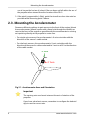
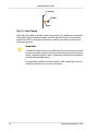
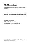
PB-3 Propeller Balancer
User Manual
Smart Avionics Ltd.
Revision: 7
www.smartavionics.com
06/11/2013
PB-3 Propeller Balancer: User Manual
Copyright © 2003-2013 Smart Avionics Ltd.
Android is a trademark of Google Inc.
Bluetooth is a registered trademark of Bluetooth SIG Inc.
Table of Contents
1. Introduction ................................................................................................. 1
1.1. Balancing System Overview ............................................................ 1
1.2. PB-3 Rear Panel ............................................................................... 2
1.3. Battery Charging ............................................................................... 3
1.4. Replacing the Battery ....................................................................... 4
2. Preparing for Propeller Balancing .............................................................. 5
2.1. Additional Items Required ................................................................ 5
2.2. Positioning the Aircraft ..................................................................... 5
2.3. Mounting the Accelerometer ............................................................ 6
2.4. Mounting the PB-3 ........................................................................... 8
2.5. Attaching the Reflective Tape ........................................................ 10
2.6. Attaching the Cable ........................................................................ 11
3. Upgrading the PB-3's Firmware ............................................................... 13
3.1. Upgrading Using a Linux System .................................................. 13
3.1.1. Example lpc21isp output ..................................................... 14
3.2. Upgrading Using a Windows System ............................................ 14
A. Software Licences .................................................................................... 17
A.1. KISS FFT Library ............................................................................ 17
B. EMC Compliance ....................................................................................... 19
C. CE Declaration of Conformity ................................................................... 21
Index .............................................................................................................. 23
www.smartavionics.com
iii
iv
www.smartavionics.com
List of Figures
1.1. PB-3 Hardware ......................................................................................... 1
1.2. PB-3 Rear Panel ....................................................................................... 2
2.1. Accelerometer Axes and Orientation ...................................................... 6
2.2. Accelerometer Mounted on a Rotax 912 Gearbox .................................. 7
2.3. PB-3 on a Europa Cowling ....................................................................... 9
2.4. PB-3 Angle of Incidence .......................................................................... 9
2.5. PB-3 and Reflective Tape ...................................................................... 11
2.6. Cable Taping .......................................................................................... 12
www.smartavionics.com
v
vi
www.smartavionics.com
Chapter 1. Introduction
This manual describes the Smart Avionics PB-3 product and how it is used
in a propeller balancing system.
The PB-3 is marked with this warning symbol to indicate that
it emits bright light (optical radiation).
When the PB-3 is active, it emits infrared light from the red panel
in a narrow, concentrated beam. This invisible light could irritate
or otherwise damage the human eye if viewed at close range.
Do not look directly into the red panel when the PB-3 is on.
1.1. Balancing System Overview
The propeller balancing system has these main components:
Accelerometer
This is mounted on the front of the engine to detect the
vibration due to propeller imbalance.
Optical
tachometer
A strip of reflective tape is attached to one propeller blade
and an optical sensor detects the tape as it passes and
generates the tachometer signal required by the balancer.
Signal processor This digitises the vibration signal and sends the resulting
data to an Android device using Bluetooth® wireless
communications.
Android™ device
This provides the user interface as described in the
Propeller Balancer App User Manual.
Fig 1.1. PB-3 Hardware
The PB-3 combines the optical tachometer and the signal processor into one
lightweight unit. Typically, the PB-3 is attached to the outside of the aircraft's
www.smartavionics.com
1
PB-3 Rear Panel
engine cowling such that the optical sensor can “see” the reflective tape on
the propeller blade through the red panel.
Optionally, the PB-3 can use an externally generated tachometer signal that
provides one pulse per revolution.
1.2. PB-3 Rear Panel
Charge
LED
On/Off
Switch
Activity
LED
External
Tachometer
Connector
OFF
ON
micro USB
Socket
Accelerometer
Connector
Fig 1.2. PB-3 Rear Panel
The rear panel contains:
On/Off switch
This functions in the obvious manner but note that to
save battery power, the PB-3 will turn itself off after 30
minutes of inactivity. If that happens, to turn the PB-3 on
again, simply return the switch to the OFF position and
then back to the ON position.
Charge LED
Illuminated when the PB-3 is being charged:
Green
(continuous)
Battery is charging.
Green (flashing)
Battery is fully charged – disconnect
the charger.
Red (continuous) Fault indication – disconnect the
charger and contact Smart Avionics
for advice.
Red (flashing)
Activity LED
Battery temperature is outside the
allowed range for charging.
A red LED that indicates PB-3 activity:
Off
Unit is off.
One flash every 2 Unit is on but not currently connected
seconds
to an Android device.
2
www.smartavionics.com
Battery Charging
Two flashes every Unit is connected to an Android
2 seconds
device.
When the tachometer is active, the LED function will be
inverted (mostly on instead of mostly off).
Micro USB socket Used for charging the PB-3 and upgrading the device's
firmware.
Accelerometer
connector
Connects to the accelerometer mounted on the engine.
External
tachometer
connector
Connects to an (optional) external tachometer. An external
tachometer must be used for gyroplane rotor balancing.
1.3. Battery Charging
The PB-3's battery is charged via the micro USB socket located on the rear
panel. Any 5V charger fitted with a micro USB-B plug that can supply a
minimum of 450mA may be used to charge the PB-3 (e.g. most modern mobile
phone chargers). The PB-3 itself limits the charge current so the maximum
current supplied by the charger is irrelevant.
The PB-3 can also be charged by connecting it directly to a computer's USB
port using a cable that has a USB-A plug at one end and a micro USB-B plug
at the other end. Do not connect the PB-3 to an unpowered hub.
When the power source is connected, the PB-3's charge LED will be
continuously green while the battery is charging and will flash green when
the battery becomes fully charged.
When the battery is fully charged, disconnect the PB-3 from the power source.
It takes approximately 2.5 hours to recharge a completely flat battery.
Note
The PB-3 may be switched on while charging but if you leave it
switched on, it will increase the time taken to charge the battery
and also it may stop the charge LED from flashing when the battery
has become fully charged.
Important
Only charge the battery when the ambient temperature is greater
than 0°C (32°F) and less than 40°C (104°F) – if the PB-3's internal
temperature is outside of this range, the charge LED will flash red.
www.smartavionics.com
3
Replacing the Battery
Make sure the PB-3 is not exposed to direct sunlight while it is
being charged as this could cause the upper temperature limit to
be exceeded.
If you are not going to use the PB-3 for some time (months), it is best to store
it with the battery approximately 50% charged.
1.4. Replacing the Battery
The PB-3 is powered by a single 3.7V 800mAh Lithium Ion battery of type
Samsung AB463446BU. To replace the battery follow these steps:
1. Disconnect all cables from the PB-3 and ensure it is switched off.
2. Remove the 4 visible screws on the base of the unit and remove the top
cover. The battery is contained within a plastic holder that is attached to
the top circuit board. The holder incorporates a flexible tab that clips onto
the base of the battery to keep it in place.
3. Grip either side of the base of the battery and gently lift the flexible tab
sufficiently so that the battery can be removed by pulling it away from the
3 pronged connector. To avoid damaging the flexible tab, take care not to
lift the tab too far (no more than 5mm) and keep the battery parallel to the
circuit board as it is being removed.
4. To install the new battery, gently lift the tab a little so you can insert the
battery and push the battery forward to locate the 3 prongs of the connector
into the 3 recesses on the top end of the battery. You may need to wiggle
the battery slightly from side to side to allow the prongs to make contact.
Push the battery as far forward as it will go. It should then be possible to
press the end of the plastic tab down so that it grips the base of the battery.
5. Check that the battery is correctly installed by momentarily switching the
PB-3 on and verifying that the LED flashes as normal. If necessary, adjust
the position of the battery by raising the flexible tab, withdrawing the battery
1 cm or so, and then pushing it home again taking care to ensure that the
prongs of the battery connector go into the recesses on the top of the
battery.
6. Replace the top cover noting that the shallow cutouts in one of the flanges
should be at the rear end of the PB-3 to clear the connectors. Replace the
4 screws which should be screwed fully home but not overtightened.
7. The old battery must be disposed of according to local regulations. Do not
dispose of it in the household waste and do not damage it in any way.
4
www.smartavionics.com
Chapter 2. Preparing for Propeller
Balancing
Caution
Propellers can kill.
Make sure that the ignition is switched off before touching the
propeller.
Always assume that the engine could fire when the propeller is
being moved.
Make sure that the aircraft is securely chocked or tied down while
carrying out the balancing process.
2.1. Additional Items Required
To carry out the balancing process, you will need the following items in
addition to the balancer kit:
• Balance weights (typically AN970 washers) and a means of securely
attaching them to the spinner backplate.
A scale for measuring the weights is useful but not absolutely essential as
the balancer works in terms of relative weight rather than absolute weight.
• If necessary, a bracket for mounting the accelerometer onto the front of
the engine (optional, depending on engine type and installation details).
An M6 screw and washer are supplied which can be used to attach the
accelerometer to the back of a Rotax 4-stroke gearbox if the vacuum pump
option is not fitted.
• A roll of 25mm wide masking tape.
2.2. Positioning the Aircraft
The following points should be observed regarding positioning the aircraft
for a propeller balancing session:
1. The position must be safe for ground running of the engine. Typically, the
engine will need to be run at cruise RPM and the aircraft should be braked
and chocked and, if necessary, tied down.
2. When deciding where to locate the PB-3, the position of the aircraft should
be such that direct sunlight will not fall onto the PB-3's red window. If the
www.smartavionics.com
5
Mounting the Accelerometer
sun is low on the horizon it is best if the sun does not fall within the arc of
the propeller when viewed from the location of the PB-3.
3. If the wind is appreciable (> 5kts), point the aircraft as close into wind as
possible while observing point 2 above.
2.3. Mounting the Accelerometer
Remove sufficient cowlings to gain access to the front of the engine. Mount
the accelerometer (40mm square with a 6mm hole through the middle) as
near to the front of the engine as possible with the accelerometer's sensing
axis pointing directly at the propeller's centre line.
• For single axis sensors, the accelerometer's X axis coincides with the
direction of the sensor's cable socket.
• For dual axis sensors, the accelerometer's X axis coincides with the
direction of the sensor's cable socket and its Y axis is at 90° to the direction
of the cable socket.
X Axis
Y Axis
Fig 2.1. Accelerometer Axes and Orientation
Important
The sensing axis used must intersect the axis of rotation of the
propeller.
If you have a dual axis sensor, remember to configure the Android
App to use the correct axis.
6
www.smartavionics.com
Mounting the Accelerometer
Note that the accelerometer does not have to be directly above the propeller's
axis of rotation. However, to get the best results you should not mount the
accelerometer such that the sensing axis is parallel with the engine's cylinders.
On a Rotax 4-stroke engine that doesn't have a vacuum pump attached, the
best place to mount the accelerometer is on the rear of the gearbox using
one of the available tapped holes and the supplied M6 screw and washer.
Fig 2.2. Accelerometer Mounted on a Rotax 912 Gearbox
If the accelerometer cannot be bolted directly to the engine, some form of
bracket will be required. Obviously, the details of this are engine specific but
it could be as simple as a strip of metal with a hole drilled at each end. If a
bracket is used, it must be sufficiently stiff to ensure that the accelerometer
does not move with respect to the engine.
However the accelerometer is mounted, it must not be subjected to excessive
temperatures. The temperature of the sensor should not exceed 85° C. If
necessary, thermally insulating material can be sandwiched between the
accelerometer and the engine (or bracket) to reduce the amount of heat
conducted to the accelerometer. If the surrounding area will be very hot, the
accelerometer could be wrapped in thermally insulating material (once the
cable has been attached).
Important
The accelerometer is robust but may be damaged if dropped on a
hard surface.
It is preferable to refit the engine cowling to minimise the turbulence generated
by the airflow from the propeller. For some aircraft, the cowling will have to
be refitted to provide a suitable mounting position for the optical sensor.
www.smartavionics.com
7
Mounting the PB-3
However, if the balance weights are to be added to the rear of the spinner
backplate, it may pay to leave the cowling off (if possible) during the balancing
process so that it is easier to gain access to the weights. Once the balancing
has been completed, the cowling could be replaced and a final reading taken
to determine the level of vibration achieved.
2.4. Mounting the PB-3
Owing to the variation in aircraft cowling shapes and sizes, only generic
instructions can be provided here. You may find that a little experimentation
is required to obtain the best results. A rectangle of flexible plastic is supplied
that attaches to the PB-3 using Velcro™ tape. This rectangle is first taped to
the outside of the cowling using masking tape and the PB-3 is then firmly
pressed against it.
Caution
This method of mounting the PB-3 on the cowling is perfectly
adequate when the aircraft is stationary on the ground. Under no
circumstances should the aircraft be flown with the PB-3 attached
in this way.
Caution
If the propeller is a pusher, i.e. the cowling is in front of the propeller
rather than behind, extra care should be taken to ensure that the
PB-3 cannot become detached from the cowling and hit the
propeller blades. As a minimum, tape the accelerometer cable to
the cowling so that it will restrain the PB-3 in the event of it
becoming detached from the cowling. If you have any doubt as to
the security of the PB-3, don't risk destroying it and the propeller.
Position the PB-3 such that the red panel is pointing towards the propeller.
If the PB-3's orientation is correct, the blades will sweep across the width of
the red panel as the propeller rotates. The distance from the front of the sensor
to the propeller should be in the range 15-25cm.
8
www.smartavionics.com
Mounting the PB-3
Fig 2.3. PB-3 on a Europa Cowling
Fig 2.3 shows the PB-3 mounted on the side of a Europa classic cowling.
Notice how it is angled slightly up to ensure that the angle of the infrared
beam relative to the rear surface of the propeller is approximately 30°.
Important
To detect the propeller RPM reliably, the PB-3 must be positioned
such that the angle of the infrared beam relative to the face of the
propeller blade is approximately 30° from the normal (either in front
of or behind the normal). Fig 2.4 illustrates this.
Normal
Approx 30 degrees
angle of incidence
(from normal)
PB-3
Fig 2.4. PB-3 Angle of Incidence
www.smartavionics.com
9
Attaching the Reflective Tape
If the angle is too small, the PB-3 will tend to detect the other blades
(especially if they are highly reflective) and the RPM will appear
erratically too high. If the angle is too large, the blade with the
reflective tape will not be reliably detected and the RPM will appear
zero or erratically too low.
2.5. Attaching the Reflective Tape
With the engine ignition switched off, rotate the propeller so that one blade
lies directly on the sensing axis of the PB-3, i.e. if you could see through the
blade you would be looking directly into the sensor's red panel. Make sure
that the area on the back of the blade where the tape is going to be attached
is clean. Apply a strip of 25mm wide masking tape to the back of the propeller
at the point that the infrared beam will hit the blade. Wrap the tape a short
distance around the leading edge of the blade but don't wrap it around the
trailing edge.
Important
The tape must be oriented such that it is parallel to the PB-3's red
panel. This may mean that the tape is not at 90° to the leading edge
of the blade but that doesn't matter. The important point is that the
tape is parallel with the red panel.
Now put a strip of the reflective tape on top of the masking tape. Again, wrap
the tape a little way around the leading edge of the propeller to stop it peeling
back. The purpose of the masking tape is simply to make it easy to remove
the (very thin) reflecting tape when the job is done.
Fig 2.5 shows the PB-3 mounted on the side of a Europa classic cowling and
the reflective tape attached to the rear face of a propeller blade.
10
www.smartavionics.com
Attaching the Cable
Fig 2.5. PB-3 and Reflective Tape
If you subsequently find that the optical tachometer cannot reliably detect
the RPM, verify that the tape really is in the correct position. You may find
that adding another strip of reflective tape next to the first strip will improve
the situation.
Note
The Bluetooth radio signal cannot pass through metal so if the
PB-3 is mounted on a metal cowling, you should not expect it to
be able to communicate with the Android device when the cowling
is between the two units.
In practice, that means that it is unlikely you will be able to operate
the balancer from within a metal aircraft's cockpit. It will work when
you are positioned such that the radio signals can reach you without
passing through the aircraft's structure (i.e. you are standing on
the side of the aircraft that the PB-3 is attached to).
2.6. Attaching the Cable
Connect the accelerometer to the PB-3 using the supplied cable and make
sure the connectors' retaining collars are screwed down (take care to only
rotate the metal retaining collar and not the plastic body of the connector).
Any slack in the cable should be taken up by coiling the cable and then
applying a few strategically placed pieces of masking tape to stop the cable
flapping around in the propeller breeze.
www.smartavionics.com
11
Attaching the Cable
Cowling
Cable
Tape
Fig 2.6. Cable Taping
If you tape the cable as shown in the above figure, it is unlikely to come adrift.
Taping the cable securely provides an extra benefit in that, in the unlikely
event of the PB-3 coming away from the cowling, the cable should stop it
hitting the ground.
Important
To obtain the best results, the cable from the accelerometer should
be kept away from sources of electrical interference such as ignition
leads, magnetos/ignition units, generators/alternators/regulators
and their associated wiring.
Be especially careful to ensure that the cable cannot get close to
rotating components or very hot surfaces.
12
www.smartavionics.com
Chapter 3. Upgrading the PB-3's Firmware
The PB-3's firmware can be upgraded by connecting the PB-3 to a PC with
a USB cable and then using a simple command line program, lpc21isp, to
send the firmware to the PB-3. Ready to use versions of this program for both
Linux and Windows™ systems are available on the Smart Avionics website.
The new balancer firmware will be named pb3-version.hex, where
version is the firmware version number.
3.1. Upgrading Using a Linux System
If you are using a Linux system, follow these steps:
1. Download the new firmware file and the lpc21isp program from the Smart
Avionics website and save them in a convenient directory.
2. Open a command shell and cd to the directory containing the saved files.
The lpc21isp program is zipped into an archive, so extract it and (to make
your life easier) rename (mv) the executable to lpc21isp.
3. When you connect the PB-3 to the PC using a USB cable it will appear as
a new USB serial device. We need to access that device by name. Linux
systems generally name the USB serial devices with names like
/dev/ttyUSBx where x is a number.
Before you plug the USB cable into the PB-3, execute the following
command to list the names of any USB serial devices already present:
ls /dev/ttyUSB*
You will either see a list of names or, if no USB serial devices are presently
connected to your system, ls will gripe because the wildcard (*) didn't
match anything.
4. Plug the PB-3 into the USB cable, switch it on and list the USB serial devices
again. You should now see the PB-3's serial device name added to the list.
5. To send the firmware to the PB-3 execute:
./lpc21isp -control pb3-version.hex /dev/ttyUSBx 115200 12000
Where pb3-version.hex is the name of the file containing the new
firmware and /dev/ttyUSBx is the name of the PB-3's serial device.
www.smartavionics.com
13
Example lpc21isp output
Note
Some systems may require you to be logged in as root to access
the USB serial devices.
The lpc21isp program should display diagnostic output similar to the
example shown below (the lines have been shortened to fit the page).
6. Once the download has finished, you can switch off the PB-3 and
disconnect the USB cable.
3.1.1. Example lpc21isp output
lpc21isp version 1.74
File pb3.hex:
loaded...
converted to binary format...
image size : 90640
Image size : 90640
Synchronizing (ESC to abort). OK
Read bootcode version: 1
4
Read part ID: LPC1758, 512 kiB ROM / 64 kiB SRAM (0x25013F37)
Will start programming at Sector 1 if possible, and conclude
with Sector 0 to ensure that checksum is written last.
Erasing sector 0 first, to invalidate checksum. OK
Sector 1: ...............................................
Sector 2: ...............................................
Sector 3: ...............................................
Sector 4: ...............................................
Sector 5: ...............................................
Sector 6: ...............................................
Sector 7: ...............................................
Sector 8: ...............................................
Sector 9: ...............................................
Sector 10: ..............................................
Sector 11: ..............................................
Sector 12: ..............................................
Sector 13: ..............................................
Sector 14: ..............................................
Sector 15: ..............................................
Sector 16: ..............................................
Sector 0: ...............................................
Download Finished... taking 20 seconds
Now launching the brand new code
3.2. Upgrading Using a Windows System
If you are using a Windows™ system, follow these steps:
14
www.smartavionics.com
Upgrading Using a Windows System
1. Windows computers must have the VCP (Virtual Comm Port) driver
installed. The drivers can be downloaded from:
http://www.ftdichip.com/Drivers/VCP.htm.
Please follow the FTDI instructions to install the driver.
2. Download the new firmware and the lpc21isp program from the Smart
Avionics website and save them in a convenient folder.
The lpc21isp program is zipped into an archive, so extract it and (to make
your life easier) rename the executable lpc21isp.exe.
3. Connect the PB-3 to the PC with the USB cable and switch the PB-3 on.
Go to My Computer > Manage > Device Manager > Ports (COM & LPT) and
it should show an entry like: USB Serial Port (COMx) where x is a
number.
4. Open a Command Prompt window (Start Menu > Programs > Accessories
> Command Prompt) and using the cd command go to the directory (folder)
containing the downloaded PB-3 firmware and the lpc21isp program. Now
execute the following command:
.\lpc21isp -control pb3-version.hex COMx 115200 12000
Where pb3-version.hex is the name of the file containing the new
firmware and COMx is the name of the serial device corresponding to the
PB-3.
The lpc21isp program should display diagnostic output similar to that
shown in Section 3.1.1.
5. Once the download has finished, you can switch off the PB-3 and
disconnect the USB cable.
www.smartavionics.com
15
16
www.smartavionics.com
Appendix A. Software Licences
The PB-3 uses the following 3rd party software packages.
A.1. KISS FFT Library
Copyright (c) 2003-2004 Mark Borgerding
All rights reserved.
Redistribution and use in source and binary forms, with or without
modification, are permitted provided that the following conditions are met:
• Redistributions of source code must retain the above copyright notice, this
list of conditions and the following disclaimer.
• Redistributions in binary form must reproduce the above copyright notice,
this list of conditions and the following disclaimer in the documentation
and/or other materials provided with the distribution.
• Neither the author nor the names of any contributors may be used to
endorse or promote products derived from this software without specific
prior written permission.
THIS SOFTWARE IS PROVIDED BY THE COPYRIGHT HOLDERS AND
CONTRIBUTORS "AS IS" AND ANY EXPRESS OR IMPLIED WARRANTIES,
INCLUDING, BUT NOT LIMITED TO, THE IMPLIED WARRANTIES OF
MERCHANTABILITY AND FITNESS FOR A PARTICULAR PURPOSE ARE
DISCLAIMED. IN NO EVENT SHALL THE COPYRIGHT OWNER OR
CONTRIBUTORS BE LIABLE FOR ANY DIRECT, INDIRECT, INCIDENTAL,
SPECIAL, EXEMPLARY, OR CONSEQUENTIAL DAMAGES (INCLUDING, BUT
NOT LIMITED TO, PROCUREMENT OF SUBSTITUTE GOODS OR SERVICES;
LOSS OF USE, DATA, OR PROFITS; OR BUSINESS INTERRUPTION) HOWEVER
CAUSED AND ON ANY THEORY OF LIABILITY, WHETHER IN CONTRACT,
STRICT LIABILITY, OR TORT (INCLUDING NEGLIGENCE OR OTHERWISE)
ARISING IN ANY WAY OUT OF THE USE OF THIS SOFTWARE, EVEN IF ADVISED
OF THE POSSIBILITY OF SUCH DAMAGE.
www.smartavionics.com
17
18
www.smartavionics.com
Appendix B. EMC Compliance
To ensure EMC compliance, please observe the following conditions when
using the PB-3:
1. Do not use the PB-3 in close proximity to other electrical equipment capable
of generating large amounts of electrical interference.
2. All electrical equipment in the aircraft that is not required for either safety
reasons or to facilitate the running of the engine should be switched off
while the PB-3 is being used.
3. As described in this manual, avoid routing the PB-3's cables near to sources
of electrical interference (such as engine ignition components and cabling).
4. Only use cables approved by Smart Avionics for connecting the sensors
to the PB-3.
www.smartavionics.com
19
20
www.smartavionics.com
Appendix C. CE Declaration of Conformity
We, Smart Avionics Ltd. Chorlton Lane Farm, Chorlton, Malpas,
Cheshire. SY14 7ES. United Kingdom, declare, on our own
responsibility, that the PB-3 conforms with the essential
requirements of the R&TTE Council Directive 1999/5/EC.
Conformity is declared to the following harmonised standards:
EMC
EN61326-1:2006 “Electrical equipment for
measurement, control and laboratory use - EMC
Requirements”.
RF
EN 300328 V1.7.1 (2006-2010) “Electromagnetic
compatibility and Radio spectrum Matters (ERM);
wideband transmission systems; Data transmission
equipment operating in the 2.4 GHz ISM band and
using wideband modulation techniques”.
Safety
IEC 61010-1:2010 (3rd edition) and EN 61010-1:2010
“Safety requirements for electrical equipment for
measurement, control and laboratory use”.
Equipment type: Battery powered portable test/measurement.
Environment: External/Workshop.
I, the undersigned, hereby declare that the PB-3 conforms to
the above Directive.
Mark Burton
Director
Smart Avionics Ltd.
22 June 2012
www.smartavionics.com
21
22
www.smartavionics.com
Index
A
accelerometer
mounting, 6
mounting bracket, 7
sensing axes, 6
temperature, 7
aircraft
positioning, 5
B
balance
weights, 5
battery
charging, 3
replacement, 4
C
cable, 11
F
firmware
upgrading, 13
L
lpc21isp, 13
P
PB-3
angle, 9
mounting, 8
R
reflective tape, 10
W
wind, 6
windows
comm port driver, 14
www.smartavionics.com
23
24
www.smartavionics.com