1
;/;/
6HFXULW\6\VWHP
8VHU*XLGH
9HUVLRQ
N9146-1 10/98
Table Of Contents
Introduction .................................................................................................................................4
LCD Keypad Layout....................................................................................................................5
LED Keypad Layout....................................................................................................................8
System Operation......................................................................................................................12
Arming The System...................................................................................................................13
System Ready ............................................................................................................................13
System Not Ready .....................................................................................................................14
Stay ...............................................................................................................................................16
Stay Procedure ..........................................................................................................................16
Auto-Stay Mode (optional) ........................................................................................................16
Instant ..........................................................................................................................................18
Instant Procedure......................................................................................................................18
Instant – Stay..............................................................................................................................19
Instant – Stay Procedure ..........................................................................................................19
Bypass ..........................................................................................................................................20
Bypass Procedure ......................................................................................................................20
Forced Arming ...........................................................................................................................22
Forced Arming Procedure .........................................................................................................22
Unbypass .....................................................................................................................................23
Unbypass Procedure .................................................................................................................23
Group Bypass (Optional) .........................................................................................................24
Group Bypass Procedure ..........................................................................................................24
Group Unbypass ........................................................................................................................25
Group Unbypass Procedure ......................................................................................................25
User Code Definition ................................................................................................................26
User Definition Procedure ........................................................................................................27
User Deletion..............................................................................................................................29
User Deletion Procedure...........................................................................................................29
Disarming....................................................................................................................................30
Disarm Procedure .....................................................................................................................30
Keypad Auxiliary Conditions .................................................................................................32
Duress...........................................................................................................................................33
Quick Commands ......................................................................................................................34
Common Partition Display [# 0]...............................................................................................34
Quick Arming [# 1]....................................................................................................................36
Quick Forced Arming [# 2]........................................................................................................36
Time Set [# 3] ............................................................................................................................36
Zone Directory [# 4]...................................................................................................................39
Quick Bypassing [# 5] ...............................................................................................................39
Chime Mode [# 6] ......................................................................................................................39
–2–
Table Of Contents (cont’d)
Partition Assignment [# 7] .......................................................................................................40
Glossary .......................................................................................................................................42
Recommendations For Proper Protection..........................................................................45
Recommendations For Smoke And Heat Detectors ................................................................45
Recommendations For Proper Intrusion Protection ...............................................................46
Emergency Evacuation ............................................................................................................47
System Testing ...........................................................................................................................48
Battery Test...............................................................................................................................49
Owners Information .................................................................................................................50
About The Manufacturer.........................................................................................................51
Statements – Problems – Warnings.......................................................................................52
Warranty......................................................................................................................................55
–3–
Introduction
Congratulations on your decision to protect your home or business
with this Security System. The system has been designed with
reliability and ease of operation in mind.
Please take a few minutes to review the contents of this manual. In
order to realize the full potential of this system it is important that
you feel comfortable with its operation. The following pages will
familiarize you with the procedures for operating the Security System.
The system can be operated from different styles of keypads: model
XK-716 and XK-516 LED keypads containing indicator lights or model
XK-7LC and XK-5LC LCD keypads containing a two-line readout.
Please determine the type of keypads present within your system.
This manual covers the XL-4, XL-4B, XL-4C and XL-5 systems. The
systems differ with the following Underwriters applications:
XL-4
Household Burglary and Fire
XL-4B Commercial Burglary
XL-4C Commercial Fire and Burglary
Thank You,
FIRE BURGLARY INSTRUMENTS
NOTE: This owner's manual contains important information and is
not to be removed by anyone but the occupant of the premise.
–4–
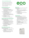
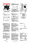
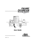
LCD Keypad Layout
The XK-7LC or XK-5LC keypad contains everything necessary to
operate the Security System. The LCD (liquid crystal display) provides
a two line by sixteen-character English readout display to show the
current system status. The keypads appear as follows:
1
2
3
1
2
3
STAY
4
5
6
BYPASS
7
8
9
INSTANT
✴
0
#
CODE
4
9
8
5
6
7
Model XK-7LC LCD Keypad
1
2
5
3
4
7
6
1
2
3
4
5
6
7
8
9
*
0
#
10
Model XK-5LC LCD Keypad
(Shown with Cover Open)
LCD KEYPAD LAYOUT
–5–
LCD Keypad Layout (cont’d)
1 – DISPLAY AREA
Two line by sixteen-character liquid crystal display. This area
contains the current system status using easy to read English
language descriptions programmed by your installer.
2 – ARM/DISARM INDICATOR
This light indicates whether the system is currently armed (activated)
or disarmed (deactivated). In addition to this constant visual
indication, the display area will provide additional information
concerning the current system status. This indicator will blink when
an alarm has occurred.
3 – STAY
The STAY key is used to activate (arm) the system with the exception
of interior protection. This will provide exterior protection of your
location while allowing full access through the premise. This mode
would be used when arming the system and you might be walking
through protected interior zones.
4 – BYPASS
The BYPASS key will be used to temporarily turn off protection to a
portion of your Security System. This could be performed, for example,
to ignore an open window that would prevent the arming of your
system. Certain zones such as FIRE detection zones are always active
and cannot be bypassed.
5 – INSTANT
The INSTANT key is used to activate (arm) the system and eliminates
the entry time delay. This would cause an immediate alarm if
someone came through an exit/entry zone.
6 – CODE
Function key used when entering or changing the User access codes of
your Security System.
–6–
LCD Keypad Layout (cont)
7 – NUMERICAL SECTION
The numerical section of the keypad operates similar to a telephone or
calculator. The digits 0 - 9, # and ✴ are clearly marked and are used to
operate the system.
8 – PULL OPEN DOOR
The front of the XK-7LC keypad contains a door that pulls open.
Behind this door is a card which can be filled out to describe the areas
protected (zones) by your Security System.
9 – AC INDICATOR
This light indicates that AC power is connected to the Security
System. The system also contains battery backup to operate the
system in the event of a power failure.
10 – EMERGENCY KEYS
These keys generate Fire, Medical, or Panic signals when certain key
combinations are entered.
–7–
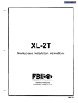
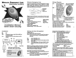
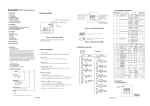
LED Keypad Layout
The LED based system contains indicator lights to display the current
status of your Security System. NOTE: The LED keypads can only be
used to display the status of the first sixteen zones. NOTE: This style
of keypad cannot be used with the XL-4C control panel. The keypad
has the following appearance:
1
2
1
2
3
9
10
11 12
4
5
6
3
7
8
13 14 15
16
4
5 6
7
BAT STAY RDY
COM INS
8
14
1
2
3
STAY
4
5
6
BYPASS
7
8
9
INSTANT
✴
0
#
CODE
9
10
13
11
12
Model XK-716 LED Keypad
1
3
2 3
4
5
6
7
8
4
5
1
2
9
10 11 12 13 14 15 16 COM INS PWR
6 13
BATSTAYRDY
7
10
8
9
14
11
1
2
3
4
5
6
7
8
9
*
0
#
15
Model XK-516 LED Keypad
(Shown with Cover Open)
LED KEYPAD LAYOUT
–8–
LED Keypad Layout (cont’d)
1 – ZONE STATUS
The indicator lights marked 1-16 display the current status of the first
sixteen zones connected to your Security System. The lights show
whether any zones are currently in alarm, bypassed, in trouble, or
faulted (not ready) status. The status of each zone is represented as
follows:
ALARM
Fast Blinking
TROUBLE
Slow Pulse
BYPASSED Slow Low Intensity Blinking
NOT READY Solid ON
Each light will only reflect one condition at a time. If a zone contains
multiple conditions at the same time the highest priority status from
the above list will appear.
2 – COMMUNICATIONS FAILURE
If the COM light BLINKS then there has been a communications error
with the Central Station.
3 – LOW BATTERY
If the BAT indicator BLINKS then the backup battery within the
system is low.
4 – STAY
The STAY light will be ON when the system has been armed in the
stay mode, which means that the system has been activated with the
exception of interior zones.
5 – INSTANT
The INS indicator will be ON when the system has been armed in the
INSTANT mode. This means that the system has been activated and
the entry delay has been eliminated.
–9–
LED Keypad Layout (cont’d)
6 – READY INDICATOR
The light marked RDY shows whether the system is ready to be
armed. If the light is off then a condition exists within at least one of
the zones preventing system arming.
7 – ARM/DISARM INDICATOR
This light indicates whether the system is currently ARMED (ON) or
DISARMED (OFF). In addition to this constant visual indication, the
zone indicator lights will provide additional information concerning
the current zone status. This light will also blink if there is an alarm
condition present.
8 – STAY
The STAY key is used to activate (arm) the system with the exception
of interior protection. This will provide exterior protection of your
location while allowing full access through the location. This mode
would be used when arming the system and you might be walking
through protected interior zones.
9 – BYPASS
The BYPASS key will be used to temporarily turn off protection of a
portion of your burglary protection. This could be performed, for
example, to ignore an open window that would prevent the arming of
your system.
10 – INSTANT
The INSTANT key is used to activate (arm) the system and eliminates
the entry delay. This would cause an immediate alarm if someone
came through an exit/entry zone.
11 – CODE
Function key used when entering or changing the User access codes of
your system.
– 10 –
LED Keypad Layout (cont’d)
12 – PULL OPEN DOOR
The front of the XK-716 keypad contains a door that pulls open.
Behind this door is a card which can be filled out to describe the areas
protected (zones) of your Security System.
13 – AC INDICATOR
This light indicates that AC power is connected to the Security
System. Battery backup exists to operate the system in the event of a
power failure.
14 – NUMERICAL SECTION
The numerical section of the keypad operates similar to a telephone or
calculator. The digits 0 - 9, # and ✴ are clearly marked and are used to
enter commands to the Security System.
15 – EMERGENCY KEYS
These keys generate Fire, Medical, or Panic signals when certain key
combinations are entered.
– 11 –
System Operation
Throughout this manual the following notation will be used to
describe action taken at the keypads:
BYPASS
INSTANT
STAY
CODE
[USER]
✴
#
+
☞
– 12 –
Depression of the Function Key labeled BYPASS
Depression of the Function Key labeled INSTANT
Depression of the Function Key labeled STAY
Depression of the Function Key labeled CODE
Entry of your user code (see note below)
Key labeled ✴ (located to the left of 0)
Key labeled # (located to the right of 0)
Indicates the simultaneous depression of two keys.
For example, # + 3 indicates that the # and 3 keys
should be pressed at the same time.
USER CODE NOTE: The [USER] code can be selected by your
installer to be either a four or seven digit code. If a seven-digit
user code is selected then the user code will be the three-digit
user number followed by the four-digit user code. For example, if
user number 3 has a code of 6429 then the seven digit user code
would be 0036429.
Arming The System
ARMING the system will activate all portions of your Security
System. Arming can only be performed if all zones are READY. For
example, if a protected door is open the system cannot be armed.
☞
Note: Your installer can program your system to be armed if
certain zones are not ready. Contact your installer to determine
whether this applies to your system.
System Ready
Ready Indications
LCD Based Keypads
If the system is ready to be armed the following message will appear
in the display area of the LCD keypad:
SYSTEM READY
The second line of the display can display a system wide descriptor
(example SMITH RESIDENCE) and may scroll through other system
conditions that are present.
LED Based Keypads
On LED keypads the READY indicator must be ON.
Arming Procedure
Enter your user code into the keypad:
[USER]
On LCD keypads the following display appears:
ON:AWAY ……
... Exit Now .....
The ARMED indicator light will now be lit (LED and LCD keypads)
and you may exit through a door designated by your installer as an
exit/entry zone for a fixed time period known as the exit delay. Once
the exit time period has expired the EXIT NOW indication will
disappear.
Your exit time is _______
Your entry time is _______
– 13 –
Arming The System (cont’d)
System Not Ready
Ready Indications
LCD Based Keypads
If the system is not ready to be armed the LCD display will display
the zone or zones not ready as follows. For example:
NOT READY Zne 012
Master Bedroom
This display indicates that zone number 12 is not ready. This might
mean that a window or door remains open. When the problem with
zone 12 has been resolved, the READY display will appear. The zones
correspond to the areas of protection set up by your installer.
☞
Note: If more than one zone is not ready then the display will
scroll through the zones approximately every 2 seconds.
LED Based Keypads
On the LED keypads the individual zone lights display the zones
which are not ready as follows:
ALARM
Fast Blinking
BYPASS
Slow blinking low intensity
TROUBLE
Slow Pulse
NOT READY Solid ON
Action Required
If the system is NOT READY, one of the following actions is required
if you want to ARM the system:
- Make the zone(s) ready. Determine which zones are not ready by
looking at the keypad and perform what is necessary to ready the
zone(s). For example if zone 12 represents the Bedroom Window,
then closing the window should make that zone ready.
or
- Bypass the zone(s) not ready. Bypassing should only be performed if
the zone cannot be made ready or intentionally will remain not
– 14 –
Arming The System (cont’d)
ready. Zones that are bypassed are not protected when the system
is armed.
NOTE: It is possible to arm the system without the back-up battery
connected.
NOTE: In a commercial burglary alarm installation (model XL-4B or
XL-4C) a brief pulsing audible output is provided by the keypad to
indicate successful receipt of the closing signal at the Central Station.
If not heard, CALL FOR SERVICE.
In a commercial burglary installation (model XL-4B) the bell will
energize briefly after entry of the user code during arming. If not
heard, CALL FOR SERVICE.
– 15 –
Stay
The STAY mode is another way to ARM your system while you remain
in the location. The STAY mode will deactivate any interior protection
zones, which means that you will be free to walk throughout your
location without activating the alarm system.
In order to enter the STAY mode, the system must be ready. (See
previous description).
Stay Procedure
Stay [USER]
Depress the STAY key followed by your user code.
☞
Remember that you must DISARM the system to leave the
premise.
Note: The STAY option will automatically be reset after the system is
disarmed.
Indications
LCD Keypads
After a successful STAY arming the following display will appear:
ON: STAY . . . . . . .
In addition, the ARMED indicator will be lit. In the STAY mode only
the external or perimeter burglary protection is active. You are free to
walk around the location without activating any of the interior
protection zones.
LED Keypads
On LED keypads both the ARMED and STAY lights will be lit.
Auto-Stay Mode (optional)
Another option that can be programmed by your installer is the
Auto-Stay mode. This feature will arm the system and will bypass
only those interior zones preselected by your installer. For example, you
– 16 –
Stay (cont’d)
can stay in your location and walk freely through the living section of
your location and have certain portions of the interior protection
active in the rest of your home.
To auto stay arm simply enter your user code [USER] and remain
within the location (do not leave through the exit/entry door). This will
arm the system and only bypass those interior zones selected by your
installer. LCD keypads will contain the following display:
ON: AUTO STAY . . . .
– 17 –
Instant
The INSTANT mode arms the system and eliminates the entry and
exit time delay intervals. If anyone enters or exits through an
entry/exit zone the alarm system will instantly activate.
The system must be READY to select the INSTANT option.
Instant Procedure
Instant [USER]
Depress the INSTANT key followed by your user code.
Note: The INSTANT option will automatically be reset after the
system is disarmed.
Indications
LCD Keypads
Upon successful INSTANT ARMING of the system the ARMED
indicator will be lit and the following display appears:
ON: AWAY INSTANT
LED Keypads
Upon successful INSTANT arming of the system the ARMED and
INSTANT indicators will be lit.
– 18 –
Instant – Stay
The INSTANT STAY mode will arm the system with the
characteristics of both the INSTANT and STAY modes. The system
will be armed with the interior portions bypassed and the entry delay
will be suspended.
The system must be READY in order to enter this mode.
Instant – Stay Procedure
INSTANT STAY [USER]
or
STAY INSTANT [USER]
Depress the INSTANT and STAY keys in any order followed by your
user code.
Indications
LCD Keypads
ON: STAY INSTANT
LED Keypads
After a successful INSTANT STAY arming the ARMED, STAY and
INSTANT indicators will be lit.
– 19 –
Bypass
Bypasses are performed to eliminate burglary zones that are not ready
or faulty from activating the Security System.
Bypass Procedure
BYPASS [USER] ZN
Depress the BYPASS key followed by your user code and the three
digit zone number (000 - 072) to be bypassed.
The zone number to be bypassed is shown as ZN. For example, if your
user code is 7356 and you want to bypass zone 16 enter:
BYPASS 7 3 5 6 0 1 6
Press the bypass key followed by 7 3 5 6 (your user code), and 0 1 6
(desired zone to be bypassed).
Multiple zones may be bypassed by repeating the sequence for the
desired zones within a fifteen-second time period as follows:
EXAMPLE:
BYPASS [USER] 002 BYPASS 056 BYPASS 071
The sequence displayed above would have bypassed zones 2, 56 and
71.
Zones can be bypassed if the user performing the bypass is authorized
to perform bypasses and the zone has been defined by your installer as
bypassable.
If the zone has already been bypassed, the sequence will unbypass the
zone except if the system is armed and the unbypassed zone is still not
ready. Unbypass means that the zone returns as an active burglary
zone.
After the bypass (or unbypass) command has been accepted the unit
will emit a continuous beep and keypads will display the bypassed
zones as follows:
– 20 –
Bypass (cont’d)
LCD Keypads
BYPASSED Zne 002
Upstairs Bedroom
or
UNBYPASS Zne 002
Upstairs Bedroom
LED Keypads
On LED keypads the zone number bypassed will blink slowly in a low
intensity. Note: This only applies to the first 16 zones on LED
keypads.
Immediately Arm
To immediately ARM the system enter [USER] after the last zone
bypass.
NOTE: Zones that are bypassed are not protected when the system is
armed.
– 21 –
Forced Arming
Forced Arming is a method that will automatically bypass all faulted
zones and ARM the system. NOTE: This capability must be selected
by your installer at the time of system installation.
Forced Arming Procedure
BYPASS [USER] BYPASS
Depress the BYPASS key followed by your user code and the BYPASS
key.
If any of the zones currently faulted are not bypassable, then the
command will not succeed, and a long interrupted beep will follow.
Following a successful forced arming the ARMED indicator will be lit
and the ON:AWAY display will appear on LCD keypads.
NOTE: This feature is NOT enabled for UL applications.
– 22 –
Unbypass
The UNBYPASS function removes an existing bypass from a currently
bypassed zone.
The procedure is similar to a bypass.
Unbypass Procedure
BYPASS [USER] ZN
To remove a bypass from a zone already bypassed press the BYPASS
key, followed by your user code and the three digit zone number.
See bypass description.
NOTE: In UL Listed systems, bypasses are automatically removed
upon disarming.
– 23 –
Group Bypass (Optional)
Your installer can designate multiple zones within your location to be
known as a group. For example, if your location has two floors, the
zones on the upper level can be a separate group from the lower level.
Each zone within the group will display an individual zone
identification on the keypad, however there are commands to bypass
the entire group at once. Consult with your installer to determine
whether groups exist within your location.
Group Bypass Procedure
BYPASS [USER] ✴ 1 Group
Press the BYPASS key, followed by your user code, the digits ✴ 1, and
the group number (01 - 24) as designated by your installer.
Example: Perform a group bypass on group 3 (assume a user code of
2468)
BYPASS 2 4 6 8 ✴ 1 0 3
The system will bypass all of the zones within that group, and the
keypad will display the bypassed zones as described in the BYPASS
section.
Remember that zones bypassed are not protected when the system is
armed.
– 24 –
Group Unbypass
To remove bypasses from all of the zones within a group, the group
unbypass command can be performed. This will remove the bypasses
from all of the zones within a group. See group bypass section for more
details.
Group Unbypass Procedure
BYPASS [USER] ✴ 2 Group
Press the BYPASS key, followed by your user code, the digits ✴ 2, and
the group number (01 - 24) as designated by your installer.
Example: Perform a group unbypass on group 3 (assume a user code of
2468):
BYPASS 2 4 6 8 ✴ 2 0 3
– 25 –
User Code Definition
User codes are required to operate your Security System. Users can be
entered or modified directly through the keypad. The Security System
contains up to 64 (XL-4) or 128 (XL-5) separate user codes. Authorized
users can modify user codes directly through the keypad. Each of the
User codes have the following characteristics:
USER ID- This is the code entered at the keypad to operate the
Security System. Each separate user must be assigned a unique user
code. The user ID has been displayed as [USER] throughout this
manual.
USER NUMBER- Sequence number identifying the user being
modified or entered. The user numbers range from 001 to 064 (XL-4)
or from 001 to 128 (XL-5).
AUTHORIZATION LEVEL- The control panel contains
authorization levels to control the users permitted to perform various
system functions. This allows users to be restricted to certain
functions. The levels are shown below:
LEVEL 1 - ARM, DISARM, BYPASS, PROGRAM USERS,
CHANGE PARTITION ASSIGNMENTS IN ALL PARTITIONS
This would be the highest level user and would be able to perform
all functions within all partitions (subsystems).
☞
User Code 1 should always be set to a Level 1.
LEVEL 2 - ARM, DISARM, BYPASS, PROGRAM USERS,
CHANGE PARTITION ASSIGNMENTS IN OWN PARTITION
This level of user would be able to perform all functions and would
be able to change user partition access only within the partitions
(subsystems) where the user is assigned.
LEVEL 3 - ARM, DISARM, BYPASS, PROGRAM USERS
LEVEL 4 - ARM, DISARM, BYPASS
LEVEL 5 - ARM, DISARM
– 26 –
User Code Definition (cont’d)
LEVEL 6 - DURESS CODE
A DURESS code is a special user code that will ARM the system and
transmit a special emergency signal.
LEVEL 7 - ARM ONLY
This level of user code could be assigned to a maid, babysitter, or
maintenance worker and would only be able to ARM the system.
User Definition Procedure
Code [USER]
Depress the CODE key followed by your user access code. Assuming
that the user is valid for user definition the following displays will
appear on LCD keypads:
XL-4
ENTER USER #
001-064, ✴ to Exit
XL-5
ENTER USER #
001-128, ✴ to Exit
Enter the user number to be entered or modified. The user number
must be entered as a three-digit value: for example user #3 will be
entered as 003.
ENTER User CODE
✴ exit, # erase
Enter the desired four-digit user code. The user code entered (0001 9999) must be unique and cannot be duplicated with another user code
within the system. If an invalid code is entered, the keypad will beep
four times and the keypad will repeat the question. NOTE: If a seven
digit user code has been selected by your installer then the user code
will be the user number followed by this four digit user code. For
example, user number 015 with a code of 9876 would require entry of
0159876 when operating the Security System.
– 27 –
User Code Definition (cont’d)
ENTER Authority
1 - 7, ✴ to Exit
Enter the authorization level of the user being defined from the list
provided above.
If an error is detected after any of the user questions the keypad will
beep rapidly four times and repeat the question.
☞
NOTE: To exit from the User definition displays press the ✴ key.
The procedure for defining users from an LED keypad is identical
except that the display prompts will not appear.
– 28 –
User Deletion
Removal of users from the panel can be performed as follows:
User Deletion Procedure
CODE [USER] [User #] #
Where:
[USER] User code (must be level 1 or 2 authorization level)
[User #] Represents the user number being deleted. [000 - 064]
User deletion can only be performed by a level 1 or level 2
authorization user.
Example: Delete user number 4. (Assume a level 1 user code of 2468)
CODE 2468 004 #
The deletion procedure should be used only when the user being
removed is not being replaced with another user code.
– 29 –
Disarming
Disarming the Security System will deactivate the burglary portions
of the system.
Disarm Procedure
[USER]
Enter your user code.
If No Alarms Have Taken Place
The system will be disarmed and the ARMING indicator will go off.
The system display will reflect the current status.
If Alarms Have Taken Place
If alarms or other conditions such as system troubles have taken place
since the initial system arming, they will appear on the keypad as
follows:
LCD Keypads
If more than one condition has occurred then they will scroll on the
display approximately every two seconds. For example,
BURGLARY
zn 012
MASTER BEDROOM
BURGLARY
LIVING ROOM
zn 005
FIRE
zn 064
Basement Smoke
To silence the keypad enter your USER code. You can also use the
reset command (depression of the 3 and 1 keys together, or the ✴ key)
if your installer has enabled the function.
– 30 –
Disarming (cont’d)
After scrolling through the alarms or troubles, the display will contain
the first alarm and repeat the sequence of condition signals until the
display has been cleared.
To clear the display of the conditions enter your user code again.
☞
IMPORTANT: If there have been alarms DO NOT ENTER THE
PREMISE, call for help from a neighbor's telephone.
LED Keypads
If alarms or other system conditions such as troubles have occurred
since the initial system arming, they will appear in the zone display
portion of the keypad as follows:
ALARM
Fast Blinking
TROUBLE
Slow pulse
BYPASS
Slow Low intensity blinking
NOT READY Solid ON
To silence the keypad sounder enter your user code.
To clear the keypad of the alarm conditions enter your user code a
second time.
– 31 –
Keypad Auxiliary Conditions
In addition to individual zone alarms various conditions can be
transmitted directly through the keypad. These conditions are
initiated through the simultaneous depression of two keys, as listed
below:
☞
NOTE: The keypad conditions are active 24 hours a day, whether
the system is armed or disarmed.
Model XK-516 and XK-5LC Keypads
Model XK-716 and XK7LC Keypads
KEYPAD
CONDITION 2
1
2
3
STAY
4
5
6
BYPASS
7
8
9
INSTANT
✴
0
#
KEYPAD
CONDITION 1
1
2
3
4
5
6
7
8
9
*
0
#
CODE
KEYPAD
CONDITION 3
KEYPAD
KEYPAD
KEYPAD
CONDITION 1 CONDITION 2 CONDITION 3
KEYPAD
CONDITION
1
2
3
CONDITION
KEYSTROKES
(ALL KEYPADS)
7+9
ADDITIONAL COMBINATIONS
USING XK-516 or XK-5LC
EMERGENCY KEYS
Left 2 Keys
1+3
Middle 2 Keys
✴+#
Right 2 Keys
Note: + indicates the simultaneous depression of the two keys shown.
For example, 7 + 9 indicates pressing the 7 and 9 keys at the same
time.
The keypad functions can be defined as silent or audible response.
– 32 –
Duress
The Security System contains capability to transmit a DURESS (or
AMBUSH) signal to the Central Station. The DURESS capability is
meant to be used as an emergency condition if you are forced to
disarm the system. When used, the DURESS capability will transmit
a special emergency signal to the Central Station.
Upon entry of the duress code, the system will disarm in a normal
fashion and optionally transmit the duress signal to the Central
Station.
NOTE: The DURESS capability is only available if activated by your
installer. Please contact your installer to determine whether duress
has been activated and the method used.
The DURESS capability must be enabled by your installer and can be
defined by creating a user code with an authorization level of 6.
Special care should be exercised when defining a user code as ambush
since use of this code to arm/disarm the system will transmit a special
code to the Central Station.
– 33 –
Quick Commands
In addition to the functions already described, the Security System
also contains some quick commands which can be initiated through
depression of the # key followed by the numbers 0 through 7.
Please ask your installer to explain which of the QUICK commands
are applicable to your system.
The QUICK Commands are summarized below:
COMMAND DESCRIPTION
#0
#1
#2
#3
#4
#5
#6
#7
Common Partition Display
Quick Arming
Quick Forced Arm
Time Set
Zone Directory ✴
Quick Bypassing
Chime Mode
User Partition Assignment ✴
✴ LCD Keypads Only
Common Partition Display [# 0]
The Security System can be configured to appear as multiple separate
security systems. Each subgroup is known as a partition and
authorized users can be valid in different partitions. For example,
your home may be partitioned into one partition for the main living
area and another partition for an apartment. Each partition would
contain its own zones and keypads and would normally be operated
independently.
The Common Partition Display mode allows authorized users to
perform functions from any keypad within the entire system.
To enter the Common Partition Display mode enter # 0 and a valid
User code. The user code must be valid and will only be able to
perform the functions authorized for that user. LCD keypads will
display:
– 34 –
Quick Commands (cont’d)
ENTER Part (0 - 9)
# View, ✴ Exit
Next enter the partition that you wish to operate. Entry of 1 - 8 will
return with the keypad displaying the status of the requested
partition. At this point you can perform any of the regular keypad
functions, within your authorization level, for the requested partition.
In addition to the normal partition requests (1 - 8) the following
special functions are available:
Arm All Partitions (0)
To arm all of the partitions that you are authorized enter a 0 into the
partition request. This function will arm all of the partitions in the
AWAY mode from the single keypad. A message "ALL SYSTEMS
ARMED AND SECURED" will appear to confirm the arming. If any of
the partitions are NOT READY, then the partitions that are NOT
READY will display one at a time on the keypad. Upon viewing the
partitions, which are not ready, you may take the appropriate action
to make the zones ready (or force arm the partition).
View Mode (#)
The View mode allows an authorized user to view the armed status of
all partitions through the keypad. Simply enter a # from the partition
selection display and the keypad will display the armed status for all
active partitions that the user has been authorized. A typical LCD
keypad display may appear as:
SYSTEM STATUS
ARMED 12
8
On LED keypads, the partitions that are disarmed illuminate LEDs 916 and partitions that are armed illuminate LEDs 1-8. The Bat, Stay,
Rdy, Com, and Ins LEDs perform their normal function.
– 35 –
Quick Commands (cont’d)
Disarm All Partitions (9)
To disarm all partitions from a single keypad enter 9 into the partition
selection display. This command will disarm all partitions where that
user is authorized that are currently armed.
NOTE: The keypad will return to the original partition after
approximately 20 seconds.
Quick Arming [# 1]
Depression of the # key followed by the digit 1 will ARM the system
without the need for entry of a user code. This is known as QUICK
ARMING and will arm the system in the AWAY mode. This is
identical to the ARMING command previously described. NOTE: You
will still be required to enter a user code to disarm the system.
Quick Forced Arming [# 2]
You may also FORCE ARM the system, which will arm the system
and bypass any burglary zones which are not ready, without entry of a
user code. Simply press the # key followed by the digit 2.
Time Set [# 3]
The Security System contains a built in system time clock. The clock
can be set as follows:
1) Press # 3
Enter # 3
If partition auto arming is enabled, the system will display the
following message. If auto arming is not enabled, advance to step
2).
(1) clock (2) arm
To set the system clock, enter 1 on the keypad.
2) The system will display the current time as follows:
– 36 –
Quick Commands (cont’d)
SET TIME/DATE
Command 5 from the Exception Menu
CURRENT DAY OF WEEK
SU= Sunday
M=Monday
T=Tuesday
W=Wednesday
TH=Thursday
F=Friday
SA=Saturday
W HR CLOCK SET
10:25p 03/04/92
CURRENT TIME
(Hour:Minute) AM/PM
CURRENT ENTRY FIELD
HR=Hour
MIN=Minute
MON=Month
DAY=Day
YR=Year
CURRENT DATE
Month/Day/Year
The top line shows the current time and the field being defined. The
INSTANT key will be used to move between the fields and the
CODE key is used to change between AM/PM.
3) Enter the current hour (00 - 12)
4) Press the INSTANT key and enter minutes (00 - 59). To change
AM/PM, press the CODE key if necessary.
☞
NOTE: The CODE key must be depressed at least once during
this procedure so that you may exit in step 8. If AM/PM is
correct without depressing the CODE key, simply depress it
twice.
5) Press the INSTANT key and enter the month (01 - 12)
6) Press the INSTANT key and enter the date (01 - 29)
7) Press the INSTANT key and enter the year (00 - 99)
8) Press ✴ to exit
– 37 –
Quick Commands (cont’d)
TIME SET EXAMPLE:
Example: Set clock to 11:21 PM, December 21,1992.
# 3
11 INSTANT
INSTANT 12
21 CODE
INSTANT 21 INSTANT 92 ✴
The system will automatically determine the day of the week and will
adjust for leap year and daylight savings time if applicable. The
system time must be reset if the AC power and battery have been
removed for a long period of time.
Partition Auto Arming By Day
An auto-arming schedule must be entered into the system when this
function is enabled. To enter an auto arming schedule proceed as
follows:
1) Enter # 3 from the keypad. The keypad will display:
(1) clock (2) arm
☞
NOTE: The clock must be set prior to entering an auto-arming
schedule.
2) Enter 2. The keypad will display:
Su Autoarm HR
12:00 a Part 1
☞
NOTE: The Part number will be the partition number the
keypad is enabled in.
3) Set the hour by entering a number from 1 to 12 for the desired hour
(HR).
4) Press the INSTANT key. The HR portion of the display will change
to MIN.
5. Set the minute by entering a number from 0 to 59 for the desired
minute (MIN).
– 38 –
Quick Commands (cont’d)
6) Press the CODE key to change from AM (a) to PM (p).
☞
NOTE: The CODE key must be depressed at least once during
this procedure so that you may exit in step 8. If AM/PM is
correct without depressing the CODE key, simply depress it
twice.
7) Press the STAY key to advance to the desired day of the week. Note
that if the # key is pressed while in the auto arm mode, the display
will show --:-- meaning that the time is disabled and there will be
no auto arm for that day.
8) Press ✴ to exit
Zone Directory [# 4]
The LCD keypad can display descriptors of the zones connected to the
Security System. To view the zone descriptors for your system simply
press # 4 and the system will scroll the descriptors on the keypad.
This command will display the descriptors for the zones associated
with your partition only. To exit from the zone directory function press
any key from the keypad.
Quick Bypassing [# 5]
Bypassing can also be performed without entry of a user code through
entry of # 5 followed by the three digit zone number (001 - 072 for XL4 or 001-128 for XL-5). For example to bypass zone 13 enter # 5 0 1 3.
This function must be enabled by your installer and is only applicable
for certain zones.
NOTE: The quick bypass option must be enabled by your installer.
Chime Mode [# 6]
The Security System contains an optional chime mode which causes
the keypad sounder to activate for one second every time selected
zones such as an entrance door are opened while the system is
disarmed. For example, this could inform you each time that the front
door was opened while you were home. To activate the chime feature
– 39 –
Quick Commands (cont’d)
Press # 6 then 0 to turn the chime mode on or off. The LCD display
shows the current CHIME status as follows:
CHIME is now ON
0 = OFF, ✴ = exit
In this example entry of a 0 will turn the system chime mode off, or
the ✴ key will exit from the function.
Partition Assignment [# 7]
The Security System has the ability to be broken into separate
independent subsystems known as partitions. Each user code can be
valid in more than one partition. For example, an apartment manager
may have access to all of the apartments.
The partition assignment function allows authorized users (level 1 &
2) to change the partition access of the various user codes. Note: A
level 1 user will be able to change the partition assignment for users
within all partitions, while a level 2 user can only change partition
assignments within the partitions that they are permitted access.
To enter the partition access section enter # 7 and your user code.
Note: The user must have an authorization level of 1 or 2 in order to
access this function.
XL-4
ENTER US# to MAP
001-064, ✴ to exit
XL-5
ENTER US# to MAP
001-128, ✴ to exit
Enter the user number (001 - 064; XL-4 or 001-128; XL-5) to be
mapped to various partitions.
Set 1-8 ✴ = ex
xxx
PART
12345678
This display allows assignment or removal of users from each of the 8
partitions. The first line displays the user being modified (displayed as
xxx). The second line shows the partitions where the user is currently
– 40 –
Quick Commands (cont’d)
active. For example, if the keypad shows 1 345 then the user is active
in partitions 1 3 4 and 5. To add (or remove) partitions from the user
profile simply enter the partition number. The display will reflect the
entered value. Upon completion press the ✴ key.
– 41 –
Glossary
The following terminology will be helpful in operating your Security
System.
Arm/Disarm
ARMING indicates that the burglary portion of your Security System
has been turned on. DISARMED indicates that the burglary portion
has been turned off. The FIRE protection and emergency portions, if
present in your system, remain active at all times.
Bypass
Allows certain burglary zones to be disarmed while the remainder of
the system remains armed. For example, a bypass would allow you to
arm your system while a window is still open.
Central Station
Your Security System has built in capability to transmit alarm and
emergency signals over your telephone line to a Central Station. The
Central Station processes the signals from your system and takes the
appropriate action. If your Security System has been connected to a
Central Station please contact your Installing Company for further
information.
Control Panel
The control panel is the brain of the Security System. All of the
protected areas and keypads are connected to the control panel, which
is contained in a metal enclosure and generally mounted in a hidden
secure location by your installer.
Entry/Exit Delay
Certain protected points of your location can be designated as
entry/exit zones. Delay times have been programmed into your system
allowing sufficient time to walk through your front door when
activating (ARMING) or deactivating (DISARMING) your Security
System.
– 42 –
Glossary (cont’d)
Instant
Method of activating the Security System that eliminates the entry
and exit time delays. This arming mode will INSTANTLY activate
when any burglary zone is violated. The INSTANT mode will
generally be used when the system is activated and all occupants are
home.
Interior
Protection supplied to the interior sections of your home. Generally,
interior zones will be equipped with motion sensing devices that detect
an intruder as they enter the protected area. Interior zones will be
deactivated in the STAY mode, allowing you and your family to walk
through your home without activating the Security System.
Keypad
Station used to perform arming, disarming and other control functions
to the Security System. The keypad will display the current system
status and appears similar to a touch tone telephone. Your Security
System can contain more than one keypad.
Partition
The Security System can be segmented into independent subsystems
known as partitions. Each partition will have specified keypads and
zones associated with the subsystems. Certain user codes may be valid
in more than one partition.
Stay
Arms the Security System when you and your family are home. In the
STAY mode, any interior protection will be disabled, allowing your
family to walk freely throughout your home without activating the
Security System.
User Code
User codes are used to identify authorized users of the Security
System. The codes are required to perform functions to your system.
The user codes can be changed at any time, through the keypad, by an
– 43 –
Glossary (cont’d)
authorized user. In addition, different levels of users can be defined to
restrict functionality within your protected location.
Zone
Indicates a protected area of your home.
– 44 –
Recommendations For Proper Protection
THE FOLLOWING RECOMMENDATIONS FOR THE LOCATION OF FIRE
AND BURGLARY DETECTION DEVICES HELP PROVIDE PROPER
COVERAGE FOR THE PROTECTED PREMISES.
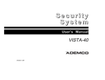
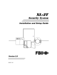
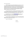
Recommendations For Smoke And Heat Detectors
With regard to the number and placement of smoke/heat detectors, we
subscribe to the recommendations contained in the National Fire
Protection Association's (NFPA) Standard #72 noted below.
Early warning fire detection is best achieved by the installation
of fire detection equipment in all rooms and areas of the
household as follows: For minimum protection a smoke detector
should be installed outside of each separate sleeping area, and
on each additional floor of a multi-floor family living unit,
including basements. The installation of smoke detectors in
kitchens, attics (finished or unfinished), or in garages is not
normally recommended.
For additional protection the NFPA recommends that you install heat
or smoke detectors in the living room, dining room, bedroom(s),
kitchen, hallway(s), attic, furnace room, utility and storage rooms,
basements and attached garages.
✪
KITCHEN
▲
DINING
✪
✪
✪
BEDROOM BEDROOM
TV ROOM
■
✪
✪
LIVING ROOM
BEDROOM
▲
KITCHEN
✪
DINING
■
LIVING ROOM
✪
■
✪
BDRM
BDRM
✪
BEDROOM
✪
▲
■ Smoke Detectors for Minimum Protection
✪ Smoke Detectors for Additional Protection
▲ Heat-Activated Detectors
■
BEDROOM
✪
■
✪
BEDROOM
TO
BR
BEDROOM
■
▲
▲
KTCHN
.
LVNG RM
■
CLOSED
DOOR
GARAGE
BASEMENT
– 45 –
Recommendations For Proper Protection (cont’d)
In addition, we recommend the following:
• Install a smoke detector inside every bedroom where a smoker
sleeps.
• Install a smoke detector inside every bedroom where someone sleeps
with the door partly or completely closed. Smoke could be blocked by
the closed door. Also, an alarm in the hallway outside may not wake
up the sleeper if the door is closed.
• Install a smoke detector inside bedrooms where electrical appliances
(such as portable heaters, air conditioners or humidifiers) are used.
• Install a smoke detector at both ends of a hallway if the hallway is
more than 40 feet (12 meters) long.
• Install smoke detectors in any room where an alarm control is
located, or in any room where alarm control connections to an AC
source or phone lines are made. If detectors are not so located, a fire
within the room could prevent the control from reporting a fire or an
intrusion.
Recommendations For Proper Intrusion Protection
For proper intrusion coverage, sensors should be located at every
possible point of entry to a home or commercial premises. This would
include any skylights that may be present, and the upper windows in
a multi-level building.
In addition, we recommend that radio backup be used in a security
system so that alarm signals can still be sent to the alarm monitoring
station in the event that the telephone lines are out of order (alarm
signals are normally sent over the phone lines, if connected to an
alarm monitoring station).
– 46 –
Emergency Evacuation
Establish and regularly practice a plan of escape in the event of fire. The following
steps are recommended by the National Fire Protection Association:
1. Position your detector or your interior and/or exterior
sounders so that they can be heard by all occupants.
PORCH
M
ET
OO
OS
DR
CL
BE
M
M
OO
OO
TH
DR
DR
BA
BE
BE
2ND FLOOR
N
HE
TC
KI
M
OO
DR
BE
BACK DOOR
M
OO
TH
DR
BA
BE
1ST FLOOR
•
•
BACK
2. Determine two means of escape from each room. One
path of escape should lead to the door that permits normal
exit from the building. The other may be a window, should
your path be impassable. Station an escape ladder at such
windows if there is a long drop to the ground.
3. Sketch a floor plan of the building. Show windows, doors,
stairs and rooftops that can be used to escape. Indicate
escape routes for each room. Keep these routes free from
obstruction and post copies of the escape routes in every
room.
4. Assure that all bedroom doors are shut while you are
asleep. This will prevent deadly smoke from entering while
you escape.
5. Try the door. If the door is hot, check your alternate
escape route. If the door is cool, open it cautiously. Be
prepared to slam the door if smoke or heat rushes in.
6. Where smoke is present, crawl on the ground; do not
walk upright. Smoke rises and may overcome you. Clearer
air is near the floor.
7. Escape quickly; don't panic.
•
FRONT
8. Establish a common meeting place outdoors, away from
your house, where everyone can meet and then take steps
to contact the authorities and account for those missing.
Choose someone to assure that nobody returns to the house
— many die going back.
– 47 –
System Testing
This control unit was manufactured under rigid quality standards and
complies with all UL requirements for its intended use. Maintenance
is best performed by your installing company with trained service
personnel.
Installing Company: ________________________________
Telephone Number: ________________________________
It is recommended that you test your system once a week using the
following procedure:
Note: If a Central Station monitors your system then contact them
prior to performing this test.
1. Arm your Security System.
2. Activate the system by opening a protected zone (example,
window, or door).
3. Confirm that the alarm sounding device (bell or siren) activates If
your system is connected to a Central Station then the keypad will
emit a ringback sound to confirm that the signal was received.
4. Disarm the system to silence the system and return to normal
status.
– 48 –
System Testing (cont’d)
Battery Test
In order to test the backup battery the following procedure should be
performed:
1. Remove the AC transformer from the AC outlet by removing the
retaining screw that secures the transformer to the wall. (Note: the
screw is not present in models sold in Canada).
2. Observe that the AC light goes off on the keypad.
3. Activate your alarm system using steps 1-4 listed above.
4. Replace the AC transformer to the AC outlet and secure using the
retaining screw (Note: The retaining screw is not present in
models sold in Canada).
The National Fire Protection Association publishes a standard for
household fire warning equipment (NFPA #74). Further information
can be obtained by contacting; NFPA Public Affairs Dept.,
Batterymarch Park, Quincy, MA 02269.
If you have any further questions about the operation of your system,
call your installer.
– 49 –
Owners Information
NAME:
_____________________________________________________________________
ADDRESS: __________________________________________________________________
CITY, STATE, ZIP: ___________________________________________________________
TELEPHONE NUMBER: _____________________________________________________
Date of Installation: __________________________________________________________
EMERGENCY NUMBERS:
CENTRAL STATION: ________________________________________________________
FIRE DEPARTMENT:
_______________________________________________________
POLICE DEPARTMENT: _____________________________________________________
NEIGHBOR: ________________________________________________________________
GAS/ELECTRIC DEPT: ______________________________________________________
DOCTOR: ___________________________________________________________________
HOSPITAL: _________________________________________________________________
EMERGENCY: ______________________________________________________________
SERVICE INFORMATION:
ALARM INSTALLING COMPANY:
– 50 –
___________________________________________
About The Manufacturer
Your new control panel and keypads are manufactured by Fire
Burglary Instruments Inc, leading manufacturer of quality reliable
security control products since 1971. Fire Burglary Instruments is a
subsidiary of Pittway Corporation. This product has been
manufactured using the latest advances in electronic and computer
technology. Thorough testing, by computer as well as quality control
experts, has occurred several times during the manufacturing process.
Fire Burglary Instruments warranties its products through your
installing company. Product reliability and ease of operation are two
of the major factors in the design of all Fire Burglary products. You
can look forward to many years of trouble free service from your
Security System.
– 51 –
Statements – Problems – Warnings
FEDERAL COMMUNICATIONS COMMISSION (FCC) STATEMENT
This equipment has been tested to FCC requirements and has been found acceptable for use. The FCC
requires the following statement for your information.
This equipment generates and uses radio frequency energy and if not installed and used properly, that is, in
strict accordance with the manufacturer's instructions may cause interference to radio and television
reception. It has been tested and found to comply with the limits of Part 15 of FCC Rules, which are
designed to provide reasonable protection against such interference in a residential installation. However,
there is no guarantee that interference will not occur in a particular installation. If this equipment does cause
interference to radio or television reception, which can be determined by turning the equipment off and on,
the user is encouraged to try to correct the interference by one or more of the following measures:
• If using an indoor antenna, have a quality outdoor antenna installed.
• Reorient the receiving antenna until interference is reduced or eliminated.
• Move the radio or television receiver away from the control/ communicator.
• Move the antenna leads away from any wire runs to the control/communicator.
• Plug the control/communicator into a different outlet so that it and the radio or television receiver are on
different branch circuits.
If necessary, the user should consult the dealer or an experienced radio/television technician for additional
suggestions. The user or installer may find the following booklet prepared by the Federal Communications
Commission helpful: "Interference Handbook". This booklet is available from the U.S. Government Printing
Office, Washington, DC 20402. Stock No. 004-000-00450-7.
The user shall not make any changes or modifications to the equipment unless authorized by the installation
Instructions or Owners Manual. Unauthorized changes or modifications could void the user's authority to
operate the equipment.
IN THE EVENT OF TELEPHONE OPERATIONAL PROBLEMS
In the event of telephone operational problems, disconnect the communicator by removing the plug from the
RJ31X jack. We recommend that the installer demonstrate disconnecting the phones on installation of the
system. Do not disconnect the phone connection inside the communicator. Doing so will result in the loss of
the phone lines. If the regular phone works correctly after the communicator has been disconnected from the
phone lines, the communicator has a problem and should be returned for repair.
If upon disconnecting the communicator, there is still a problem on your line, notify the Telephone Company
that they have a problem and request prompt repair service. The user may not under any circumstances (in
or out of warranty) attempt any service or repairs on the system. It must be returned to the factory or an
authorized service agency for all repairs.
– 52 –
Statements – Problems – Warnings (cont’d)
WARNING LIMITATIONS OF THIS ALARM SYSTEM
While this system is an advanced design security system, it does not offer guaranteed protection against
burglary, fire or other emergency. Any alarm system, whether commercial or residential, is subject to
compromise or failure to warn for a variety of reasons. For example:
• Intruders may gain access through unprotected openings or have the technical sophistication to bypass
an alarm sensor or disconnect an alarm warning device.
• Intrusion detectors (e.g., passive infrared detectors), smoke detectors, and many other sensing devices
will not work without power. Battery operated devices will not work without batteries, with dead batteries or
if the batteries are not put in properly. Devices powered solely by AC will not work if their AC power supply
is cut off for any reason, however briefly.
• Signals sent by wireless transmitters may be blocked or reflected by metal before they reach the alarm
receiver. Even if the signal path has been recently checked during a weekly test, blockage can occur if a
metal object is moved into the path.
• A user may not be able to reach a panic or emergency button quickly enough.
• While smoke detectors have played a key role in reducing residential fire deaths in the United States, they
may not activate or provide early warning for a variety of reasons in as many as 35% of all fires, according
to data published by the Federal Emergency Management Agency. Some of the reasons smoke detectors
used in conjunction with this System may not work are as follows: Smoke detectors may have been
improperly installed and positioned. Smoke detectors may not sense fires that start where smoke cannot
reach the detectors, such as in chimneys, in walls, or roofs, or on the other side of closed doors. Smoke
detectors may not sense a fire on another level of a residence or building. A second floor detector, for
example, may not sense a first floor or basement fire. Moreover, smoke detectors have sensing
limitations. No smoke detector can sense every kind of fire every time. In general, detectors may not
always warn about fires caused by carelessness and safety hazards like smoking in bed, violent
explosions, escaping gas, improper storage of flammable materials, overloaded electrical circuits, children
playing with matches, or arson. Depending on the nature of the fire and/or the location of the smoke
detectors, the detector, even if it operates as anticipated, may not provide sufficient warning to allow all
occupants to escape in time to prevent injury or death.
• Passive Infrared Motion Detectors can only detect intrusion within the designed ranges as diagramed in
their installation manual. Passive Infrared Detectors do not provide volumetric area protection. They do
create multiple beams of protection, and intrusion can only be detected in unobstructed areas covered by
the beams. They cannot detect motion or intrusion that takes place behind walls, ceilings, floors, closed
doors, glass partitions, glass doors, or window. Mechanical tampering, masking, painting, or spraying of
any material on the mirrors, windows or any part of the optical system can reduce their detection ability.
Passive Infrared Detectors sense changes in temperature; however, as the ambient temperature of the
protected area approaches the temperature range of 90 to 150F, the detection performance can
decrease.
• Alarm warning devices such as sirens, bells or horns may not alert people or wake up sleepers who are
located on the other side of closed or partly open doors. If warning devices sound on a different level of
the residence from the bedrooms, then they are less likely to waken or alert people inside the bedrooms.
Even persons who are awake may not hear the warning if the alarm is muffled by noise from a stereo,
– 53 –
Statements – Problems – Warnings (cont’d)
radio, air conditioner or other appliances, or by passing traffic. Finally, alarm warning devices, however
loud, may not warn hearing-impaired people or waken deep sleepers.
• Telephone lines needed to transmit alarm signals from a premises to a central monitoring station may be
out of service or temporarily out of service. Telephone lines are also subject to compromise by
sophisticated intruders.
• Even if the system responds to the emergency as intended, however, occupants may have insufficient
time to protect themselves from the emergency situation. In the case of a monitored alarm system,
authorities may not respond appropriately.
• This equipment, like other electrical devices, is subject to component failure. Even though this equipment
is designed to last as long as 20 years, the electronic components could fail at any time.
The most common cause of an alarm system not functioning when an intrusion or fire occurs is inadequate
maintenance. This alarm system should be tested weekly to make sure all sensors are working properly.
Installing an alarm system may make one eligible for lower insurance rates, but an alarm system is not a
substitute for insurance. Homeowners, property owners and renters should continue to act prudently in
protecting themselves and continue to insure their lives and property.
We continue to develop new and improved protection devices. Users of alarm systems owe it to themselves
and their loved ones to learn about these developments.
– 54 –
Warranty
FIRE BURGLARY INSTRUMENTS, INC. ONE YEAR LIMITED WARRANTY
Fire Burglary Instruments, Inc., a subsidiary of Pittway Corporation, and Pittway Corporation its divisions
subsidiaries and affiliates ("Seller"), 163 Eileen Way, Syosset New York 11791, warrants its security
equipment ("the product") to be free from defects in materials and workmanship for one year from the date
of original purchase, under normal use and service. Seller's obligation is limited to repairing or replacing, at
its option, free of charge for parts, labor, or transportation, any product proven to be defective in materials or
workmanship under normal use and service. Seller shall have no obligation under this warranty or otherwise
if the product is altered or improperly repaired or serviced by anyone other than Seller. In case of defect,
contact the security professional who installed and maintains your security equipment or the Seller for
product repair.
This one year Limited Warranty is in lieu of all other express warranties, obligations or liabilities. THERE
ARE NO EXPRESS WARRANTIES, WHICH EXTEND BEYOND THE FACE HEREOF. ANY IMPLIED
WARRANTIES, OBLIGATIONS OR LIABILITIES MADE BY SELLER IN CONNECTION WITH THIS
PRODUCT, INCLUDING ANY IMPLIED WARRANTY OF MERCHANTABILITY, OR FITNESS FOR A
PARTICULAR PURPOSE OR OTHERWISE, ARE LIMITED IN DURATION TO A PERIOD OF ONE YEAR
FROM THE DATE OF ORIGINAL PURCHASE. ANY ACTION FOR BREACH OF ANY WARRANTY,
INCLUDING BUT NOT LIMITED TO ANY IMPLIED WARRANTY OF MERCHANTABILITY, MUST BE
BROUGHT WITHIN 18 MONTHS FROM DATE OF ORIGINAL PURCHASE. IN NO CASE SHALL SELLER
BE LIABLE TO ANYONE FOR ANY CONSEQUENTIAL OR INCIDENTAL DAMAGES FOR BREACH OF
THIS OR ANY OTHER WARRANTY, EXPRESS OR IMPLIED, OR UPON ANY OTHER BASIS OF
LIABILITY WHATSOEVER, EVEN IF THE LOSS OR DAMAGE IS CAUSED BY THE SELLER'S OWN
NEGLIGENCE OR FAULT.
Some states do not allow limitation on how long an implied warranty lasts or the exclusion or limitation of
incidental or consequential damages, so the above limitation or exclusion may not apply to you. Seller does
not represent that the product may not be compromised or circumvented; that the product will prevent any
personal injury or property loss by burglary, robbery, fire or otherwise; or that the product will in all cases
provide adequate warning or protection. Buyer understands that a properly installed and maintained alarm
may only reduce the risk of a burglary, robbery, or fire or other events occurring without providing an alarm,
but it is not insurance or a guarantee that such will not occur or that there will be no personal injury or
property loss as a result. CONSEQUENTLY, SELLER SHALL HAVE NO LIABILITY FOR ANY PERSONAL
INJURY, PROPERTY DAMAGE OR OTHER LOSS BASED ON A CLAIM THE PRODUCT FAILED TO
GIVE WARNING. HOWEVER, IF SELLER IS HELD LIABLE, WHETHER DIRECTLY OR INDIRECTLY,
FOR ANY LOSS OR DAMAGE ARISING UNDER THIS LIMITED WARRANTY OR OTHERWISE,
REGARDLESS OF CAUSE OR ORIGIN, SELLER'S MAXIMUM LIABILITY SHALL NOT IN ANY CASE
EXCEED THE PURCHASE PRICE OF THE PRODUCT, WHICH SHALL BE THE COMPLETE AND
EXCLUSIVE REMEDY AGAINST SELLER. This warranty gives you specific legal rights, and you may also
have other rights which vary from state to state. No increase or alteration, written or verbal, of the obligations
of this Limited Warranty is authorized.
– 55 –
Subsidiary of Pittway Corp.
149 Eileen Way, Syosset, New York 11791
Copyright © 1998 PITTWAY CORPORATION
¬1l
N9144-1 10-98