1
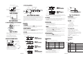
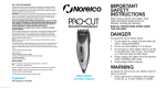
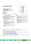
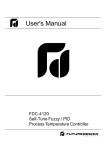
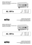
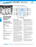
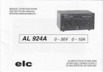
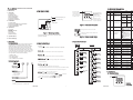
NC200 User's Manual
1.6 Parameter Descriptions
CONTENTS
1. Overview
Register Parameter Parameter Description
Address Notation
1.3 Mini-jumper Setting
1.1 Introduction
1.2 Ordering Code
1.3 Mini-jumper Setting
1.4 Keys and Displays
1.5 Operation Flowchart
1.6 Parameter Descriptions
Dual-color LED
Green color indicates
control output on
Red color indicates
an alarm occurs
: Thermocouple Input (J, K)
Three-digit display, to
display process value,
menu symbol,
parameter value
and error message
etc.
+
2.1 Product Views
2.2 Connecting NC200 to Power and Heater
2.3 Connecting NC200 to Sensor
2.4 Networking NC200'S
Set point value for
control
SP1
Mini jumper
1
High alarm set point
ALH
Low: 25 LC
(77.0 LF)
High:500 LC
(932.0 LF)
ALF=P.Hi,
P.Lo, P.HL
2
ALL
3
IN
Low alarm set point
Figure 2 Front Panel Description
3. Operation
Low: -17.8 LC
(0 LF)
ALF=P.Hi,
P.Lo, P.HL
3 Buttons for ease
of control setup and
set point adjustment.
: RTD Input (PT100)
2. Installation
0
Range
All segments are lit for 2.3 seconds
Figure 1 Mini-jumper setting
Display the software release number for
2.5 seconds.
The mini-jumper on the PCB is used to select the sensor
type for the controller.
4. Specifications
1.4 Keys and Displays
Home page
Scroll key :
This key is used to select a parameter to be viewed or adjusted.
Setup page
and
4sec.
PV
Up key :
This key is used to increase the value of selected parameter.
Value
or
Value
or
Value
and
Reset key:
This key is used to:
1. Revert the display to indicate the process value.
2. Stop the manual control mode, auto-tuning mode and calibration mode.
3. Clear the message of communication error and auto-tuning error.
Signal Input
1: Standard Input
Thermocouple: J, K
RTD: PT100DIN
9: Special Order
Enter key: Press
for 4 seconds or longer to :
1. Enter setup page. The display shows
.
2. Enter manual control mode during output value
3. Enter auto-tuning mode during
is selected.
Control Output
Press
3. Solid State Relay, 3A/250VAC
6
PB
Proportional band
value
4sec.
4sec.
is selected.
Auto-tuning
Mode
:J type thermocouple
-10 BC
(-18BF) R/W
R/W
5
R/W
:Deviation high/low
alarm
Low: -100 LC High:100 LC
(-180LF)
(180LF)
0 BC
(0 BF)
R/W
Low: 1 LC
(2 LF)
High:500 LC
(900.0 LF)
10 BC
(18 BF) R/W
100
R/W
25
R/W
100%
R/W
:K type thermocouple
:PT 100 ohms (DIN)
0.
:Process high alarm
1.
:Process low alarm
2.
3.
:Process high/low
alarm
:Deviation high alarm
4.
:Deviation low alarm
7
TI
Integral time value
Low: 1
High:900 sec
TD
Derivative time value
Low: 0
High:300.0 sec
9
PL
Power limit
Low: 0 %
High:100%
10
ADL
Voltage calibration low Low: -1999
coefficient
11
ADH
Voltage calibration
high coefficient
Low: -1999
High:1999
R/W
12
RDL
RTD calibration low
coefficient
Low: -1999
High:1999
R/W
13
RDH
RTD calibration high
coefficient
Low: -1999
High:1999
R/W
14
CJL
Low: -1999
High:1999
R/W
15
CJH
Cold junction
calibration low
coefficient
Cold junction
calibration high
coefficient
Low: -1999
High:1999
R/W
or
17
COD
Security code
Low: 1
High:900
Value
20
PV
Process value
Low: -17 LC
(0 LF)
High:500 LC
(932 LF)
R
Set point value
Low: -17 LC
(0 LF)
High:500 LC
(932 LF)
R
21
Manual
Mode
R/W
ALF=D.Hi,
D.Lo, D.HL
8
or
NC200-
4: 90 ~ 250 VAC,
47 ~ 63 HZ
PV shift (offset) value
or
Value
Power Input
SHI
Value
and
Address key:
Press both scroll key and down key to display the communication
address of the unit.
1.2 Ordering Code
6sec.
5
or
Down key :
This key is used to decrease the value of selected parameter.
* COMPACT SIZE
* EASY INSTALLATION
* SELF ADDRESSING
* FAST COMMUNICATION SPEED
Alarm function for
alarm output
10 BC
Low: 5 LC
(18BF)
(9.0 LF)
High:40.0 LC
(72.0 LF)
5.
1.5 Operation Flowchart
The NC200 is a compact fuzzy logic plus PID temperature
controller with J or K type thermocouple or RTD input.
Multiple units (up to 247 units) can be networked together
with 4P4C modular connector. Each unit auto-tunes on
initial setup to provide the best response for each heater.
The NC200 is powered by 90-250VAC supply and contains
a solid state relay as its control output. The solid state relay
can drive the heater directly through a plug-in connector.
The major features of the unit are as following:
ALF
Figure 3 Display of Initial Stage
5. Error Message
1. Overview
1.1 Introduction
4
ALF=D.Hi,
D.Lo, D.HL
LF : 0
LC : 1
2.
3.1 Lockout
3.2 Display Address
3.3 Alarm
3.4 PV Shift
3.5 Auto-tuning
3.6 Manual Control
Data
Type
High:500 LC 25 BC
(932 LF) (77 BF) R/W
Low: 0 LC
Low: -40 LC
(32.0 LF)
(-72.0 LF)
High:ALH-5 LC High:-5 LC
(ALH-9.0 LF)
(-9.0 LF)
0.
Input sensor selection 1.
Default
Value
or
SV
High:1999
R/W
666
R/W
22
MV
Control output value
Low: 0
High:100%
R
23
STA
Status word
Low: 0
High:527
R
Value
or
Value
2. Installation
2.1 Product Views
or
Value
Status
Indicator
for 6 seconds will display the process value.
or
Options
Value
0: LC
1: LF
Figure 4
Front View
Standard ordering code = NC200-4130
UMNC200B
1
UMNC200B
2
Sensor Type selection
2.4 Networking NC200's
Sensor
Lead Port
PV
SP1
SP1+ALL
Figure 14
Deviation Low Alarm
Figure 5 Left Side View
NO C
RJ11
R
N
L
CAT. II
RS-232 Port
90-264VAC
47-63HZ 10VA
Opening for Mounting Tape
PWR(G)
From
HMI or
PC
Connects to
Next NC200
1'st
NC200
2'nd
NC200
Power
Opening for Mounting Tape
Figure 6 Right Side View
Figure 9 shows the proper direction to install the RJ11 4P4C communication
cable. The first unit is connected from the Data Logger DL200 to its
communication input port (Left Side)which is at same side of the sensor input
port. The first unit is connected its communication output port (Right Side) to
the communication input port of the second unit.
Each unit is connected its communication output port to the communication
input port of next unit. The last unit leaves the communication output port
open.
3.1 Lockout
The parameter CODE (displayed as
) provides a security code for
up-down key operation. If and only if the value of CODE is adjusted to be
equal to 666, the up-down key functions are enabled.
3.2 Display Address
PIN NO. 1
When you press both scroll key and down key the value of address of the unit
will be shown on the display. Exception case: If the displayed value is equal
to zero, it indicates that the network linkage is abnormal.
PIN NO. 2
Figure 7 Power Wiring
3.3 Alarm
Pin No.1: to Ground
Pin No.2: to Neutral Lead of Power Input
Pin No.3: to Line Lead of Power Input and One Lead of
Heater
Pin No.4: to Another Lead of Heater
Receptacle Housing: Use ALEX 9357-4
Crimp Terminal: Use ALEX 4256T series
The controller has 6 alarm functions and when one of alarm functions occurs,
the LED indicator will show red color. The alarm functions are described as
following Figure:
PV
ALH
Figure 10
Process High Alarm
2.3 Connecting NC200 to Sensor
Receptacle Housing
with Crimp Terminal
ALL
Data Communication
3.4 PV Shift
Interface: Differential driver/receiver
Protocol: Proprietary Protocol
Baud Rate: 92.16 K bits/sec.
In certain applications it is desirable to shift the controller display value from
its actual value. This can be easily accomplished by using the PV
shift function.
For example, the default value of SHI is zero. Now if PV is equal to 100(LC),
and SHI is changed to 20, then PV will be changed to 120 (LC).
Control Mode
Action Reverse (heating)
PID mode:
Figure 11
Process Low Alarm
ALH
ALL
Figure 12
Process High/Low
Alarm
Power up
Approval standards
Safety: EN61010-1
4. Specifications
UMNC200B
Protective class: IP20
EMC: EN61326
Input
Type
Range
-17.8 LC ~ 500 LC
(932 LF)
(0 LF)
Accuracy
Input Impedance
K 2 LC
1 MW
K
-17.8 LC ~ 500 LC
(932 LF)
(0 LF)
K 2 LC
1 MW
PT100
(DIN)
-17.8 LC ~ 500 LC
(932 LF)
(0 LF)
K 1 LC
1.3 KW
5. Error Message
Display
symbol
Figure 13
Deviation High Alarm
3
Error Description
Solution
Hardware failure
Return to factory for repair
occurs
Sensor break
Replace input sensor
occurs
Cold junction error Return to factory for repair
occurs
1. Never change set point
value during auto-tuning
Auto-tuning
procedure.
procedure fails
2. Retry auto-tuning.
Output (Solid state relay)
PV
SP1
Operating temperature: -10LC ~ 50LC
Storage temperature: -40LC ~ 60LC
Humidity: 0 ~ 90%RH (non-condensing)
Altitude: 2000 m maximum
Insulation resistance: 20 Mohms min. (at 500VDC)
Dielectric strength: 1350VAC, 50/60 Hz for 1 minute
Vibration resistance: 10-55 Hz, 10 m/s 2 for 2 hours
Shock resistance: 200 m/s 2 (20g)
Dimensions:
NC200 ----------- 50.3(W) x 52.4(L) x 45(H)
Weight ----------- 112 grams
Press the scroll key until
appears on the display. Now the display
indicates the percentage value of control output.
Press the scroll key for 4 seconds, the display value will begin to flash and
control output value can be changed by up and down keys.
PV
SP1+ALH
Environmental & Physical
3.6 Manual Control
J
The Polarity + of Sensor Lead should be
connected to the left side of Sensor
Lead Port.
Receptacle Housing: Use ALEX 9566-02 G
Crimp Terminal: Use ALEX 9558-TP
PB= 1-500 LC
TI= 1-900 sec.
TD= 0-300 sec.
Cycle time: 2 seconds
Manual control: 0-100%
Auto-tuning: Cold start and warm start
Power limit: 0-100%
Operation:
(1) The system has been installed normally.
(2) Set the point to a normal operating value or a lower value if overshooting
beyond the normal process value is likely to cause damage.
(3) Press scroll key until
appears on the display.
(4) Press scroll key for 4 seconds, the display value will begin to flash and
auto-tuning procedure is beginning.
(5) After the PID auto-tuning cycle completes, the PID constant values are
saved inside of the unit and the display ceases to flash.
Sensor Lead
Figure 8 Sensor Wring
47.5 LC 70 LC
Figure 16 Load Derating Curve
Please note when the process high/low or deviation high/low is selected for
alarm function, the alarm is disabled during the power up stage and the alarm
is enabled until the process value enters the high/low band.
Power
90 ~ 250 VAC, 47 ~ 63 Hz, 800VA maximum
PV
+
25LC
Ambient temperature
The auto-tuning is applied in cases of :
(1) Initial setup for a new process.
(2) The set point is changed substantially from the previous auto-tuning value.
(3) The control result is unsatisfactory.
3. Operation
Receptacle Housing
with Crimp Terminal
3.5A
0A
3.5 Auto-tuning
2.2 Connecting NC200 to Power and Heater
PIN NO. 4
PIN NO. 3
Figure 15
Deviation High/Low
Alarm
7A
Power up
Figure 9 Communication installation
Communication
Output Port
PV
SP1+ALH
SP1
SP1+ALL
T
RS-232
Communication
Input Port
AL(R)
Power &
Heater Port
DL200
DL200
Load current
RJ11 4P4C Cable
Rating : 7A @25LC, 3.5A @47.5LC ambient temperature,
90 ~ 250 VAC, 47 ~ 63Hz.
See Fig.16 Load derating curve
Switch ON-OFF: Zero crossing triggering
Insulation resistance: 1000 Mohms min. at 500 VDC
Dielectric strength: 2500 VAC for 1 minute.
UMNC200B
4