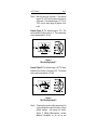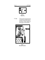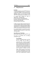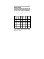
1
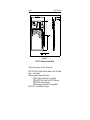
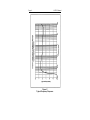
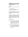
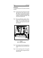
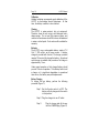
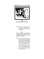
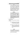
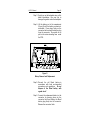
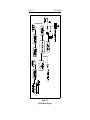
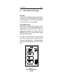
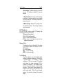
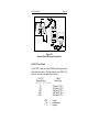
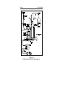
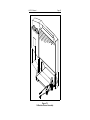
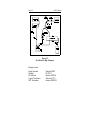
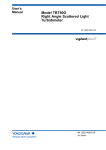
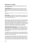
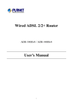
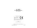
HI-3701
Induced Current Meter
User's Manual
Copyright
© 1996 Holaday Ind. Inc.
Manual #600048 03/96
$12.50
Revision Record
Manual # 600048
HI-3701
Induced Current Meter
Revision
--A
B
C
Description
Preliminary Release
Release
Battery charger change
Updated sensor
Date
9/92
4/93
12/94
3/96
TABLE OF CONTENTS
Section 1 -- Product Overview . . . . . . . . . . . . . .
1
Introduction . . . . . . . . . . . . . . . . . . . . . . . 1
Specifications . . . . . . . . . . . . . . . . . . . . . . 3
Section 2 -- Operating the HI-3701 . . . . . .
Introduction . . . . . . . . . . . . . . . . .
Unpacking and Acceptance . . . . . . .
Getting Started . . . . . . . . . . . . . . .
Controls, Indicators, and Connectors
.
.
.
.
.
.
.
.
.
.
.
.
.
.
.
.
.
.
.
.
.
.
.
.
.
Section 3 -- Making Measurements . . . . . .
Introduction . . . . . . . . . . . . . . . . .
Generic Measurement Considerations
Measurement Technique . . . . . . . . .
Heat Sealer Application Example . . .
Antenna Farm Application Example .
.
.
.
.
.
.
.
.
.
.
.
.
.
.
.
.
.
.
.
.
.
.
.
.
. 11
. 11
. 11
13
. 14
. 14
.
.
.
.
.
.
.
.
.
.
.
.
.
.
.
.
.
.
.
.
.
.
.
.
.
.
.
.
.
.
.
.
.
.
.
.
.
.
.
.
.
.
.
.
.
Section 4 -- Maintaining the HI-3701
Introduction . . . . . . . . . . . .
Calibration . . . . . . . . . . . . .
Cleaning . . . . . . . . . . . . . . .
Batteries . . . . . . . . . . . . . . .
Battery Charging . . . . .
Battery Replacement . .
Replacement Parts . . . . . . . .
Options . . . . . . . . . . . . . . .
.
.
.
.
.
.
.
.
.
.
.
.
.
.
.
.
.
.
.
.
.
.
.
.
.
.
.
.
.
.
.
.
.
.
.
.
.
.
.
.
.
.
.
.
.
.
.
.
.
.
5
5
5
6
8
15
15
16
16
16
16
18
20
20
Section 5 -- Principles of Operation . . . . . . . . . . . 21
Introduction . . . . . . . . . . . . . . . . . . . . . . 21
Meter Theory . . . . . . . . . . . . . . . . . . . . . 21
Section 6 -- Remote Readouts and Data Logging
Introduction . . . . . . . . . . . . . . . . . . . .
HI-3715 Remote Readout . . . . . . . . . . .
HI-3715 Indicators . . . . . . . . . . . . . . . .
Data Logging . . . . . . . . . . . . . . . . . . .
HI-3701 Data Format . . . . . . . . . . . . .
.
.
.
.
.
.
.
.
.
.
.
.
23
23
23
25
26
27
Appendix A -- HI-3701 Calibration Methods . . . . . 29
LIMITED WARRANTY
Holaday Industries, Inc. warrants each Model HI-3701 Induced
Current Meter to be free from defects in material and workmanship
for a period of one year from date of shipment to the purchaser.
This warranty extends to the original purchaser only and does not
apply to batteries or any product or parts subject to misuse,
neglect, accident, unauthorized service or abnormal conditions of
operation.
In the event of instrument failure covered by this warranty,
Holaday Industries, Inc. will, without charge, repair and recalibrate
the instrument if returned to their factory within one year of the
original purchase, provided that Holaday Industries' examination
discloses to its satisfaction that the product was defective.
Holaday Industries, Inc may, at its option, replace the product in
lieu of repair. If the defect was caused by misuse, neglect,
accident, unauthorized service or abnormal conditions of
operations, repairs will be billed at a nominal cost. In such case, an
estimate will be provided before work is started if requested by the
purchaser.
For warranty service, contact Holaday Industries, Inc., giving full
details of the failure and the serial number of the instrument. You
will then be given service information or shipping instructions.
Return the instrument to the factory, transportation prepaid.
Repairs will be made at the factory and the instrument returned to
you, transportation paid. Holaday Industries, Inc. assumes no
responsibility for loss of, or damage to, products in transit.
!! WARNING !!
Special caution is advised when working in environments where
contact with high voltage or high current circuits or apparatus is
possible. This is particularly true when attempting to obtain
induced body current measurements near electrically-powered
equipment, such as heat sealers, or in areas marked with warnings
about the presence of high voltages, currents, or RF fields.
Accidental contact with objects, circuits, or fields operated at high
voltages or high current can be lethal! Holaday Industries, Inc.
assumes no liability for damages or personal injury which may
result from accidents arising out of the use of this equipment.
HI-3701 Manual
1.0
Page 1
Product Overview
Introduction
The HI-3701 Induced Current Meter measures the
induced body current of individuals working in
environments where radio frequency (RF) electromagnetic
fields are present.
The Institute of Electrical and
Electronics Engineers (IEEE) specification C95.1-1991,
IEEE Standard for Safety Levels with Respect to Human
Exposure to Radio Frequency Electromagnetic Fields, 3
kHz to 300 GHz, defines the acceptable levels of RFinduced body current for the frequency range of 3 kHz to
100 MHz. The acceptable levels range from 3 mA for
uncontrolled exposures at 3 kHz to 200 mA for controlled
exposures between 100 kHz and 100 MHz.
The HI-3701 is designed to meet the requirements of
C95.1-1991. The accuracy of this instrument provides a
means for determining compliance. The unit is completely
portable and self-contained. Simple to set up and easy to
operate, the HI-3701's rugged design can be used for
measurements in applications environments such as:
! Induction heating facilities
! Industrial welding applications
! Broadcast transmitting and antenna locations
The Model HI-3701 includes as standard the following
items:
! Model HI-3701 Meter
! Battery Charger (15 hr. charge cycle)
! User's Manual
! Soft-sided Carrying Case
Page 2
HI-3701 Manual
Figure 1
HI-3701 Induced Current Meter
Optional accessories for the unit include:
! HI-3715 Fiber Optic Remote Readout Unit (includes
fiber
optic cable)
! Data Logging Computer Interface
# Fiber Optic Cable (glass, 4 m length)
# HI-4413P Fiber Optic to RS-232 Interface
# RS-232C Cable Assembly
# Data Logging Software (PC compatible)
! HI-3102 1-Hour Battery Charger
HI-3701 Manual
Page 3
Specifications
Ranges: 10, 30, 100, 300, 1000 mA full scale
Frequency Response: 3 kHz to 100 MHz
± 1.0 dB (3 kHz to 30 MHz)
± 2.0 dB (30 MHz to 100 MHz)
(See Figure 2)
Battery: NiCad Rechargeable
7.2V / 1,300 mA-hrs
Battery Charger: 15 Hour charge cycle time
Battery Life:
Dimensions:
Approx. 12 hrs. of operation/charge
360 x 485 x 50mm (14 x 19 x 2 in.)
Weight: 6.2 kg (14 lb.)
Page 4
HI-3701 Manual
Figure 2
Typical Frequency Response
HI-3701 Manual
Page 5
2.0 Operating the HI-3701
Introduction
The operation of the HI-3701 consists of three main
steps:
1.
2.
3.
Verifying battery condition
Turning the unit on and setting the desired range
Making the necessary measurements
These steps are described in detail in the "Getting
Started" procedure provided below. This section also
contains descriptions of the HI-3701's switches, controls
and indicators.
If you are using optional equipment such as the HI-3715
Remote Readout or a remote data logger, information on
using those options is found in Section 6, Remote
Readout and Data Logging. Measurement considerations
and examples are provided in Section 3, Making
Measurements.
Unpacking and Acceptance
Step 1. Remove the meter from its shipping container.
Save the boxes and any protective packing
materials for future use. Inspect the HI-3701 for
concealed damage incurred in transit. If any
damage is found, file a claim with the carrier.
Step 2. Verify that the materials you received are the
same as you ordered and correspond with the
packing list. If you find discrepancies, note
them and call Holaday Customer Service for
further directions.
Page 6
HI-3701 Manual
Getting Started
To get started using the HI-3701 perform the following
procedure:
Step 1. Set the rotary Function switch (Figure 3) to BAT
and verify that the meter reads in the green
BAT. OK area. (If the meter reads to the left of
the green area, the batteries require recharging.
See Section 4, Maintaining the HI-3701). Then
set the Function switch to OFF.
Step 2. With an acceptable battery indication in Step 1,
place the unit in the desired location for the
reading. (If you are using any fiber optic
accessories connect those units into their fiber
optic connector).
Figure 3
HI-3701 Component Locations
Step 3. Have the subject stand or sit (as appropriate) on
the unit metal plate, and set the Function switch
to ON.
Step 4. Set the rotary Range switch to the range that
gives a meter indication from approximately midscale to full scale.
HI-3701 Manual
Page 7
Step 5. Read the value from the meter. If the selected
range is 30 or 300 use the values along the top
of the scale. If the selected range is 10, 100, or
1000, use the values along the bottom of the
scale.
Example (Figure 4): The selected range is 100. The
meter indication (bottom scale) is .8. The induced body
current measurement is 80 mA.
Figure 4
Meter Reading Example 1
Example (Figure 5): The selected range is 30. The meter
indication (from the top of the scale) is 2.5. The induced
body current measurement is 25 mA.
Figure 5
Meter Reading Example 2
Step 6. To improve the accuracy of the measurement for
a given individual in a specific location, perform
multiple readings and average the results.
Section 3, Making Measurements, contains
additional information on the set up and
Page 8
HI-3701 Manual
repetition of measurements.
Step 7. When the measurements are complete, set the
Function switch to OFF and disconnect any
accessories.
Controls, Indicators, and Connectors
The HI-3701 has the following controls, indicators, and
connectors:
Function Switch
A three-position rotary switch that
selects the operational function for the
HI-3701.
OFF
Removes power from the unit. The
function switch must be in this position
for the battery charger to charge the
battery.
BAT
Used for testing the battery. With the
switch in this position, the meter
indicates above the green BAT.OK line
if the meter is usable. Any other
indication means that the battery
requires recharging.
ON
Normal operating position. Switch must
be in this position for performing
measurements.
HI-3701 Manual
Range Switch
Page 9
A five-position rotary switch that
selects the value range for the induced
current being measured.
10
Indicates a reading in the range of 10
mA or less. Use the bottom scale on
the meter to determine the exact value.
30
Indicates a reading in the range of 30
mA or less. Use the top scale to
determine the exact value.
100
Indicates a reading in the range of 100
mA or less. Use the bottom scale on
the meter to determine the exact value.
300
Indicates a reading in the range of 300
mA or less. Use the top scale on the
meter to determine the exact value.
1000
Indicates a reading in the range of
1000 mA or less. Use the bottom
scale on the meter to determine the
exact value.
Current Meter
Charge Jack
A dual-scale meter that indicates
induced body current in five ranges
from 10 mA to 1000 mA. The meter
also indicates battery condition with
the Function switch in the BAT
position.
The charger jack is used for connecting
the battery charger to the HI-3701. To
charge the battery, ensure that the
Function switch is in the OFF position
and insert the charger plug (Figure 6)
into the jack. In any other switch
position, the battery will not charge.
Page 10
HI-3701 Manual
Figure 6
Charger Plug
F.O. Jack
This jack receives the plug on the fiber
optic cable that connects the fiber optic
accessories to the HI-3701 (Figure 7).
See Section 6, Remote Readout and
Data Logging for more information.
Figure 7
Fiber Optic Connection
HI-3701 Manual
3.0
Page 11
Making Measurements
Introduction
Successful measurements using the HI-3701 depend on
a well-planned measurement series as well as proper
operation of the HI–3701. For the HI-3701 data to be
meaningful, especially within the definitions of IEEE
C95.1-1991, several measurement considerations should
be examined before beginning any series of
measurements. The factors include:
! Type and intensity of RF-generating device
! Location of personnel throughout the work cycle
! Environmental characteristics
! Surveyor's effects on the RF field
In addition, the unique qualities of each measurement site
will require additional examination before conducting a
measurement series. Providing specific details for making
measurements for every kind of application in which the
HI-3701 may be used is beyond the scope of this manual.
Every individual installation or work site will have specific
features that must be accounted for to get the most
useful data possible.
Generic Measurement Considerations
Before making a measurement with the HI-3701, study
the area to be measured with the following
considerations in mind:
Type of RF Device
The type of RF-generating device may affect
both the location and the number of
measurements made. A relatively constant RF
field in an antenna farm will require a different
series of measurements than those taken in a
heat seal work cell. With the heat sealer, the
intensity of the RF field and its distribution may
vary with how the device operates in the work
cycle, the presence of conductors, and other
factors. With an awareness of how and when
the RF field is being generated, you can take
measurements at the right time and in the right
place to give a complete picture of personnel
Page 12
HI-3701 Manual
exposures.
Location of Workers
Before starting to take measurements, watch the
person or persons to be measured go through an
entire work cycle. Note the following things:
! Are they standing or sitting?
! How close are they to the RF source?
! Do they move about during the course of a
work
cycle
The answers to these questions may suggest,
for example, taking readings at locations within
the work space in addition to the chair or place
where the person works most of the time.
Environmental Characteristics
Environmental characteristics include such things
as the composition of the floor (wood, concrete,
concrete with metal rebar) or the presence of
conductive materials (metal storage shelves or
structural members). These characteristics may
suggest taking additional measurements at a
wider range of locations within the work space.
Personnel and Apparel
Even in the same location and environment,
individuals of different body size may provide
different induced current measurements.
Likewise, the type of shoes, clothing, and (in
some cases) accessories such as rings and
jewelry can influence measurements. These
considerations
may
suggest
taking
measurements of personnel during all shifts to
get a complete range of readings.
Surveyor's Effects
If the person using the HI-3701 stands near the
person being measured, the measurement can be
affected. To minimize these effects have the
person being measured call out the reading or
use an HI–3715 Remote Readout.
HI-3701 Manual
Page 13
Measurement Technique
To get the most reliable measurement data possible, take
at least three measurements at each physical location and
work cycle time point. Average the measurements to
arrive at a final measurement. The sample table provided
below shows how you might create a form to support
such a measurement technique.
Worker
Location/
Cycle
Time
Read.
#1
Read.
#2
Read.
#3
Average
For other measurement techniques see Section 6, Remote
Readout and Data Logging.
Page 14
HI-3701 Manual
Heat Sealer Application Example
A floor plan for a heat sealing work station may contain
several chairs on which the workers sit. It may also have
metal stacking trays for placing finished goods. The fact
that the workers will be both sitting and standing during
their work cycle suggests the need for standing
measurements near the heat sealing units as well as near
the conductive metal stacking trays. It also suggests that
workers may be exposed to RF when others are using the
sealer. That means taking measurements throughout a
complete work cycle, whether the individual being
measured is using (or near) the heat sealer or not.
Antenna Farm Application Example
Maintenance and other personnel working in the vicinity
of antenna farms, such as those for radio and television
transmitters, also experience RF induced body current.
Here, specific factors affecting the measurements include
the frequency and power of the transmitter, the
characteristics (including grounding) of the antenna
system, and the location of the personnel -- in the
transmitter or station area, on the grounds, or up in the
tower. For outside measurements, dampness or dryness
may have an impact, so measurements after a rain as
well as during a dry period may be called for. When
making measurements in this environment, exercise
caution about measuring near the antenna or marked
danger areas while the transmitter is operating at full
power (see Warning on Warranty Page). Record the
transmitter output power when any measurement is
taken.
HI-3701 Manual
4.0
Page 15
Maintaining the HI-3701
Introduction
Maintaining the HI-3701 requires that the Nicad batteries
be properly charged and that the battery condition be
monitored.
Under normal operating conditions,
recharging the rechargeable battery is the only
recommended user-performed maintenance. The normal
operational life (approximately 1,000 charge/discharge
cycles) of the battery is such that by the time the
batteries need replacement, the HI-3701 will probably
also need recalibration. These tasks are performed by the
Holaday Service Department.
In cases of accidental damage to the battery that causes
premature failure, it is possible to replace the pack in the
field. A procedure and replacement battery part number
are provided in this section.
Calibration and all other maintenance tasks should be
performed by Holaday Industries, Inc. service personnel.
Contact the Holaday Service Department to receive return
authorization and shipping instructions if you need to
return your unit to the factory for maintenance work.
CAUTION
Except for replacement of a prematurely
failed battery, there is no reason for
users to open the HI-3701. Be aware
that removing the unit back panel may
invalidate your warranty.
Page 16
HI-3701 Manual
Calibration
Holaday Industries recommends yearly calibration of the
HI-3701 by the Holaday Service Department. At that
time, the battery condition is also checked.
Cleaning
The HI-3701 is water-resistant, but not waterproof.
Therefore, clean the unit using a mild detergent and a
damp sponge. Do not use high pressure sprays, and
under no circumstances should the unit ever be immersed
in water or other liquids. Such actions will invalidate the
warranty.
Batteries
The HI-3701 uses a rechargeable battery, rated at 7.2
Vdc / 1,300 mA-hrs. as its power source. A battery
charger is provided with the unit. The charger provided
requires 15 hours to fully charge the battery. An optional
quick charger is available that provides a full charge in
approximately 1 hour.
Under normal operation, a fully charged battery should
provide 12 hours of operation. If the battery fails to hold
a charge, or if a significant degradation in operational
time occurs, the battery may need replacement.
Battery Charging
To charge the low battery, perform the following
procedure (Figure 7):
Step 1. Set the Function switch to OFF. The
battery will only charge with the switch
in this position.
Step 2. Plug the charger into an AC outlet.
Step 3.
Plug the charger jack all the way
into the CHARGE plug (Figure 8).
HI-3701 Manual
Page 17
Figure 8
Plug and Switch Settings for Recharging
Step 4. Verify that the green light on the
charger unit is lit, indicating that the
unit is charging. Allow 15 hours for a
full charge cycle.
Note
Charging the battery up to approximately 24
hours will not harm the battery pack. However,
charging the pack longer than 24 hours could
degrade battery performance.
Step 5. At the completion of the charge cycle,
remove the charger plug from the
CHARGE jack and unplug the charger
from the AC outlet. Set the Function
Switch to BAT and verify that the meter
reads above the green BAT.OK zone. If
it does, proceed with normal use of the
HI-3701. If the meter does not read
above the green BAT. OK line, the
battery is no longer holding a charge
and needs replacement.
Page 18
HI-3701 Manual
Note
If the battery has been through its normal life
span of approximately 1,000 charge/discharge
cycles, return the HI-3701 to Holaday Industries
for battery replacement and recalibration. If the
battery has prematurely malfunctioned and you
wish to replace the battery yourself, contact the
Holaday Service Department to order a
replacement battery pack. Then perform the
following battery replacement procedure.
WARNING !!
When disposing of Nicad batteries, be sure to
follow the applicable environmental guidelines in
your locality for disposal of heavy metal products
such as Nicad batteries.
Under no
circumstances should the HI-3701 battery be
disposed of with regular trash. If you are unsure
of battery disposal regulations in your location,
you can return your old Nicad battery pack to
Holaday for disposal.
Battery Replacement
To replace the HI-3701 battery, perform the following
procedure:
Step 1. Verify that you are using a Holaday
battery (P/N 491048) or an equivalent
7.2 V @ 1,300 mA hrs. Nicad battery.
Step 2. Remove the 19 screws from the
perimeter of the metal plate which
covers the top half of the back side of
the unit (directly behind the controls and
meter).
CAUTION
While the backplate is removed do not touch any
of the potentiometers or other components on
the exposed printed circuit board (PCB). Such
contact could cause miscalibration.
HI-3701 Manual
Page 19
Step 3. Gently pry up the backplate using a flatblade screwdriver. Use care not to
damage the gasket under the backplate.
Step 4. Lift the battery out of its compartment
(Figure 9) until the battery connector is
accessible. Press down firmly on the
connector latch and pull the battery plug
from the connector. Be careful not to
pull on the wires extending from under
the PCB.
Figure 9
Battery Removal and Replacement
Step 5. Discard the old Nicad battery in
accordance with local environmental
procedures and regulations. Do not
dispose of the Nicad battery with
regular trash!
Step 6. Connect the replacement battery to the
connector by pressing down on the
connector latch and sliding the Nicad
battery plug firmly into the connector.
Release the connector latch.
Page 20
HI-3701 Manual
Step 7. Seat the battery in its compartment.
Carefully tuck the connector and its
wiring under the PCB so that no
scraping or damage occurs to the PCB.
Ensure that the battery wires are not
pinched or crimped when the backplate
is replaced.
Step 8. Reseat the gasket making sure that it is
properly positioned so that all screw
insert holes are accessible.
Then
reposition the backplate and fasten it
down using all of the screws.
Replacement Parts
Replacement parts for the HI-3701 can
the following Holaday part numbers:
Nicad Battery (7.2 V)
Nicad Battery Charger (7.2 V)
3701 Softside Carrying Case
HI-3701 Induced Current Meter
User's Manual
be ordered using
491048
491063-01
51560028
600048
Options
Optional equipment for the HI-3701 can be ordered using
the following Holaday part numbers:
Fiber Optic Remote Readout
(including fiber optic cable)
1 Hour Battery Charger
Fiber Optic to RS232 Interface
Fiber Optic Cable (4 m)
RS-232 Cable Assembly
(DB-9M to DB-25F)
HI-3715
HI-3102-6-13
HI-4413
491054
2239615
HI-3701 Manual
5.0
Page 21
Principles of Operation
Introduction
This section contains a functional theory of operation for
the HI-3701 (see figure 9 for assistance). The objective
is to provide information that enhances user
understanding of the theory behind the design. This
understanding will help the user's operation and
maintenance of the meter.
Meter Theory
The HI-3701 is designed to measure RF induced current
flowing in the body to ground through the feet. This is
accomplished by sensing the voltage drop caused by the
flow of induced RF current through a fixed impedance
placed in the current path.
Two sensor plates are held parallel by the meter housing.
The fixed impedance is a series of non-inductive resistors
connected between the two plates and distributed around
their periphery. The signal voltage developed across the
resistors is input to a selected frequency compensated
attenuator. The Range selection switch, located on the
front of the meter, determines which one of five
attenuators will be selected. The signal is then amplified
by two stages of RF amplifiers with a combined gain of
approximately 25 dB. This amplified signal is applied to a
hot carrier diode detector operating in it's square law
region (i.e. the output is linearly proportional to power).
Following the diode detector are two stages of DC
amplification with gain calibration adjustments for each
of the five ranges. The signal then goes through an
analog to digital (A/D) converter and on to the
microprocessor. The microprocessor performs a square
root function and generates a pulse width modulated
signal to drive the analog meter movement. This analog
meter reads linearly with the current. The microprocessor
can also drive an infrared diode that transmits an ASCII
data string via fiber optic cable to either the optional HI3715 Remote Readout or the HI-4413G Fiber Optic to
RS232 converter.
Page 22
HI-3701 Manual
Figure 10
System Block Diagram
HI-3701 Manual
6.0
Page 23
Remote Readout and Data Logging
Introduction
To make quicker measurements and reduce the influence
of the surveyor on the RF field and the resulting induced
current measurement, the HI-3701 provides connection
for remote readout or remote data logging.
HI-3715 Remote Readout
The HI-3715 is a hand-held unit that connects to the HI3701 by a 4m (13 ft.) fiber optic cable that plugs into a
dedicated jack on the side of the HI-3701. The unit is
powered by 4 AA batteries. Two buttons, PEAK and
RESPONSE SELECT, on the Remote Readout provide
additional display capabilities.
To operate the HI-3715 (Figure 11), connect the fiber
optic cable to a powered-up HI-3701 and press the ON
button on the Remote Readout. The Remote Readout
now displays the digital equivalent of the HI-3701 meter
value.
Figure 11
HI-3715 Remote Readout
Controls
Page 24
HI-3701 Manual
The HI-3715 has the following operational buttons:
ON
Applies power to the unit.
OFF
Removes power from the unit.
PEAK
Pressing and holding this button displays the
peak induced current value indicated since the
last time PEAK was pressed and held. Releasing
the button erases the just-displayed peak value
from memory and begins to store new peak
values.
RESPONSE SELECT
This button selects the desired response time for
remote readouts of induced currents. Any of
three possible response times may be selected:
direct (realtime) reading, a 1 second average,
and a 6 minute average. The selection chosen is
indicated by the number of LCD blocks visible at
the bottom of the HI-3715 display:
# = direct reading
## = 1 second average
### = 6 minute average
Figure 12 shows the decal on the back of the HI3715 that also contains this information
Figure 12
Response Time
Indicator Decal
HI-3701 Manual
Page 25
Direct Reading. A realtime indication of induced
current, The reading is updated 10 times per
second.
1 Second Average. A moving window average
indicating the average induced current reading
over the last second. The reading is updated 10
times per second.
6 Minute Average. Displays the average of the
last 6 minutes of data. The reading is updated
every 5 seconds.
HI-3715 Indicators
The HI-3715 has a liquid crystal (LCD) display that
indicates the following information:
! Response time selected
! % of Full Scale (bargraph)
! HI-3715 low battery condition
! Digital value of the induced current for the
response time selected
Response Time
The selection chosen is indicated by the number
of LCD blocks visible at the bottom of the HI3715 display:
# = direct reading
## = 1 second average
### = 6 minute average
% of Full Scale
The LCD indicators above the digital readout
indicate the relative percentage of full scale for
a selected range.
For example, a digital
indication of 15.0 with a range of 30 selected
would cause the range percentage LCD to
indicate at its midpoint. The triangle at either
end of the scale indicates an out-of-range
condition. When the left triangle appears, the
induced current value is less than 5% of full
scale (under range). When the right triangle
appears, the indication exceeds the selected
range.
Page 26
HI-3701 Manual
Battery Condition
When the HI-3715 battery runs low, a battery
icon will appear just to the left of the digital
display. This indication is for the HI-3715 only.
It does not reflect the battery condition of the
HI-3701.
Displayed Value
The digital display shows up to three digits of
induced current values.
The format and
maximum indicated value for each range appear
in Table 1.
Table 1. HI-3715 Display Formats
Range
Format
Max. Value
10
X.XX
9.99
30
XX.X
31.6
100
XX.X
99.9
300
XXX
316
1000
XXX
999
Data Logging
Using the optional RS-232 cable assembly (P/N
2239615), the HI-3701 can be connected to a Holaday
HI-4413G remote RS-232C conversion device to provide
direct input of HI-3701 data into a personal computer or
other data logging device. The HI-3701 is connected for
data logging as shown in Figure 13.
HI-3701 Manual
Page 27
Figure 13
Remote Data Collection Connections
HI-3701 Data Format
The HI-3701 sends an 8 byte ASCII data string with one
stop bit and no parity. The baud rate is set at 9600. The
bytes of the string are defined as follows:
HI-3701
Range Setting
))))))))))))))))))))
10
30
100
300
1000
XXX
ma
1-5
=
=
=
8 Byte
Data String
X.XXma1<CR>
XX.Xma2<CR>
XX.Xma3<CR>
XXX.ma4<CR>
XXX.ma5<CR>
Values
milliamperes
Ranges
Page 28
HI-3701 Manual
HI-3701 Manual
Page 29
Appendix A
HI-3701 CALIBRATION METHODS
1.
The HI-3701 calibration fixture must be placed
on a nonconductive surface prior to use. Any
conductive materials in close proximity to the HI3701 may re-radiate any signal and cause
erroneous readings. This problem is most
prominent from 20 MHz to 100 MHz.
2.
The use of ferrite cores on the coax cable is an
attempt to control the RF currents that may be
induced on the coax itself. This problem is most
noticeable around the 100 MHz range. The
problem generally shows up as changes in the
readings as a person touches the amplifier or the
coax cable.
3.
The resistive load is made up of (20), 200 ohm,
2 watt carbon composition resistors. The 20
resistors are split into 2 groups of 10. The 10
resistors are connected in parallel and the two
groups of ten are connected in series. The use of
multiple resistors make the load less reactive at
frequencies above 20 MHz.
4.
The current transformer with the ferrite beads,
50 ohm terminator and the RF volt meter should
be calibrated as one unit. This unit should have
the frequency response checked over the
frequency range of 100 KHz to 100 MHz. This
will allow the generation of correction factors to
reduce the uncertainty factors. The ferrite beads
should also be checked to ensure that they do
not effect the current transformer readings.
5.
The fiber optic cable is used to isolate the HI3701 from the readout. (Refer to Calibration
Fixture Detail -Figure 14)
Page 30
HI-3701 Manual
Figure 14
Calibration Fixture Detail - High Frequency
HI-3701 Manual
Page 31
Figure 15
Calibration Fixture Assembly
Page 32
HI-3701 Manual
Figure 16
Test Setup For High Frequency
Equipment used:
Signal Generator
Amplifier
RF Voltmeter
Current Transformer
50S Termination
Wavetek #3520
IFI #5100
Boonton #9200A
Tektronix #CT-2
Boonton #952002
HI-3701 Manual
Page 33
Figure 17
Test Setup For Low Frequency
Equipment used:
Audio Signal Generator
True RMS Voltmeter
Hewlett Packard #205AG
Hewlett Packard #3400A
Page 34
HI-3701 Manual
Figure 18
Current Transformer Calibration Detail
Equipment used:
Signal Generator
Amplifier
RF Voltmeter
Current Transformer
50S Termination
Attenuator
Calibrated Power Sensor
Calibrated Power Meter
Wavetek #3520
IFI #5100
Boonton #9200A
Tektronix #CT-2
Boonton #952002
Narda #765-20
Hewlett Packard #8482A
Hewlett Packard #437B
HI-3701 Manual
Page 35
--NOTES–
Page 36
HI-3701 Manual
--NOTES--