1
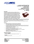
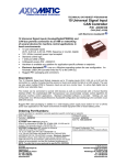
PreView® VideoLink PVL4000 Operating Manual / Installation Guide www.PreViewRadar.com Contents Product Description ...................................................... 1 VideoLink Description ............................................. 2 Features ................................................................. 3 Compatibility ........................................................... 3 Installation Instructions ................................................ 3 Troubleshooting ........................................................... 6 Specifications ............................................................... 7 Warranty Information ................................................... 9 TRADEMARKS The names of actual companies and products mentioned herein may be the trademarks of their respective owners. Any rights not expressly granted herein are reserved. Product Description ® The PreView VideoLink is a device used to integrate a PreView Object Detection sensor with a blind spot camera system. The PreView VideoLink uses the blind spot camera’s monitor to display PreView distance information to the vehicle operator. The VideoLink consolidates the displayed information into a common point of focus for the operator rather than forcing the operator to monitor multiple devices in the vehicle cab. This is achieved by replacing the PreView display with the VideoLink component, where the visual alert and ranging information from the PreView sensor (or sensors) is modulated right onto the existing video monitor, sharing the resulting video image on a single monitor. During times when no object is present, the VideoLink graphic information is static and unobtrusive. Conversely, during times when an object is present, the active alert of the PreView VideoLink draws the operator's attention to the monitor using a combination of a dynamic graphics display as well as audible tones, where the standard PreView system object warning tones are also modulated right onto the existing video monitor, sharing the camera audio sound (if so equipped). The information is positioned for minimal interference with the camera image and the standard five-zone PreView display format is preserved. The VideoLink reduces installation time, installation costs, and dash clutter when installing a PreView Object Detection system on vehicles. The PreView VideoLink consists of three major components: an environmentally sealed housing containing the electronics, a cable that interfaces to the camera and monitor, and an interface cable to the PreView radar sensors. The PreView VideoLink can be used with many different manufacturers of camera systems. All that is required is the proper camera interface cable. (866) 977-7326 www.PreViewRadar.com Page 1 370-002-7F Copyright 2011 VideoLink Description The PreView VideoLink accepts a camera video signal, processes this video signal, and then outputs the signal in the same format to a monitor for display. This processed signal includes the camera image as well as the data used to indicate the range to the closest object as detected by the PreView sensor. The picture below shows a sample image with the PreView sensor data inserted. The PreView data inserted on the video signal consists of both black and white pixels. By using both black and white data, the information will always be visible independent of the background. Because the PreView data is object based and does not include alpha numeric characters, it is not affected by the image being mirrored. The PreView VideoLink will not interfere with normal operation of the camera system. In addition to the video image, the VideoLink also provides an audible tone on the monitor if the camera is equipped with a microphone. This audible tone will increase in rate as the distance to a detected object decreases. The PreView VideoLink is designed to function with all camera/monitor systems that are both NTSC and PAL formats. (866) 977-7326 www.PreViewRadar.com Page 2 370-002-7F Copyright 2011 Features NTSC and PAL video compatible Provides PreView range information on monitor as well as sensor status Provides audible indicator using existing camera microphone and monitor speaker (if equipped) Optional audible indicator with an external buzzer Interfaces with CAN bus version of PreView sensors (High Resolution and Xtreme) Interfaces with serial communication based PreView sensors Compatibility ® The PreView VideoLink is compatible with all NTSC and PAL camera/monitor systems. Preco currently offers a variety of adapter cables for camera/monitor systems. Please contact Preco for available manufacturer options. ® ® The PreView VideoLink is compatible with the High Resolution PreView Sensor ® ® (HRPV4xxx), the Xtreme PreView Sensor (XPV4xxx), the WorkZone PreView ® ® Sensor (WZPV5xxx), the WorkSight PreView (WS6xxx) and the Waste industry ® version of the Standard PreView (SPV2020-2xx). Installation Instructions Before You Start Prior to installing the PreView VideoLink, take time to familiarize yourself with the installation instructions, theory of operation, and system components. At a minimum, the following components are required for a system installation: PreView VideoLink (1) Camera Adapter Cable (not included with VideoLink) Sensor Adapter Cable (not included with VideoLink) Mounting Hardware 1-1/2” x 1/4” – 20 Bolts (2), 1/4” - 20 Nuts (2), 1/4” Washers (2), 1-1/2” x 1/4” – 20 Lag Bolts (2) Mounting Location The PreView VideoLink is required to be installed between the camera and the camera/monitor cable. Depending on the application and cables purchased, the VideoLink will need to be mounted either close to the reversing camera, or in the cab near the monitor. See installation guide for more information. VideoLink Mounting 1. Select the appropriate mounting location. 2. It is best to mount the box with the cable exits pointed down. 3. Use the box’s mounting holes as a template, scribe position marks through the holes. Drill 5/16” (8mm) holes centered at the marks. 4. Secure the box to the vehicle with the two supplied 1/4-20 UNC bolts, washers and nuts or equivalent. Alternately, the supplied lag bolts can be used if the mounting conditions dictate. Apply a maximum torque of 50 inch pounds when securing the box. (866) 977-7326 www.PreViewRadar.com Page 3 370-002-7F Copyright 2011 Connections The PreView VideoLink requires two adapter cables (sold separately). One adapter cable connects between the camera and monitor cable (black connector) and is specific to the camera/monitor manufacturer. The other adapter cable provides power to the device as well as connects to the PreView radar sensor (gray connector). This cable is specific to the sensor type. Both of these cables are waterproof, even though the sensor cable does not have the over mold. If the sensor adapter cable is not long enough for the application, contact Preco customer service for information on extension cables. The diagram below shows the required connections. PreView Sensor Power (Red) Ground (Black) Alarm Out (Blue) Camera PreView VideoLink To Monitor In addition to video and audio inputs and outputs, the PreView VideoLink provides two signal paths that loop through the device to maintain system functionality. One of these signals is for camera power. Depending on the camera system, the other path may be utilized for the camera heater or the image mirror function. These functions are designed into the adapter cables and no user intervention is required. Power Connection Different power connection options allow different uses of the monitor. The video image on the monitor will not be present if power is not applied to the PreView VideoLink. Typically power for a camera system is taken from a source that becomes active when the vehicle ignition is on (keyed). The typical power source for a PreView sensor is from a vehicles reverse circuit. The matrix below shows the different power connections and the resulting functionality. (866) 977-7326 www.PreViewRadar.com Page 4 370-002-7F Copyright 2011 VideoLink Power Keyed (Constant on) Monitor Power Monitor Trigger Keyed None Keyed Keyed Reverse Reverse Keyed None Reverse Keyed Reverse Monitor Image Monitor image on constantly with sensor data Monitor image appears once the vehicle is placed in reverse Monitor image appears once the vehicle is placed in reverse Monitor image appears once the vehicle is placed in reverse The power connection should be done using a 5A fast-blo fuse (not supplied). Either an in-line fuse block or an unused fuse on the vehicles fuse panel can be used. Note that power for the PreView radar sensor(s) is not provided by the PreView VideoLink. Optional Buzzer Connection If desired, an optional buzzer (Model PVL-410B) may be added to the system providing a louder audio function when an object is detected. Contact Preco Electronics for information on this option. Initial System Power Up and Test Once the VideoLink has been installed, the complete video and radar system needs to be tested. The first step is to verify that there is an image on the monitor. If there is no image on the monitor, verify that the monitor and VideoLink have power applied and the camera adapter cable is properly connected. Testing of the radar system is typically accomplished by using two individuals. One individual remains in the vehicle, engages the vehicle brake, and places the vehicle in the appropriate gear. The other individual then walks through the detection zone. The individual in the vehicle then notes where the Video Link activates and communicates this to the person walking through the detection zone. (866) 977-7326 www.PreViewRadar.com Page 5 370-002-7F Copyright 2011 Troubleshooting If there is any problem with the system, the first step is to remove the VideoLink from the system to verify camera/monitor functionality. Simply disconnect the VideoLink from the camera and reconnect the camera to the monitor. No video image on monitor. Verify that DC power (9-33V) is applied to the VideoLink. Verify that DC power is applied to the monitor. Verify that the cables between the VideoLink and camera are connected. Overlay on monitor, but no video image displayed. Indicates that there is a problem with the camera Verify that the cables between the VideoLink and camera are connected. Sensor status shows failed on monitor. There are three possible error designations: Failed Sensor Missing Sensor No Communication Verify that DC power (9-33V) is applied to the PreView radar sensor. Verify that the cables between the VideoLink and sensor are connected. No audio on monitor. Verify that DC power (9-33V) is applied to the VideoLink. Verify that DC power is applied to the monitor. Verify that the cables between the VideoLink and camera are connected. Consult the camera manufacturer’s instruction/user manual for monitor audio and volume settings. (866) 977-7326 www.PreViewRadar.com Page 6 370-002-7F Copyright 2011 Specifications MECHANICAL SPECIFICATIONS Model: PVL4000 Connector: Deutsch DTM13 series Sealing: Encapsulated to protect from dust and moisture to IP67. Housing Material: Nylon Dimensions: 5.24”H x 4.63"W x 1.45"D (13.0cm x 11.8cm x 3.6cm) Weight: 1.0 lb. (0.45 kg) o o o o Operating Temperature: -40 F to +185 F (-40 C to +85 C) Vibration: 25G RMS all three axes Shock: 25G all three axes Mounting: Two 0.29" (7.4mm) diameter holes on 4.00” centers. Recommended torque is 50 inchlbs. ELECTRICAL SPECIFICATIONS Input Voltage: Input current: Polarity: Power Connection: 9-33VDC, over voltage protected to 150V 0.2 amp maximum operating, 1A in rush Negative ground, Polarity protected to 150V Available through sensor connector VIDEO SPECIFICATIONS (TYPICAL) Composite Video Signal Differential Gain Differential Phase Large Signal Bandwidth (0.2dB) Signal to Noise, 15KHz - 5MHz SENSOR COMMUNICATION Physical Layer: Protocol Layer: ALARM and BUZZER OUTPUT Output: 1Vp-p (75 ohm) 0.5% 0.5 degrees 6 MHz -60dBRMS CAN 2.0B, 250 KB/s SAE J1939 Extended/PrecoNET +150V tolerant, Active State: switched to ground, over current protected to 50mA sink maximum. Inactive State: high impedance PRODUCT MANUFACTURED IN THE USA (866) 977-7326 www.PreViewRadar.com Page 7 370-002-7F Copyright 2011 CONNECTOR DESCRIPTIONS SENSOR INTERFACE CONNECTOR Pin 1 – CAN High Pin 2 – Loop Input Pin 3 – UART Input Pin 4 – UART Enable Input Pin 5 – Power Output Pin 6 – Power Input Pin 7 – Ground Input Pin 8 – Ground Output Pin 9 – N/C Pin 10 – Buzzer Output Pin 11 – Loop Output Pin 12 – CAN Low CAMERA INTERFACE CONNECTOR Pin 1 – Video Input (from camera) Pin 2 – Ground Pin 3 – Camera Power Input (loop #1) Pin 4 – Audio Input (from camera) Pin 5 – Ground Pin 6 – Ground Pin 7 – Video Output (to monitor) Pin 8 – Heater or Image Mirror Input (loop #2) Pin 9 – Heater or Image Mirror Output (loop #2) Pin 10 – Camera Power Output (loop #1) Pin 11 – Audio Output (to monitor) Pin 12 – Ground (866) 977-7326 www.PreViewRadar.com Page 8 370-002-7F Copyright 2011 Warranty Information MANUFACTURER LIMITED WARRANTY AND LIMITATION OF LIABILITY Manufacturer warrants that on the Date of Purchase this Product will conform to Manufacturer's published specifications for the product, which are available from Manufacturer on request, and Manufacturer warrants that the product is free from defects in materials and workmanship. This Limited Warranty extends for twenty-four (24) months from the date of shipment. Manufacturer will, at its option, repair or replace any product found by Manufacturer to be defective and subject to this Limited Warranty. This Limited Warranty does not apply to parts or products that are misused; abused; modified; damaged by accident, fire or other hazard; improperly installed or operated; or not maintained in accordance with the maintenance procedures set forth in Manufacturer's Installation and Operating Instructions. To obtain warranty service, you must ship the product(s) to the specified Manufacturer location within thirty (30) days from expiration of the warranty period. To obtain warranty service you must call Preco Customer Service at 866-977-7236 or 208-323-1000, or fax your request to 208-323-1034. Customer Service will issue warranty authorization and further instructions. You must prepay shipping charges and use the original shipping container or equivalent. EXCLUSION OF OTHER WARRANTIES: MANUFACTURER MAKES NO OTHER WARRANTIES, EXPRESSED, IMPLIED OR STATUTORY. THE IMPLIED WARRANTIES FOR MERCHANTABILITY OR FITNESS FOR A PARTICULAR PURPOSE ARE HEREBY EXCLUDED AND SHALL NOT APPLY TO THE PRODUCT. BUYER'S SOLE AND EXCLUSIVE REMEDY IN CONTRACT, TORT OR UNDER ANY OTHER THEORY AGAINST MANUFACTURER RESPECTING THE PRODUCT AND ITS USE SHALL BE THE REPLACEMENT OR REPAIR OF THE PRODUCT AS DESCRIBED ABOVE. LIMITATION OF LIABILITY: IN THE EVENT OF LIABILITY FOR DAMAGES ARISING OUT OF THIS LIMITED WARRANTY OR ANY OTHER CLAIM RELATED TO MANUFACTURER'S PRODUCTS, MANUFACTURER'S LIABILITY FOR DAMAGES SHALL BE LIMITED TO THE AMOUNT PAID FOR THE PRODUCT AT THE TIME OF ORIGINAL PURCHASE. IN NO EVENT SHALL MANUFACTURER BE LIABLE FOR LOST PROFITS, THE COST OF SUBSTITUTE EQUIPMENT OR LABOR, PROPERTY DAMAGE, OR OTHER SPECIAL, CONSEQUENTIAL OR INCIDENTAL DAMAGES BASED UPON ANY CLAIM FOR BREACH OF CONTRACT, NEGLIGENCE OR OTHER CLAIM, EVEN IF MANUFACTURER OR A MANUFACTURER'S REPRESENTATIVE HAS BEEN ADVISED OF THE POSSIBILITY OF SUCH DAMAGES. Manufacturer shall have no further obligation or liability with respect to the product or its sale, operation and use, and Manufacturer neither assumes nor authorizes the assumption of any other obligation or liability in connection with such product. This Limited Warranty gives you specific legal rights, and you may also have other legal rights which vary from state to state. Some states do not allow the exclusion or limitation of incidental or consequential damages, so the above exclusion or limitation may not apply to you. Any oral statements or representations about the product which may have been made by salesmen or Manufacturer representatives do not constitute warranties. This Limited Warranty may not be amended, modified or enlarged, except by a written agreement signed by an authorized official of Manufacturer which expressly refers to this Limited Warranty. (866) 977-7326 www.PreViewRadar.com Page 9 370-002-7F Copyright 2011 Proudly developed by 10335 W. Emerald St. Boise, Idaho 83704 Phone 1.866.977.7326 (866) 977-7326 www.PreViewRadar.com Page 10 370-002-7F Copyright 2011